Spare parts for trucks
Full model range: GAZ-3307, 53, GAZ-3309, GAZ-66, 3308, 33081, 33086, GAZ-33104
Engine cooling system GAZ-53
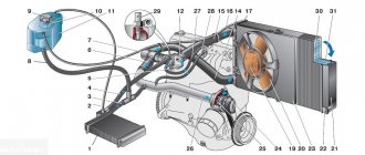
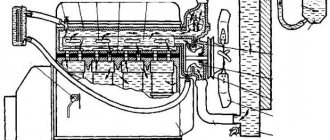
The GAZ-53 engine cooling system (Fig. 1) is liquid, closed, with forced circulation of liquid, filled with low-freezing liquid Antifreeze.
The most favorable temperature regime for engine operation is within 80 - 90 °C. The specified temperature is maintained using thermostat 6, which operates automatically, and blinds controlled by the driver.
Fig.1. Cooling system GAZ-53
1 - radiator; 2 — engine overheat indicator sensor; 3 - water pump; 4 — bypass hose; 5 — radiator supply hose; 6 — thermostat; 7 — coolant temperature indicator sensor; 8 — heater connection fitting; 9 — water jacket of the cylinder block; 10 — radiator outlet hose; 11 — radiator drain valve; 12 - fan; 13 - blinds; 14 — fan casing; 15—radiator plug
To control the coolant temperature, there is a temperature indicator on the instrument panel, sensor 7 (TM100-B) of which is installed in the water jacket of the intake pipe. In addition, there is a warning light on the instrument panel that lights up when the coolant temperature rises to 104–109 °C.
Sensor 2 of the signaling device (TM104-T) is screwed into the upper radiator tank. When the lamp lights up, you should immediately stop the engine, find out and eliminate the cause of its overheating.
Thermostat GAZ-53 with solid filler, single-valve TS 108 (Fig. 2). It is installed in a special cavity at the coolant outlet from the inlet pipe.
Thermostat consists of valve 3, seat 2, thermal power element 5 with rod 1 and spring 4, where L is the valve stroke.
Fig.2. Thermostat GAZ-53
The GAZ-53 thermostat valve begins to open at a temperature of 78-82 °C, and at a temperature of 93-95 °C it is completely open.
Water pump (pump) GAZ-53 of centrifugal type (Fig. 3). Roller 2 of the water pump rotates in two ball bearings and has flats at the ends.
The impeller of the GAZ-53 pump is pressed onto one end of the shaft, and the hub onto the other. The impeller is secured with a bolt screwed into a threaded hole in the end of the shaft. The hub is secured with a nut screwed onto the threaded end of the shaft.
Ball bearings with a spacer sleeve between them are sandwiched between the pulley hub and the thrust ring; They have felt seals at the outer ends, mounted in the outer races of bearings secured in the housing with a locking ring.
Fig.3. Water pump (pump) GAZ-53
The cavity of the GAZ-53 pump, in which the coolant circulates, is separated from the cavity in which the bearings are mounted by a rubber self-moving oil seal with a sealing washer made of a graphite-lead composition.
A spring 8, brass clips 9 and 10, a cuff 11, a sealing washer 12 are installed in the recess of the pump impeller and are locked with a ring 13. The liquid seeping through the oil seal flows out through hole 7 in housing 3.
Through a grease nipple 5, screwed into the body of the GAZ-53 water pump (pump), the bearings are lubricated until the grease appears in the control hole 4. Excess grease should be removed immediately to avoid getting it on the fan and water pump drive belts and pulley streams.
Oily belts and grooves should be wiped with a rag lightly moistened with gasoline. Litol-24 grease is used to lubricate the bearings. It is allowed to use a fatty lubricant as a backup.
Two steel side rack-plates are soldered to the upper and lower tanks of the GAZ-53 radiator, which give the radiator the necessary rigidity and also provide the ability to attach the fan casing to it.
The GAZ-53 radiator is attached in the lower part to special brackets on the frame using rubber gaskets and in the upper part - with two rods.
The radiator cap has two valves: a steam valve, which opens at an excess pressure of 45 - 60 kPa, and an air valve, which opens at a vacuum of 1 - 10 kPa.
The GAZ-53 fan is six-blade, metal, consists of two crosspieces, between which the blades are riveted, and is attached together with a pulley with four bolts to the hub of the pump shaft.
The fan is statically balanced and driven by a V-belt from the crankshaft pulley. The belt is tensioned by turning the generator, which is driven by the same belt.
The correct belt tension is checked by pressing a spring dynamometer on it with a force of 34 - 44 N. In this case, the fan belt should bend by 10 - 15 mm.
The GAZ-53 fan casing is stamped metal and significantly increases the efficiency of the fan.
The blinds are metal, plate, controlled by a wire rod from the driver's seat. The draft handle has several fixed positions for closing the blinds to ensure the required temperature conditions for the engine.
The upper tank of the GAZ-53 radiator must be filled to the filler neck. A decrease in temperature leads to a decrease in the fluid level, and therefore, at low temperatures, its level in the radiator may decrease.
However, even at temperatures below - 30°C, the liquid level in the radiator must be at least 50 mm above the ends of the cooling tubes.
As the engine warms up, the coolant level rises as the coolant temperature rises.
At subzero temperatures, it is permissible to check the fluid level on a warm engine, for which remove the cap from the GAZ-53 radiator and make sure that there is coolant in the upper radiator tank; install the plug in place, paying attention to its installation; the plug must tightly close the radiator neck to ensure the tightness of the cooling system; warm up the engine to a temperature above 90 °C.
Maintenance and repair of the GAZ-66, GAZ-53 engine cooling system
The engine cooling system is liquid, closed with forced circulation.
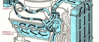
The direction of circulation is shown by arrows in the figure. Depending on the heating, the liquid circulates in two circles, a small and a large circle. With a cold engine, when the thermostat valve is closed, bypassing the radiator, through the bypass hose 6 into the suction cavity of the water pump, and then into the water jacket engine - this is a small circle. When the engine is warm, when the thermostat valve is open, through the outlet pipe 7 along the hose into the upper radiator tank 1, and from the radiator through the supply hose 12 into the engine water jacket - this is a large circle.
Cooling System Maintenance
Check the coolant level every day before leaving. The water level in the radiator should be 40 mm below the upper edge of the filler neck, the level of low-freezing liquid 70-80 mm. Pour clean, soft water into the radiator and change it as often as possible. It is recommended to flush the cooling system in the spring (or better yet, twice a year). Proper engine operation is the most reliable method of combating scale and corrosion in the cooling system. If scale has appeared, then the radiator is washed as follows. The radiator is removed from the car, then a 10% solution of caustic soda (caustic soda), preheated to a temperature of 90˚ C, is poured into it. After 30-40 minutes, the solution is drained and the radiator is washed clean running water in the opposite direction to normal circulation. If necessary, repeat the washing. To avoid destruction of aluminum parts, pouring an alkali solution into the cooling jacket of the cylinder block is unacceptable. Caustic soda solution should be handled with care, as it causes skin burns and corrodes clothing fabrics. Protection of the engine cooling jacket from corrosion can be carried out as follows. Prepare a solution of chrompic at the rate of 4-8 g per 1 liter of water and pour it into the cooling system. Work with this solution for a month (best in the summer), and then drain it. If water boils away from the solution during operation, add water to the system, and if there is a leak, add the solution. You should know that a chromium solution of less than 3 g per 1 l leads to increased corrosion of aluminum parts. Drive belts of units installed on engines must be tensioned so so that they do not slip on the drive pulleys and large loads do not occur on the bearings of the units from over-tensioning the belts. The tension of the drive belt of the water pump and fan on the engine of the GAZ-53A car should be such that under a force of 4 kg applied in the middle of the branch the tension roller - water pump pulley, the deflection does not exceed 10-15 mm, and in the middle of the branch the water pump pulley — generator pulley 10-12 mm. The tension of the water pump belt is adjusted by moving the tension roller, and the generator drive belt is adjusted by moving the generator itself. On a GAZ-66 car engine, the water pump drive belt is also the generator drive belt. Its tension is adjusted by moving the generator. The deflection of the generator-water pump branch under a force of 4 kg should not exceed 10-15 mm. The tension of the compressor drive belts and the power steering pump is adjusted by moving the power steering pump. The deflection of each of the two belts should be no more than 15-20 mm under a force of 1 kg on the compressor pulley -► power steering pump pulley.
When overhauling the radiator, the upper and lower banks must be removed from it. The outer surface of the radiator must be cleaned of dirt, and the inner surface of the tanks and tubes must be free of scale. Dents on the walls of the tanks must be straightened. Radiator tubes must be checked with a special rod made to fit the size and profile of the tubes. Plugged and dented tubes must be replaced with new ones. It is allowed to plug no more than 10 tubes and replace no more than 50 tubes. After repair, the pipes must be blown out with compressed air.
The cooling fins must be straightened. The assembled radiator must be thoroughly washed with an alkaline solution to neutralize zinc chloride and water to remove alkali. The repaired radiator must be tested for leaks with compressed air under a pressure of 1 kg/cm2. A radiator filled with compressed air and immersed in water should not leak air. The radiator cap must be sealed. The outlet valve of the plug must open under air pressure of at least 0.45-0.55 kg/cm2. The inlet valve should open at a vacuum of 0.01 -0.10 kg/cm2. Bent radiator shutter blades must be straightened or replaced with new ones. Repaired blinds should open and close freely when the lever is turned within 90°. When closing the blinds, the gaps between the surfaces of the plates should not exceed 1.5 mm over a length of 200 mm.
water pump . The pump is sealed using a self-tightening seal with a spring. The rubber seal seal and the graphite-lead washer rotate together with roller 2 (Fig. 2).
Liquid leakage through inspection hole 7 indicates a malfunction of the oil seal. In this case, the pump should be repaired. To change the oil seal parts, the pump impeller must be removed by first unscrewing the bolt. It is not allowed to plug inspection hole 7, since in this case the liquid leaking from the pump gets into the bearings and damages them. The bearings are lubricated through grease nipple 5 until fresh grease appears from inspection hole 4. Excess grease must be removed. Before assembling the water pump, all parts must be wiped and blown with compressed air.
When installing the impeller and oil seal of the water pump into the housing, the end surfaces of the textolite sealing washer must be coated with a thin layer of graphite colloidal lubricant. The bearings must be lubricated with refractory grease CIATIM-201.
Fill the bearings with grease until it appears in the control hole of the housing. When installing, fill the hub cover with CIATIM-203 lubricant.
When the water pump shaft rotates, the impeller should not touch the housing; the water pump oil seal must be sealed.
Check the water pump for leaks on a special stand at 3250 rpm and a water temperature of at least 40°C.
Tensioner roller GAZ-53
Before assembly, all parts of the tension roller must be washed and wiped. When assembling, compress the retaining ring on the tension roller axis in the annular groove of the axis to a size of 21.5 mm along the outer diameter of the ring, no more. Place 4-5 g of CIATIM-201 lubricant into the bearing cavity.
Electrical diagram of GAZ 53
The GAZ 53 truck was designed and produced in the Soviet Union, and the automotive equipment in the country at that time was not distinguished by its complexity and the presence of additional options. At that time there were no air conditioners or electric windows, although some cars could have a pre-heater installed. But in the national economy this was more a vital necessity than an element of tuning.
GAZ 53 truck with extended sides
But repairing a GAZ-53 should not be difficult, because the time and labor that you will spend on it will not take much effort from you. Everything can be complicated by the fact that in order to repair various elements, parts, equipment, and so on, when you tinker with the car yourself, you need to have a diagram of these elements. Only they are not there, and the instruction manual has long been lost, because the GAZ-53 has not been produced for 20 years.
Site about off-road vehicles, SUVs, off-road vehicles
The coolant temperature gauge 14.3807 is electromagnetic, ratiometric type. Designed to monitor the temperature of the coolant in the engine. Equipped with an overheat alarm. On UAZ cars it is part of the instrument panel 14.3805 or KP116-3805010. Works in conjunction with the TM100 temperature sensor.
Coolant temperature gauge 14.3807, characteristics.
The coolant temperature gauge 14.3807 is an electromagnetic ratiometer with fixed coils and a moving permanent magnet connected to a pointer. In addition to vehicles of the UAZ-31512 family, UAZ-3741 and UAZ-3909 vans, UAZ-3962 ambulances, UAZ-2206 buses, UAZ-3303 and UAZ-39091 trucks, the coolant temperature indicator 14.3807 is used on GAZ, ZIL, URAL, LUAZ vehicles , and buses PAZ, ERAZ, KAVZ.
Main characteristics of the pointer 14.3807:
— Indication range, degrees Celsius: 40-120 — Graduation value, degrees Celsius: 20 — Type of measuring mechanism: magnetoelectric — Rated voltage, V: 12 — Mounting diameter of the casing, mm: 60 — Mounting diameter for the backlight lamp holder and signaling device, mm: 11.5 — Electrical connection design: 6.35 mm plug — Weight, kg: 0.18
Coolant temperature sensor TM100, characteristics.
Pointer 14.3807 receives readings from the TM100 temperature sensor, which is installed in the engine cylinder head. The working element of the sensor is a thermistor placed in a metal case.
Main characteristics of the TM100 temperature sensor:
— Temperature measurement limits, degrees: 40-120 — Rated voltage, V: 12, 24 — Load current, A: 0.1 — Connection: M3 screw — Wrench size: S19 — Thread: K3/8 — Weight, g: 45
Connection diagram for temperature indicator 14.3807 and temperature sensor TM100.
Warning lamp for the maximum temperature of the coolant in the radiator and temperature sensors TM104 or TM111-09.
The warning lamp is located on the UAZ instrument panel and works in conjunction with the temperature sensor TM104 or TM111-09, which is located in the upper part of the radiator. The bimetallic plate inside the sensor closes the contacts and the warning lamp lights up when the coolant temperature in the radiator is between 91-98 degrees.
During operation of the vehicle, a significant decrease in the level of coolant in the engine cooling system and, as a result, exposure of the tubes in the upper radiator tank is not allowed, since overheating may cause the temperature sensor to fail.
Reversing the TM100 sensor of the coolant temperature indicator and the TM104 or TM111-09 sensor of the warning lamp for emergency overheating of the coolant is not allowed, since the indicator and lamp will not work in this case.
Diagram of connection and operation of the emergency temperature sensor TM104 or TM111-09.
Location of temperature sensors TM100 and TM104 in vehicles of the UAZ-31512 family.
Location of temperature sensors TM100 and TM111-09 in vehicles of the UAZ-3741 family.
Checking the serviceability of temperature indicator 14.3807 and temperature sensor TM100.
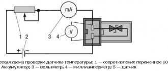
The coolant temperature gauge 14.3807 is checked by comparing its readings with those of a thermometer. To do this, you need to unscrew the TM100 temperature sensor, lengthen its wire if necessary, connect the sensor with a separate wire to the ground of the car and place it together with the thermometer in the middle of a vessel with water heated to a boil. The sensor terminal should not be immersed in water.
Schemes of liquid cooling systems
⇐ PreviousPage 10 of 15Next ⇒The liquid cooling system of automobile engines has become widespread, despite the following disadvantages: freezing of water at low temperatures, which can damage the engine; formation of scale on the internal walls of the system, which reduces heat transfer and causes engine overheating; increased weight and size of the engine due to the presence of double walls.
Car engines GAZ-53A, GAZ-53-12, ZIL-130, MAZ-5335,
KamAZ-5320 and many others have a closed liquid cooling system with forced circulation of liquid created by a centrifugal pump.
Let's consider the operation of the engine cooling system of ZIL-130, MAZ-5335 and KamAZ-5320 vehicles. The water jacket of the ZIL-130 car engine (Fig. 46) is connected to the radiator 1
flexible hoses.
The upper tank 5
of the radiator is connected to the jacket of the inlet pipe 14
, and
the lower tank 27
is
connected to the inlet pipe 26
of the water
The left and right rows of cylinders are connected to the pump by two pipelines. in pipe 12,
through which heated coolant is supplied to the upper radiator tank. Compressor water jacket with flexible hoses
Rice. 46.
Car engine cooling system
ZIL-130:
/ — radiator; 2 —
blinds;
3 -
fan;
4 - water pump; 5 and 27 -
upper and lower radiator tanks, respectively;
b
— radiator cap; 7 — outlet hose; # — compressor;
9 —
supply hose;
10 —
bypass hose;
11
— thermostat;
12
- pipe;
13
- flange for
carburetor installation; 14
— inlet pipeline;
15
— heater valve;
16
and
17
- inlet and outlet tubes, respectively;
18
— heater radiator;
19
— liquid temperature indicator sensor;
20
— dosing insert;
21 —
water jacket of the block head;
22 —
water jacket of the cylinder block;
23
— drain valve of the cylinder block jacket;
24 —
drain valve drive handle;
25
— drain valve of the radiator pipe;
26
— supply pipe
9 and 7 are constantly connected to the engine cooling system. Radiator 18
the heater is connected to the engine cooling system by pipes
16
and
17;
The heater is switched on by tap 75.
When starting, warming up and operating the engine, while the water temperature in the cooling system is below 73 C, the liquid circulates through the water jackets of the block, block heads and compressor, but does not enter the radiator, since the thermostat is closed. Coolant is supplied to the water pump (regardless of the position of the thermostat valve) through a bypass hose 10
from the intake manifold jacket, the compressor and from the heater radiator
18
(if it is turned on).
The water pump forces fluid into the system, and its main flow passes through the water jacket of the cylinder block from its front to the rear. By washing the cylinder liners from all sides and passing through the holes in the welding surfaces of the cylinder block and cylinder heads, as well as in the gasket located between them, the coolant enters the cylinder head jackets. In this case, a significant amount of coolant is supplied to the most heated parts and areas - exhaust valve pipes and spark plug sockets. In block heads, coolant moves longitudinally from the rear end of the block to the front due to the presence of holes drilled in the welding surfaces of the cylinder block and heads, and metering inserts 20,
installed in the rear intake manifolds. The hole in the insert limits the amount of fluid entering the intake manifold jacket. The heated liquid passing through the jacket of the intake pipeline heats the combustible mixture coming from the carburetor (through the internal channels of the pipeline), as a result of which mixture formation is improved.
Before starting work, it is necessary to check the fluid level in the radiator, since if there is insufficient amount of fluid, the fluid circulation is disrupted and the engine overheats. The quality of water used to cool the engine is no less important for the durability and reliability of its operation than the quality of fuel and lubricants. The use of clean and soft water is one of the main conditions for technically correct operation of the engine. The cooling system should be filled with clean, soft water that does not contain lime salts. When using hard water, a large amount of scale is deposited in the radiator and water jacket, which leads to overheating of the engine and a decrease in its power. Frequent changes of water in the cooling system also cause increased scale formation. You can soften water in the following ways: boiling, adding chemicals to water, and treating it magnetically. It has been established that, passing through a weak magnetic force field, water acquires new properties: it loses its ability to form scale and dissolves previously formed scale that was in the engine cooling system.
Water is poured into the cooling system through the radiator neck, which is closed with a plug. 6
(Fig. 46).
To drain the water, taps located at the lowest points of the cooling system are used. The cooling system of the YaMZ-236 diesel engine is shown in Fig. 47. A feature of the system is the location of pump 1
and its drive, which is not combined with a fan, like most engines.
In addition, each cylinder head has a water collection pipeline with a separate thermostat 5. The thermostat boxes of the left and right pipelines are connected to each other by pipe 6.
If the engine is not warmed up, the liquid is pumped from the lower radiator tank through the channels in the cover of the timing gear block. From there it enters the water jackets of the right and left rows of cylinders, washes the cylinder liners and enters the block heads to the hottest places - exhaust valves and injector cups. Next, the liquid from the cylinder heads through two channels enters the drainage pipelines 4
with thermostats 5. Since they are closed, the coolant through the connecting
6
and bypass 7 pipes returns to the pump (small circulation circle).
Rice. 47.
Diesel cooling system YaMZ-236:
/ - liquid pump; 2
— connection point for the pre-heater;
3 — coolant temperature indicator sensor; 4
- drainage pipeline;
5 —
thermostat;
7— connecting pipe; 7 - bypass pipe
heated places - exhaust valves and nozzle cups. Next, the liquid from the cylinder heads enters the drainage pipelines through two channels. 4
with thermostats 5. Since they are closed, the coolant through the connecting
6
and bypass 7 pipes returns to the pump (small circulation circle).
When the fluid temperature increases above 70 °C, the thermostat valves open (their full opening occurs at a fluid temperature of 85 °C), and the coolant enters the radiator in two streams.
In the cold season, it is better to fill the cooling system with low-freezing liquid (antifreeze). It has a freezing point of -40 or -65С (GOST 159-52*) and is a mixture of ethylene glycol, water and various additives. To protect metal from corrosion caused by ethylene glycol, a special additive is added to liquids that freeze at low temperatures. These liquids are poisonous, so contact
Figure 48.
Cooling system of the KamAZ-740 diesel engine: / - crankshaft pulley; 2 —
lower tank;
3
- blinds;
4
- radiator;
5
— fluid coupling of the fan drive;
6 —
bypass pipe;
7 - discharge pipe; 8
— upper tank;
9 —
upper pipe;
10
— thermostat;
11—
water distribution box;
12
- connecting rough;
13 —
supply tube;
14
— right water pipe;
15 —
outlet tube;
16
— intake manifold;
/7 — liquid overheating control lamp sensor; 18
— expansion tank;
19—
neck with a sealing plug;
20
— plug with valves;
21
— outlet pipe from the compressor;
22 —
outlet tube of the left water pipe;
23 -
compressor;
24 ~
left water pipe;
2.5 — head cover; 26 —
cylinder head;
27
- water pump;
28
— drain valve (plug);
29
— water pump pulley;
30 -
fan;
31 -
lower pipe
with top tank 8
radiator, water distribution box, compressor 23
and
water jacket of the cylinder block.
The expansion tank compensates for changes in the volume of liquid when it is heated and allows you to control its level in the cooling system. Steam from the upper sections of the radiator and system is removed and condensed into the tank, and air is also collected, as a result of which the operation of the cooling system improves. Liquid is poured into the cooling system through neck 19,
which has a sealing plug on the thread.
The steam and air valves are installed in plug 20.
The diesel cooling system uses a hydraulic coupling (Fig. 49) for the fan drive, which has automatic control and transmits torque from the engine crankshaft to the fan. The fluid coupling allows you to maintain the most favorable temperature conditions in the cooling system and dampen the resulting vibrations of the crankshaft during a sharp change in its rotation speed.
The fluid coupling is driven from the engine crankshaft through a splined drive shaft 6.
The fan, located in alignment with the crankshaft, is mounted on a hub
15
mounted on the driven shaft
16.
The driving part of the fluid coupling consists of: drive shaft
6
assembled with casing
3;
drive wheel 10
, bolted
pulley // driving the pump and generator, attached to the shaft with bolts
19.
The driving part of the fluid coupling rotates on ball bearings 7 and
20.
The driven part of the fluid coupling consists of: driven wheel
9
assembled, connected by bolts
22
to the driven shaft
16.
The driven part of the fluid coupling of the fan drive rotates on ball bearings
4
and
13.
Fluid coupling seal
Rice. 49.
Fluid coupling of the KamAZ-740 diesel fan drive:
a - design; b —
fluid coupling switch with thermal power sensor: / - front cover:
2 -
housing;
3 -
casing;
4,
7,
12, 13 and 20 -
ball bearings;
5 —
oil supply tube;
b -
drive shaft;
8
- sealing ring;
<> — driven wheel; 10 —
drive wheel;
// - pulley; 14 -
thrust bushing;
15 —
fan hub;
16
— driven shaft;
17
and
21
- self-clamping oil seals;
18
— gasket;
19
and
22 -
bolts;
23
— switch housing;
24
- valve plug lever: 25 - thermal power sensor
carried out by two o-rings 8
and self-clamping seals
17
and
21.
There is a switch to control the hydraulic coupling of the fan drive (Fig. 49, b)
spool type, installed on the discharge pipe 7 (see Fig. 48) in the front part of the engine.
Depending on the temperature of the fluid in the cooling system, the fluid coupling switch connects or disconnects the drive shaft from the driven shaft, changing the amount of oil entering the fluid coupling from the lubrication system. Oil for the operation of the fluid coupling is supplied to its cavity by a pump, then through tube 5 (Fig. 49) it is supplied to the channels of the drive shaft and through the holes in the driven wheel into the inter-blade space. When the drive wheel 10
, oil from its blades flows onto the blades of the driven wheel 9, which begins to rotate, transmitting torque to the shaft
16
and the fan.
Using lever 24
of the valve plug (Fig.
49.6),
the fluid coupling is turned on or off, and in connection with this the fan is turned on or off.
The valve is located in housing 23
of the fluid coupling switch.
The fan can operate in three modes:
automatic
— the temperature of the coolant in the engine is maintained at 80 - 95 ° C;
lever 24
of the fluid coupling switch valve plug is set to position
B
(mark on the body), and oil from the lubrication system enters the fluid coupling; when the coolant temperature decreases below 80 C, the fan automatically turns off;
fan is off
— the valve lever of the fluid coupling switch is set to position
0,
and oil does not flow into the fluid coupling; the fan can rotate at a low frequency under the influence of the incoming air flow when the car is moving;
the fan is constantly on -
the switch tap lever is set to position I; oil enters the fluid coupling regardless of temperature conditions, and the fan constantly rotates at a frequency approximately equal to the crankshaft speed. In this mode, short-term operation is allowed in case of possible malfunctions of the fluid coupling or its switch. The problem must be corrected as soon as possible. The main operating mode of the fluid coupling is automatic. The temperature of the liquid in the cooling system is controlled by a remote thermometer, the receiver of which is located in the driver's cabin on the instrument panel, and the sensor is either in the water distribution box (KAMAZ-5320 car engine) or in the water channel of the intake pipeline (GAZ-5320 car engines). 53A, GAZ-53-12 and ZIL-130), or in the block head (engine of the GAZ-24 Volga car). If the temperature of the water in the cooling system exceeds a certain value (for example, 104-109 C), then a warning light, for example red, lights up on the instrument panel (cars
GAZ-53A and GAZ-53-12).
§ 25. Liquid cooling system devices
Radiator. The heat exchanger, in which heat from the liquid is transferred through tubes to the air, is a radiator with an upper 9 (Fig. 50) and lower 75 tanks connected by a core 12
radiator
A filler neck 8,
closed with a plug 7, and a pipe for connecting a flexible hose supplying heated liquid to the radiator are soldered into the upper tank.
On the side of the filler neck there is a hole for a steam pipe. The outlet flexible hose 13
. Side posts 6 are attached to the upper and lower tanks, connected by a plate soldered to the lower tank. The struts and plate form the frame of the radiator.
Car radiator cores can be tubular-plate or tubular-band. The core of a tubular-plate radiator consists of several rows of tubes soldered into the upper and lower tanks. The tubes are covered with thin cooling plates made of brass, aluminum or copper. Sometimes the cooling plates are made corrugated, which significantly increases the cooling surface area of the radiator. A wide corrugated tape is placed between the tubes and soldered to them. The engines of GAZ-24 Volga cars have this design of tubular-band radiators. ZIL-130, GAZ-53A, KamAZ-5320, GAZ-53-12, GAZ-3102 “Volga”, etc.
The radiator is connected to the engine cooling jacket by pipes and flexible hoses, which are attached to the pipes with clamps. This connection allows for relative movement of the engine and radiator. There are blinds in front of the radiator 2
to regulate the amount of air passing between the radiator tubes.
When you move the handle 4
installed in the bracket forward until it stops, the blinds open completely and air passes freely between
radiator tubes. If this handle is moved back all the way, the flaps close and the air flow to the radiator stops. To maintain a certain engine temperature, the handle can be mounted on a lock 5
in any intermediate position.
Neck 8
(Fig. 50, (5) is hermetically sealed by a plug that isolates the engine cooling system from the environment. The radiator plug consists of a housing
18,
a steam valve
22
and an air valve 25
and
21.
On a stand 20
, with
, a steam valve is installed, pressed by a spring
19.
The air valve
25
is pressed by a spring
26
to the seat
27,
pressed into the steam valve. Tight connection of the valves with the seats is achieved by installing rubber gaskets
23
and
24.
If the rubber gaskets are damaged or destroyed, the cooling system becomes open and water boils at 100 °C.
Fig.50.
Radiator:
a - details; O -
the steam (outlet) valve is open:
c -
the air (intake) valve is open;
/ - frame; 2 -
blinds;
3 -
traction;
4
— blinds drive handle;
5 —
clamp;
6 -
stand;
7 — radiator cap; 8 —
radiator neck;
9
— upper tank;
10
and
13
- flexible hoses;
11
— outlet pipe;
12
— radiator core;
14
— radiator drain valve;
15
- lower tank;
16
— guide casing:
17
— steam pipe;
/^ - plug body; 19 —
steam valve spring;
20 -
stand;
21
— locking spring;
22
— steam (exhaust) valve
U23
— exhaust valve gasket;
24 —
air valve gasket;
25
- air valve;
26
— air valve spring;
27
— air valve seat;
28
- hole for air intake
If the liquid boils in the cooling system, the vapor pressure in the radiator increases. When the pressure increases to 145-160 kPa, the steam valve opens 22,
overcoming the resistance of spring
19.
The engine cooling system communicates with the environment, and steam leaves the radiator through the steam pipe
17.
After stopping the engine, the liquid is cooled, the steam condenses, and a vacuum is created in the cooling system.
When the pressure drops to 1 - 13 kPa, the air valve 25 opens , and
into the radiator through holes 28
and
the valve, passing through the steam pipe. Steam and air valves prevent possible damage to the radiator under the influence of both external and internal pressure.
Water pump. A centrifugal pump is used to create forced circulation of liquid in the cooling system. On cars GAZ-53A, GAZ-53-12, GAZ-24 Volga, ZIL-130, water pumps are structurally combined with fans and have a common drive. The water pump (Fig. 51) of the GAZ-53-12 car engine is mounted on the front end of the cylinder block. Building 3
The pump consists of two parts: one part is cast from cast iron and attached to the other, made together with the cover of the timing gear block made of aluminum alloy.
Shaft 2
and fan hub
1
rotate on two ball bearings
14,
pressed into housing
3.
The ball bearings are kept from displacement by a spacer sleeve and retaining rings.
To retain lubricant and protect against contamination, ball bearings have seals. At one end of the shaft there is a pressed hub for the fan and the pump and generator drive pulley. The hub is held against axial displacement by a washer and a castle nut, which is carefully secured with a cotter pin. At the other end of the shaft there is a pressed plastic impeller 6,
which has a steel hub.
The impeller is kept from moving by a washer and a bolt screwed into the end of the shaft. Shaft 2
in the housing is sealed with a self-clamping oil seal, consisting of a graphitized textolite washer
12,
a rubber cuff 77 and two clips
9
and 10 and a spring
8.
The oil seal rotates together with the impeller and pump shaft.
Spring 8,
through a rubber cuff, presses washer
12
to the ground plane of housing
3,
which prevents liquid from flowing out of the pump. Water leaking through inspection hole 7 indicates a malfunction of the self-clamping oil seal. In this case, the pump must be removed from the engine and repaired. Pump ball bearings are lubricated
Rice. 51.
Water pump of the GAZ-53-12 car engine: / - fan and pulley hub; 2 —
shaft;
3
- body;
4
- control hole for the exit of lubricant from the housing;
5—oiler; 6
— impeller;
7 - control hole for water outlet in case of oil seal leak; 8—spring; 9
and
10 —
oil seal races;
11
— oil seal cuff;
12
— oil seal washer;
13 —
seal locking ring;
14 -
ball bearings
a plastic lubricant that is not washed out by water. Through lubricant 5, lubricant is supplied by a syringe into the pump housing until fresh material emerges from the control hole 4.
Excess lubricant must be removed, as it destroys the fan belt.
The water pump and fan are driven from the crankshaft pulley using a V-belt drive consisting of a single belt. The belt covers the water pump and fan pulley, the idler pulley and the crankshaft pulley. The fan pulley is double-groove. The second belt from the fan pulley is transferred to the generator pulley. For normal operation of belt drives, the belt tension should not be very weak and not very tight. The tension of the water pump belt is adjusted by moving the tension roller, and the generator drive belt is adjusted by moving the generator. With the correct tension of the first belt, the deflection under the influence of a force of 40 N (4 kgf) applied in the middle of the tension roller - water pump pulley branch should be 10-15 mm, and in the middle of the second branch, the water pump pulley - generator pulley is 10-12 mm.
Water pumps for YaM 3-236 and KamAZ-740 diesel engines are working! just like engine pumps for ZIL-130, GAZ-53A, etc. cars, but they have some features. The YaMZ-236 diesel pump is installed on the right side of the cover of the timing gear block, driven by a V-belt drive and not connected to the fan drive.
The KamAZ-740 diesel water pump is mounted on the front part of the cylinder block on the left side and is driven by a V-belt drive from the crankshaft pulley. The fan is installed separately on a fluid coupling.
Thermostat. The thermostat automatically maintains the required fluid temperature in the cooling system. It allows you to quickly warm up a cold engine when starting. Thermostats with liquid and solid fillers are used on automobile engines. Liquid thermostats are filled with an easily evaporating liquid (a mixture of 70% lilac alcohol and 30% water). Ceresin with copper shavings, which has a high coefficient of volumetric expansion, is used as a solid filler.
The liquid thermostat (Fig. 52, a) consists of a housing 7 with windows, a corrugated cylinder 2
and valve
5.
The lower part of the corrugated cylinder is rigidly connected to the bracket
8
of the housing.
3
is soldered to the top of the cylinder . The rod can move in the housing guide. Sometimes a small hole or blowout is made on the thermostat valve on the edge to allow air to escape when liquid is added to the cooling system. The sealed corrugated cylinder contains liquid, occupying approximately half of the internal volume of the cylinder. The air from the cylinder is evacuated, and under normal conditions the cylinder is compressed and the valve is closed.
The liquid thermostat works as follows. If the temperature of the liquid in the cooling system does not exceed 73 C, then the cylinder is compressed and the valve is closed. The liquid flows through the bypass channel to the pump, bypassing the radiator. As the engine warms up, the liquid in the cooling system heats up. When the temperature increases above 73 - 83 C, the liquid in the cylinder begins to evaporate, the pressure in the cylinder increases and the valve opens. Coolant flows into the radiator. At a temperature of 88 -94 C, the thermostat valve is fully open.
Thermostat with solid filler (Fig. 52,6)
located between the inlet pipe
16
and the outlet pipe 6.
against
the body 7 by a spring 13.
It
The latter
, which
The internal space of the cylinder is filled with solid filler
10.
Until the engine is warmed up, the filler (ceresin) is in a solid state and the thermostat valve is closed. When the temperature of the liquid in the cooling system increases to 70 °C or more, the volume of the filler increases, since ceresin
Rice. 52.
Thermostat operating diagrams:
A
liquid (diesel YaMZ-236);
o -
with solid filler (ZIL-130 car engine);
/ — water pump housing; 2 —
corrugated cylinder;
3 -
rod;
4 -
gasket;
5 — thermostat valve; 6 —
pipe for discharging hot liquid;
7 — thermostat housing; 8—
bracket;
9 —
thermostat bottle;
10 -
solid filler;
// rubber membrane: 12
guide sleeve;
13 —
returning spring:
14
— valve rocker arm;
15 -
buffer;
16 —
inlet pipeline;
/ and IV
- thermostats are open; // and closing the thermostats.
Fan. To create an air flow that cools the liquid flowing through the radiator tubes, a fan consisting of an impeller and a hub with a pulley is used. Sometimes a guide casing (diffuser) is attached to the radiator frame for more intensive cooling of the liquid in it, inside which the fan blades rotate (engines of GAZ-53A, GAZ-53-12, ZIL-130, KamAZ-5320, etc.). Fan blades are stamped from sheet steel or made of plastic (engine of the GAZ-24 Volga car). The ZIL-130 car engine fan has blades with ends bent forward. When such a fan rotates, the air supply increases and the radiator is cooled better.
In the YaMZ-236 diesel engine, the fan is driven through a system of gear wheels and receives rotation directly from the gear wheel / (Fig. 53) of the camshaft. Fan drive parts are mounted in the housing 14,
which is bolted to the cover of the timing gear block.
Wheel 2 rotates shaft 5, installed in the fan housing on ball bearings 3.
Self-clamping
pressed
At the front end of shaft 5 there is a generator and compressor drive pulley 13
, a fan impeller hub 9
12
and a rubber elastic coupling //. The clutch transmits rotation to the fan. The elastic coupling absorbs inertial forces that arise when the crankshaft rotation speed changes significantly and relieves the fan shaft from additional torsional forces.
To maintain optimal engine temperature conditions, the cooling system uses shutters, a fan and a thermostat. In cold weather, you should never remove the thermostat, as this can lead to intense engine wear, increased fuel consumption, oil aging, reduced power and other undesirable phenomena. Thus, the constancy of the thermal regime is the most important factor in the economical and reliable operation of the engine.
Rice. 53. YaMZ-236 diesel fan drive:
/ timing gear is small: 2
— gear wheel of the valve;
3—ball bearings; 4
- self-clamping oil seal: 5 - fan shaft;
6 -
bolt;
7- spacer sleeve; 8
— coupling hub;
9
fan impeller hub;
10 -
nut;
// - rubber elastic coupling; 12
fan impeller;
13
— generator and compressor drive pulley;
14 —
fan housing;
15
- high pressure fuel pump drive gear
⇐ Previous10Next ⇒
WHAT IS CONFIDENT BEHAVIOR IN INTERPERSONAL RELATIONSHIPS? Historically, there are three main patterns of differences that exist between...
WHAT HAPPENS WHEN WE FIGHT Without understanding the differences that exist between men and women, it is very easy to lead to a quarrel...
WHAT HAPPENS IN ADULT LIFE? If you are still connected to your mother in the wrong way, you are avoiding separation and independent adult existence...
What Causes Trends in Stock and Commodity Markets Freight Train Theory Explained My first 17 years of market research consisted of trying to figure out when...
Didn't find what you were looking for? Use Google search on the site:
