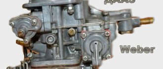
Carburetor DAAZ 2107
The “seven” carburetor, like any other, mixes air and gasoline and delivers the finished mixture to the engine cylinders. To understand the structure and operation of the carburetor, as well as to identify and eliminate possible malfunctions with it, you need to familiarize yourself with this unit in more detail.
Who produces and on what VAZ models it is installed
The DAAZ 2107 carburetor was manufactured at the Dimitrovgrad Automotive Component Plant and installed on different Zhiguli models, depending on the product modification:
- 2107–1107010–20 were equipped with engines of the latest versions of the VAZ 2103 and VAZ 2106 with a vacuum corrector;
- 2107–1107010 was installed on “fives” and “sevens” with engines 2103 (2106);
- carburetors 2107–1107010–10 were installed on engines 2103 (2106) with a distributor without a vacuum corrector.
Carburetor design
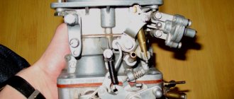
DAAZ 2107 is made of a metal body, which is characterized by increased strength, which allows to minimize deformation and temperature effects, and mechanical damage. Conventionally, the body can be divided into three parts:
- the top one is made in the form of a cover with fittings for hoses;
- middle - the main one, which contains two chambers with diffusers, as well as a float chamber;
- lower - it contains throttle valves (DZ).
The main elements of any carburetor include jets, which are designed to pass fuel and air. They are a part with an external thread and an internal hole of a certain diameter. When the holes become clogged, their throughput is reduced, and the proportions in the process of forming the working mixture are disrupted. In such a situation, cleaning the jets is necessary.
The jets are not subject to wear, so their service life is unlimited.
The “seven” carburetor has several systems:
- float chamber - maintains fuel at a certain level for stable engine operation at any speed;
- main dosing system (GDS) - operates in all engine operating modes, except idle (idle), supplying a balanced gasoline-air mixture through emulsion chambers;
- XX system - is responsible for engine operation when there is no load;
- starting system - ensures a confident start of the power plant when cold;
- econostat, accelerator and secondary chamber: the accelerator pump contributes to the instantaneous supply of fuel during acceleration, since the gas station is unable to provide the required amount of gasoline, and the second chamber and econostat come into operation when the engine develops maximum power.
The principle of operation of the carburetor
The operation of the device can be described as follows:
- Fuel from the gas tank is pumped by a gas pump into the float chamber through a filter and valve, which determines its filling level.
- From the float tank, gasoline is supplied through nozzles into the carburetor chambers. Then the fuel passes into the emulsion cavities and tubes, where a working mixture is formed, which is supplied to the diffusers through atomizers.
- After starting the engine, the electromagnetic valve closes the XX channel.
- During operation at XX, fuel is taken from the first chamber and passes through a nozzle connected to the valve. When gasoline flows through the XX nozzle and part of the transition system of the primary chamber, a flammable mixture is created, which enters the corresponding channel.
- At the moment the throttle body is opened slightly, the mixture is injected into the carburetor chambers through the transition system.
- The mixture from the float tank passes through the econostat and enters the sprayer. When the motor operates at maximum frequency, the accelerator begins to function.
- The accelerator valve opens when filled with fuel and closes when the mixture supply is stopped.
Video: design and operation of the carburetor
Cleaning, troubleshooting, checking the VAZ 2107 carburetor
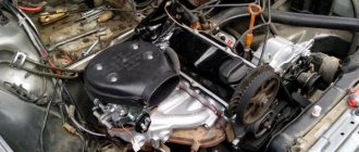
For full service, the unit must be removed from the car. This is done by dismantling the air filter housing, disconnecting the pipes, tubes, cables and solenoid valve wires from the assembly. Afterwards all that remains is to unscrew the 4 nuts securing the carburetor to the intake manifold and remove the assembly.
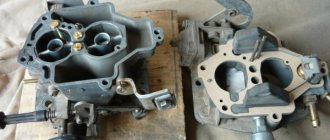
The Ozone carburetor includes three parts. It is better to work with each of them one by one: remove one - disassemble, clean, reassemble and move on to the next component.
Carburetor cover
Let's start with the lid. Maintenance includes the following steps:
- Unscrew the screws securing the cover.
- Disconnect the telescopic air damper control drive.
- Remove the cover from the housing along with the trigger and float.
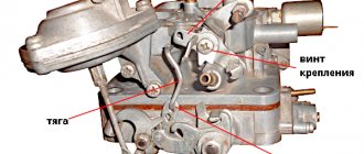
- Unscrew the screws securing the starting device and disconnect the rod from the damper axis lever.
- We remove the float axis and remove the float along with the locking needle.
- We unscrew the filter plug installed on the fuel supply fitting (if the plug does not unscrew, apply a few gentle blows to it with a wrench). Remove the filter element (mesh).
- We remove the gasket.
- We wash the lid from dirt. We blow out the channels in it using a cleaning agent (if you don’t have the product on hand, you can blow it with compressed air).
- We wash and blow through the filter mesh. We put it in place and tighten the plug.
- We examine the condition of the locking needle (the rubber cuff on it). We install the float with the needle in place.
- Check the position of the float (affects the level in the float chamber). This is done like this: we turn the lid over vertically (so that the locking needle closes the feed channel) and measure the distance from the float in the surface of the lid. The distance is 6.5 mm, with this indicator the level corresponds to the norm. If it doesn’t fit, we adjust and adjust the position of the float by bending the tongue.
- Check the tightness of the locking needle. To do this, turn the cap over with the float up and create a vacuum in the inlet fitting with your mouth (extract air from the fitting). If the locking needle “does not hold,” replace it.
- Using vacuum, we check the integrity of the diaphragm of the starting device (when creating vacuum, the rod of the device must move). If necessary, we repair the starting device using a new membrane from the repair kit.
- We install the starting device on the carburetor cover (replacing the sealing collar of the device), connect the rods and the telescopic drive.
Afterwards we put in a new gasket and put the cover aside.
Something else useful for you:
Video: Carburetor Ozone 2107-1107010
Frame
The next stage is cleaning and troubleshooting the case:
- We dismantle the vacuum drive of the second chamber damper.
- We disconnect the throttle body by unscrewing the mounting screws (from the bottom).
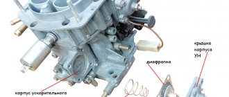
- Disconnect the accelerator pump along with the diaphragm.
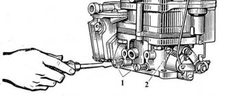
- We unscrew the air and fuel jets (remember or mark where each one was located), remove the emulsion tubes installed under the air jets.
- Unscrew the accelerator pump nozzle.
- Unscrew the accelerator bypass jet.
- Unscrew the idle speed solenoid valve.
- We remove the diffusers.
- We inspect the jets and channels of the removed parts for contamination, and if necessary, wash them.
- We check the lower plane of the housing (where it is adjacent to the throttle body) for bending. If a bend is detected, replace or straighten the housing.
- We blow out the channels (you can simply spray the cleaning agent into all visible holes).
- We check the functionality of the vacuum drive of the throttle valve of the 2nd chamber.
- We check the tightness of the diffusers.
- We put the removed parts in place (it is important not to confuse their location) and auxiliary components.
- Replace the gasket.
After these operations, put the body aside.
Throttle body
The next stage is setting up the throttle body:
- Unscrew the “quality” and “quantity” screws;
- We thoroughly clean the housing and blow through the channels in it;
- We replace the cuffs with screws and put them in place;
After servicing each component of the carburetor, we also carefully inspect them for correct assembly. Next, we assemble the components together and install the carburetor in place, having first replaced the gasket under it and thoroughly cleaned the seating surface on the intake manifold.
Problems with the DAAZ 2107 carburetor
There are many small parts in the carburetor design, each of which is of great importance because it performs a specific job. If at least one of the elements fails, the stable operation of the unit is disrupted. Quite often, problems arise when starting a cold engine or during acceleration. The carburetor is considered faulty when the following symptoms appear:
- when operating at XX, the engine operates with dips, i.e., is unstable;
- when trying to overclock, there is some delay;
- increased fuel consumption;
- Difficulty starting the engine after a long period of inactivity.
Each of these signs indicates the need for repair or adjustment work. Let's look at the most common malfunctions of the “seven” carburetor.
Pouring gasoline
The essence of the problem comes down to the fact that gasoline enters the mixing device in greater quantities than necessary, and the check valve does not drain excess fuel into the gas tank. As a result, drops of gasoline appear outside the carburetor. To eliminate the malfunction, it is necessary to clean the fuel nozzles and their channels.
Adjusting the power system
If your car has a Solex carburetor, how to reduce fuel consumption is not an idle question.
One of the main reasons for increased gasoline costs in carburetor engines is an unregulated power system. You can check this yourself by removing the air filter cover and taking a closer look at the position of the air damper.
If the damper is opened even just a little, then it already creates a kind of screen above the diffuser. This increases the flow of the mixture due to increased vacuum. Many cars equipped with Solex have problems with overspending precisely for this reason (VAZ - 2108, VAZ - 2109, VAZ - 21213).
Also, when carrying out this procedure, you should pay attention to the condition of the air filter itself. A clogged, dirty filter leads to over-enrichment of the mixture with gasoline
It is advisable to replace such a filter.
Often, carburetor masters, in pursuit of improving dynamics, bend the nozzle tube of the accelerator pump of the secondary chamber so that gasoline flows from both tubes only into the first chamber. This leads to large excess consumption of fuel and “nervous” behavior of the car.
Setting up the DAAZ 2107 carburetor
With trouble-free engine starting and stable operation in any mode (idle or under load), the device does not require adjustment. The need for the procedure arises only when there are characteristic symptoms that coincide with signs of malfunction. You should start setting up only if you are completely confident that the ignition system is functioning smoothly, the valves are adjusted, and there are no problems with the fuel pump. In addition, adjustment work may not lead to the desired results if the device is clearly clogged or leaking. Therefore, before setting up the unit, it is necessary to inspect and evaluate its appearance.
To make the adjustment, you will need the following list:
- a set of standard keys;
- screwdrivers;
- pliers;
- rags.
XX adjustment
The most significant reason why you have to adjust the idle speed of the carburetor is when the engine is unstable at idle, while the tachometer needle constantly changes its position. As a result, the power unit simply stalls. Armed with a flat-head screwdriver, let's start making adjustments:
- We start the engine to warm up to a temperature of +90˚С. If it stalls, pull out the choke cable.
Video: how to adjust XX on the “classic”
Float adjustment
To carry out this procedure, you will need to dismantle the air filter and its housing, and also cut out strips of cardboard 6.5 and 14 mm wide, which will be used as a template.
We carry out the work in the following sequence:
- Remove the carburetor cover.
- We install it on the end so that the float holder only lightly touches the valve ball.
- We check the 6.5 mm gap with a template and, if the distance differs from the required one, adjust the tongue (A) by changing its position.
If the procedure is carried out properly, the float should have a stroke of 8±0.25 mm.
Video: how to adjust the carburetor float
Adjusting the starting mechanism and air damper
First you need to prepare a 5 mm template and a piece of wire 0.7 mm thick, after which you can start setting up:
- Remove the filter housing and remove dirt from the carburetor, for example, with a rag.
- We pull out the suction in the cabin.
Throttle adjustment
The throttle control is adjusted after removing the carburetor from the engine in the following sequence:
- Rotate lever A counterclockwise.
Video: checking and adjusting the throttle clearance
Idle system
Prepares a rich hot mixture while the engine is idling. Fuel from the emulsion well enters the idle jet 33 (see Fig. 33) and is mixed with air entering through the air jet 26. Then, in the form of an emulsion, it passes through the emulsion channel and exits through the holes into the throttle space. The emulsion output is regulated by screw 37 for the quantity of the mixture and screw 36 for the quality of the mixture. The outlet hole above the screws ensures that there are no “dips” in engine operation when the throttle valve is opened. To prevent violation of the factory idle speed adjustment, plastic limiting bushings are pressed onto screws 36, 37, allowing the adjusting screws to be turned only half a turn. Blue bushings are installed at the factory, and red bushings are installed at service stations.
Removing the carburetor
Sometimes the carburetor needs to be removed, for example, for replacement, repair or cleaning. For such work, you need to prepare a set of tools consisting of open-end wrenches, screwdrivers and pliers. If the damage is minor, then there is no need to remove the device.
For safety reasons, it is recommended to dismantle the carburetor on a cold engine.
Then we perform the following sequence of actions:
- In the engine compartment, loosen the clamp on the corrugated pipe and tighten it.
Video: how to remove the carburetor on the “seven”
Signs that your carburetor needs adjustment
The carburetor design on the VAZ-2101 is quite simple. It may vary slightly depending on the car model. It’s easy to understand that it’s time to configure this node. The main features are the following facts:
- The engine stalls at idle speed.
- The spark plugs are flooded or carbon deposits have formed, which prevents the engine from starting easily.
- Increased fuel consumption or fuel leakage (see fuel consumption table for carbureted vehicles).
In this case, a thorough check of the entire system will be required. In some cases, the malfunctions listed above are associated with other failures in components and mechanisms.
It is recommended to adjust the carburetor before the first signs of malfunction appear. The design of this unit requires adjustment every 8 thousand kilometers. This procedure must be carried out at least once a year, even if the car is rarely used.
Before starting work, if necessary, you need to repair the wiring, distributor and clean the spark plugs. There is a simple technology on how to properly adjust the carburetor on a VAZ 2101.
Disassembling and cleaning the unit
The tools for disassembling the carburetor will be the same as for dismantling. We perform the procedure in the following order:
- Place the product on a clean surface, unscrew the fasteners of the top cover and remove it.
It is not recommended to clean the jets with metal objects (wire, awl, etc.), since the passage hole can be damaged.
Table: calibration data for DAAZ 2107 jets
| Carburetor designation | Fuel main system | Air main system | Fuel idle | Air idle | Accelerator pump nozzle | |||||
| I Kam. | II Kam. | I Kam. | II Kam. | I Kam. | II Kam. | I Kam. | II Kam. | fuel | bypass | |
| 2107–1107010; 2107–1107010–20 | 112 | 150 | 150 | 150 | 50 | 60 | 170 | 70 | 40 | 40 |
| 2107–1107010–10 | 125 | 150 | 190 | 150 | 50 | 60 | 170 | 70 | 40 | 40 |
Carburetor 2105-1107010-20
Emulsion type, two-chamber, with falling flow (Fig. 32). It has a balanced float chamber, main metering systems, an enrichment device (econostat), an idle system, a transition system, a diaphragm starting device, a spool valve for crankcase gas suction, and a pneumatic drive for the secondary chamber throttle valve.
Rice. 32. Carburetor 2105-1107010-20:
1 - air damper; 2 — diaphragm trigger; 3 — three-arm lever; 4 — telescopic rod; 5 — throttle drive lever of the first chamber; 6 - lever that limits the opening of the throttle valve of the secondary chamber; 7 — return spring; 8 - rod connecting the throttle valve of the primary chamber with a three-arm lever; 9 — pneumatic drive rod; 10 — pneumatic drive of the throttle valve of the secondary chamber.