Checking temperature sensors ZMZ 409
Checking the serviceability of the coolant temperature and air temperature sensors is carried out using the same method. First of all, you need to check the serviceability of the sensor connection circuits; to do this, with the ignition off, you need to disconnect the wiring harness block from the sensor and then, turning on the ignition, measure the voltage at terminal “1” of the wiring harness block with a voltmeter, connecting the negative probe of the voltmeter to ground. The voltage at the output must be +5 Volts, otherwise there is a break in the sensor’s power supply circuit or the electronic control unit itself is faulty.
A full check of the serviceability of temperature sensors is carried out using the electrical circuit shown in the figure below. Before you start checking with a variable resistor using a milliammeter, you need to set the current in the circuit in the range from 1 to 1.5 mA. To change the temperature of the sensor's sensitive element, you can use a container of water heated to boiling point, having previously installed a thermometer in it.
By lowering the sensor into a container of boiling water, as it cools, take readings of the sensor voltage using a voltmeter. Control measurements are taken at temperatures plus 100, 90, 80, 60, 40 and 20 degrees. For a working temperature sensor, the voltage in the circuit should be close to the following values:
- +20 - 2.93 Volts
- +40 - 3.13 Volts
- +60 - 3.33 Volts
- +80 - 3.53 Volts
- +90 - 3.63 Volts
- +100 - 3.73 Volts
Symptoms of a malfunction coolant temperature sensor ZMZ 409
It is difficult to start the engine; you have to warm up the engine by maintaining the speed with the gas pedal; when the engine is warm, the idle speed is increased. The Check Engine light is on; there is a malfunction in the control system; self-diagnosis of the control unit shows the following faults: Mikas 7.2 021
— low signal level of the coolant temperature sensor.
022
- high signal level of the coolant temperature sensor.
Mikas 11 and Bosch ME17.9.7 0116
— The coolant temperature sensor signal is out of the permissible range.
0117
- Low signal level of the coolant temperature sensor circuit.
0118
- High signal level of the coolant temperature sensor circuit. If a cold engine does not start at all or starts with difficulty, but the malfunction lamp in the control system does not light up, and the self-diagnosis system does not produce any error codes, then the calibration of the coolant temperature sensor may be incorrect , it must be checked and replaced if necessary.
Replacing the coolant temperature sensor ZMZ 409
Let's consider the UAZ Patriot 409 engine with the Euro-3 environmental system. For repairs, you will only need one key, size 19. Both sensors are connected directly to the on-board network, therefore, in order to prevent an electrical short, it is recommended to de-energize the vehicle by “resetting” the negative terminal from the battery terminal. The coolant temperature sensor is in direct contact with the refrigerant Therefore, to avoid fluid leaks, it is recommended to partially drain the antifreeze from the circuit. To do this, unscrew the plug on the engine block and make a partial selection of the refrigerant into a small container that can hold about 2 liters. Further manipulations look like this:
- We press the latch, after which we move the block with the supply wires to the side.
- We use the previously designated key (“19”). Use it to unscrew the coolant temperature sensor from the thermostat housing.
- Now we proceed to dismantling the “air” sensor.
- Similarly, we dismantle the second component.
- Next, we install new analogues in the designated places, proceeding in the reverse order.
Attention! It is recommended to test new sensors before installation.
Replacing the temperature sensor
Let's consider the UAZ Patriot 409 engine with the Euro-3 environmental system. For repairs you will only need one key, size 19.
Both sensors are connected directly to the on-board network, therefore, in order to prevent an electrical short circuit, it is recommended to de-energize the car by “resetting” the negative terminal from the battery terminal.
The coolant temperature sensor is in direct contact with the refrigerant, therefore, to avoid liquid leaks, it is recommended to partially drain the antifreeze from the circuit. To do this, unscrew the plug on the engine block and make a partial selection of the refrigerant into a small container that can hold about 2 liters.
Further manipulations look like this:
- We press the latch, after which we move the block with the supply wires to the side.
- We use the previously designated key (“19”). Use it to unscrew the coolant temperature sensor from the thermostat housing.
- Now we proceed to dismantling the “air” sensor.
- Similarly, we dismantle the second component.
- Next, we install new analogues in the designated places, proceeding in the reverse order.
Attention! It is recommended to test new sensors before installation.
Important! If the coolant temperature sensor is present in absolutely all modifications of the UAZ Patriot 409 engine, then the element responsible for the temperature of the supply air cannot be found on some versions of the SUV.
How to do this? Let's find out now!
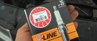
Spark plugs used on cars with ZMZ-405, 406 and 409 engines
Before you go to the store to buy spark plugs (SZ) for injector engines 405, 406 or 409, you need to read the service book for the car. The manual must clearly indicate the SZ models, the operation of which is allowed in such motors. The manufacturer officially recommends using SZ A14DVR or their analogues. If you decide to give preference to analogues, then keep in mind that the spark gap in the spark plugs should be 0.7-0.85 mm.
Some motorists, leaving reviews on the Internet, recommend using the SZ A17DVRM, but this is not allowed for two reasons:
- first of all, these products have a different heat dissipation parameter;
- In addition, their gap is 1 mm, and this is not suitable for these engines.
Finding A14DVR devices today is not so easy, so many car enthusiasts have to look for analogues.
So that you can choose a similar product, we suggest that you familiarize yourself with the decoding in more detail:
- A - this beech determines the diameter, as well as the pitch of the thread D. The original SZ uses an M14 * 1.25 thread.
- 14 is the value of the heat number. It is considered one of the main parameters that determine the characteristics of the temperature regime of the product.
- D is the value of the thread length. In our case, the SZ are equipped with a thread 19 mm long.
- B - determines how much the thermal cone of the insulator protrudes into the combustion chamber of the motor itself. Thanks to the protrusion of the cone, the product warms up faster when starting the power unit, and this, in turn, ensures its higher resistance to soot formation.
- The last symbol - P - determines the presence of a built-in resistor element in the SZ design. Thanks to the presence of a resistor, the level of interference for radio equipment, as well as the motor control module, is reduced. In general, the presence or absence of this element in the design of the SZ will not in any way affect the functionality and quality of spark formation when starting the internal combustion engine.
Replacement intervals and signs of malfunction
On average, the service life of modern SZ is about 20 thousand kilometers. Of course, this indicator depends on many conditions. First of all, this is the quality of the completed part, its operating conditions, as well as the quality of the fuel used. The last point is very important, since the use of low-quality fuel will lead to a significant reduction in the service life of the SZ.
What are the signs of faulty spark plugs?
- If you remove the SZ from its seat, you will see its body. The presence of soot and deposits on the device body, in particular on the electrode, may indicate a breakdown of the product. You can try to solve such a problem by cleaning, but this does not always help.
- Presence of oil traces on the SZ. Due to oil exposure, the product cannot work efficiently, so problems may occur in the operation of the SZ. Such devices need to be cleaned and dried, but before further use it is necessary to determine the reason for the contact of motor fluid with them.
- Also, fuel traces on the devices may indicate a malfunction of the SZ.
- Another sign is that the starter has to be turned for a long time, and the engine may start after a long period of time, or may not start at all. The same symptoms indicate a dead battery, a broken distributor, or an incorrectly functioning fuel pump.
- When the engine warms up, unpleasant and uncharacteristic sounds appear. They may also appear when idling.
- Fuel consumption during vehicle operation has increased significantly.
- In addition, the volume of harmful substances in exhaust gases has increased. Of course, this malfunction cannot be determined by eye; a more thorough diagnosis is required.
- The vehicle's traction has weakened significantly, its power has decreased, and the engine has difficulty picking up speed.
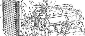
Sensors of the UAZ Patriot engine management system
The UAZ Patriot coolant temperature and air temperature sensors in the intake pipe, type 19.3828, are a thermistor (a resistor whose resistance changes depending on the temperature).
The coolant temperature sensor is screwed into the thermostat housing and connected to the controller input, which is connected to an internal 5 V source through a 2 kOhm resistor. At low temperatures the sensor resistance is high, at high temperatures it is low. The controller calculates the coolant temperature based on the voltage drop across the sensor. On a cold engine the voltage drop is high, on a warm engine it is low. Coolant temperature affects most of the characteristics controlled by the controller. To replace the UAZ Patriot temperature sensors for coolant and air temperature in the intake pipe, you will need a 19 key. Disconnect the wire from the minus terminal of the battery and partially drain the coolant from the radiator
Disconnect the wiring harness block from the sensor connector by unfastening the spring lock and unscrew the sensor from the thermostat housing
And the air temperature sensor from the intake manifold
Checking the UAZ Patriot temperature sensor circuit: 1 – variable resistance 10 kOhm; 2 – battery; 3 – voltmeter; 4 – milliammeter; 5 – sensor.
To test the sensors, you need to assemble a circuit. Using resistance 1 using milliammeter 4, set the current in the circuit to 1–1.5 mA. At a temperature of +25 °C, voltmeter 3 should show a voltage of 2.957–3.022 V. By changing the ambient temperature of the sensor, measure the value of the voltage drop with voltmeter 3. For a working sensor, it should be within the following limits: at a temperature of 40 °C – 2.287–2.392 V; at a temperature of 90 °C – 3.642–3.737 V. Replace the faulty sensor. Install the Patriot temperature sensors in the reverse order of removal. When installing the coolant temperature sensor, lubricate its threads with sealant
Crankshaft position sensor UAZ Patriot
The crankshaft position (synchronization) sensor type DG-6 0261210113 from Bosch or 23.3847 inductive type is designed to determine the angular position of the engine crankshaft, synchronize the operation of the controller with the engine operating process and determine the crankshaft rotation speed.
UAZ Patriot crankshaft position sensor diagram: 1 – sensor winding; 2 – body; 3 – magnet; 4 – seal; 5 – drive; 6 – mounting bracket; 7 – magnetic circuit; 8 – synchronization disk.
Structurally, the sensor is a bar magnet 3 on which winding 1 is mounted. When the teeth of the synchronization disk 8 pass past the end of the magnet, a potential arises at the winding terminals, which is information for the controller about the crankshaft speed. Two teeth on the disk are missing; when the cavity on the disk passes past the magnet, a pulse is generated, by which the controller determines that the piston of the 1st cylinder is at TDC.
If the timing sensor or its circuits fail, the operation of the ignition system and, consequently, the engine stops. The sensor can first be checked directly on the engine. For final inspection, the sensor must be removed from the engine. To replace the Patriot crankshaft sensor you will need: a thin screwdriver, a 10mm wrench, and an auto tester. Turn off the ignition and disconnect the wire from the negative terminal of the battery
Press the spring clamp of the block and disconnect the synchronization sensor connector, then connect one probe of the tester, turned on in ohmmeter mode, to the central terminal of the sensor wiring harness block, and the second probe to any side terminal. The sensor winding resistance should be 700–900 Ohms
For a final check, remove the sensor by bending the clamps securing its wiring harness to the intake pipe and cylinder block, pull the harness down, unscrew the mounting bolt and remove the sensor from the hole in the engine cylinder block
Connect a tester turned on in voltage measurement mode to the sensor terminals. Quickly bring a metal object (such as tweezers) to the sensor core. If the sensor is working properly, there will be a voltage surge on the device. If the voltage does not change, the sensor is faulty and needs to be replaced. Install the UAZ Patriot crankshaft sensor in the reverse order of removal. After installing the sensor, check the gap between its core and the teeth of the timing disk. It should be 1–1.5 mm.
Camshaft position sensor UAZ Patriot
Camshaft position sensor (phase sensor) type PG-3.1 0232103006 Bosch, or 406.3847050-04, or 406.3847050-05, or DF-1 is installed in the left rear part of the cylinder head. Its action is based on the Hall effect. Using the information from this sensor, the controller determines the moment when the piston of the 1st cylinder is installed at TDC of the compression stroke to calculate the fuel injection sequence according to the operating order of the cylinders.
If the Patriot valve timing sensor fails, the controller turns on a warning light in the lamp block and switches from the phased injection mode to the backup mode of supplying fuel to all cylinders simultaneously. In this mode, fuel consumption increases significantly, so a faulty phase sensor must be replaced as soon as possible.
To replace the sensor you will need: a thin screwdriver or an awl, a 10mm key. Turn off the ignition and disconnect the wire from the negative terminal of the battery
After unfastening the spring lock, disconnect the connectors of the phase sensor wiring harness. Remove the sensor wiring harness block from the metal holder
Unscrew the mounting bolt and remove the sensor from the hole in the cylinder head
Scheme for checking the Patriot phase sensor: 1 – sensor; 2 – plug block; 3 – resistor 0.5–0.6 kOhm; 4 – LED AL307; 5 – metal plate.
Assemble a circuit to test the Patriot camshaft sensor and connect the wires to the battery terminals. LED 4 should light up and go out immediately. Move tweezers or a screwdriver near the sensor rod. If the sensor is working properly, the LED should light up briefly. If the LED does not light, the sensor is faulty and must be replaced. Install the sensor in the reverse order of removal.
Air flow meter UAZ Patriot
The UAZ Patriot mass air flow sensor type HFM5-4.7 0280218037 from Bosch, or 20.3855 from Siemens, or 406.1130000-01 is located between the air filter hose and the intake pipe hose. The sensor signal is a DC voltage whose value depends on the amount and direction of air flowing through the sensor. The sensor has a built-in air temperature sensor, the sensitive element of which is a thermistor installed in the air flow. At low temperatures the sensor resistance is high, at high temperatures it is low
Air temperature sensor resistance versus intake air temperature
If the Patriot air temperature sensor is faulty, the controller stores an error code in memory and turns on the warning light; the controller replaces the readings of the faulty sensor with a fixed air temperature value of 33 °C. To replace the sensor you will need: a 10mm wrench, a Phillips-blade screwdriver. Disconnect the wire from the negative terminal of the battery
Using a screwdriver or finger, press the plastic latch from below and disconnect the wiring harness block from the mass air flow sensor. Loosen the hose clamps
Remove the hoses from the sensor, and then the UAZ Patriot air flow sensor. Install the sensor in reverse order. Pay attention to the condition of the rubber gasket, as damage to it can lead to interruptions in engine operation.
Throttle position sensor UAZ Patriot
The throttle position sensor type 406.1130000-01 or DKG-1 0280122001 manufactured by Bosch is a potentiometer with a current-collecting element moving along the radius of the current-carrying sector from 0 to 100°. To check the Patriot throttle position sensor you will need: an auto tester and a screwdriver. Disconnect the wire from the negative terminal of the battery
Disconnect the wiring harness block from the sensor and measure the resistance between terminals “1” and “2” of the sensor block. For a working sensor it should be about 2 kOhm. Connect the autotester to pins “2” and “3”. When the throttle valve is open, the resistance should be 0.7–1.38 kOhm, when closed - 2.6 kOhm
To replace a faulty Patriot throttle position sensor, remove the two screws securing it and remove the sensor. Install the new sensor in the reverse order of removal.
It will be useful: Deflectors on a Chevrolet Cruze: replacement
Knock sensor UAZ Patriot
Knock sensor 02612311046 made by Bosch, or GT 305, or 18.3855 is installed on the engine block on the right side under the intake manifold in the area of the 4th cylinder.
Patriot knock sensor diagram: 1 – plug; 2 – insulator; 3 – body; 4 – nut; 5 – elastic washer; 6 – inertial washer; 7 – piezoelectric element; 8 – contact plate.
The knock sensor on the Patriot is a piezoelectric device that senses vibrations in the block wall caused by shock waves during detonation in the cylinders. Detonation is the explosive self-ignition of the working mixture in the engine cylinders. During detonation, voltage pulses are generated at the sensor output, which increase with increasing intensity of detonation impacts. The controller, based on the sensor signal, adjusts the ignition timing to eliminate fuel detonation flashes. If the sensor or its electrical circuits fail, the controller signals the driver by turning on the lamp and switches to a backup engine control mode with a late ignition timing. This mode is characterized by reduced engine power and increased fuel consumption, so the sensor must be replaced as soon as possible. To check, you need to remove the knock sensor from the car.
To remove and check the knock sensor you will need: a thin screwdriver or awl, a key number 13. Turn off the ignition and disconnect the wire from the negative terminal of the battery
Remove the heater hose from the holder on the sensor bolt. Disconnect the wiring harness connector from the sensor terminals by unfastening the spring lock of the block
Unscrew the nut, remove the heater hose bracket from the stud screwed into the wall of the cylinder head, and remove the sensor from the stud. Connect an autotester turned on in voltage measurement mode to the sensor terminals. Tap the sensor body with a hard object (for example, tweezers) - the voltage should change. If the voltage remains constant, the sensor is faulty and needs to be replaced. Install the UAZ knock sensor in the reverse order of removal.
Lambda probe UAZ Patriot
The Patriot oxygen concentration sensor type 5WK9-1000G from Siemens is used in a fuel injection system with feedback. The sensor is installed in the exhaust pipe of the exhaust gas system. To adjust the calculations of the duration of injection pulses, information about the presence of oxygen in the exhaust gases is used; this information is provided by the oxygen concentration sensor. The oxygen contained in the exhaust gases comes into contact with the oxygen concentration sensor, creating a potential difference at the sensor output. It varies from approximately 0.1 V (high oxygen - lean mixture) to 0.9 V (low oxygen - rich mixture). For normal operation, the temperature of the sensor must be at least 300 °C, therefore, for rapid warming up after starting the engine, a heating element is built into the sensor.
By monitoring the output voltage of the Patriot lambda probe, the controller determines which command to adjust the composition of the working mixture to send to the injectors. If the mixture is lean (low potential difference at the sensor output), then the controller gives a command to enrich the mixture; if the mixture is rich (high potential difference) - lean the mixture. To replace the control oxygen concentration sensor, you will need a 22 key. Disconnect the wire from the minus terminal of the battery
Disconnect the sensor block and the wiring harness by pressing the plastic latch, then unscrew the sensor from the exhaust pipe and remove it from the car. Install the sensor in the reverse order of removal.
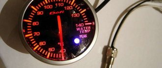
Signs of malfunction of coolant temperature sensors: top common causes
This element is often a headache for drivers: if the engine temperature rises and the engine does not cool, then first of all it is necessary to check the functionality of the TOZ sensor. Factors that precede the breakdown of the antifreeze temperature indicator in the engine are:
- Text on the car’s on-board computer and the check lamp on the dashboard lights up;
- Flashing of the temperature sensor warning lamp on the instrument panel;
- Problem starting the engine, despite the degree of warm-up of the power unit or the ambient temperature;
- A sharp change in exhaust gases in the engine;
- Difficulties when restarting the power unit;
- Spontaneous engine stalling, regardless of its load level;
- Increased fuel consumption.
If your car clearly shows one or more problems from the list, it is recommended to diagnose the TOZ indicator in the near future.
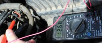
To do this, you need to visually inspect the part, and also check the assembly with a multimeter: the standard indicator voltage should be 1.5 V on a cold engine and 1.25 V when the power unit reaches operating temperature. In other cases, this element should be recognized as faulty and preparations should be made to replace the structural unit.
Important to remember! It is necessary to check the functionality of the TOZh sensor only if the power unit has completely cooled down. Also, before dismantling the indicator, it would be a good idea to check its wiring for corrosion or broken contact.
Temperature sensor ZMZ 409
I would like to dwell in more detail on the DTOZH for the E-3 and E-4 engines. Unlike sensors E-0, E-2, in this case there is a good alternative to Russian sensors. Sensors from imported manufacturers (Bosch, Febi, Vernet). Their big advantage is the following. All temperature sensors have a certain time delay in readings. For good imported analogues, this parameter is almost two times lower. And if the engine does not have a viscous coupling, but fans, then this parameter becomes very, very important. Unfortunately, I don’t know any imported analogues, DTOZH ZMZ 406 for E-0, E-2. I had to get rid of it as soon as possible. In particular, I took several sensors, gave them to a turner at the factory, and he reduced the wall thickness to the thermoelement as much as possible. This certainly has an effect.
Important. After the temperature sensor ZMZ 409, 405 (especially E-3, E-4) has been replaced, it is highly advisable to carry out the “reset and initialize the ECU” procedure. This can be done either using the on-board computer, or by connecting diagnostic equipment.
Source
Purpose:
The coolant temperature sensor (abbreviated as DTOZH) is a very important element responsible for the coolant temperature of the cooling system. The essence of its work is to give a signal to the engine control unit, which regulates the composition of the fuel mixture, as well as the crankshaft speed, as well as the ignition timing. Without this sensor there can be no talk about the correct functioning of the cooling system. The coolant temperature sensor transmits fluid temperature data (antifreeze, antifreeze or water) to the electronic control unit (ECU). And the temperature of the liquid that the driver sees on the dashboard is transmitted by another sensor, also a temperature one.
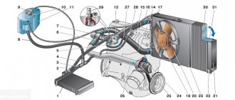
Electrical diagram of the UAZ-31512 car | AUTOFIZIK.RU / auto repair
1 — front light; 2 — headlight; 3 — sound signal;
4 — connecting block; 5 — side direction indicator; 6 — additional resistance; 7 — heater switch; 8 — heater fan electric motor; 9 — engine compartment lighting; 10 - generator; 11 — direction indicator relay; 12 — spark plugs; 13 — ignition coil; 14 — starter relay; 15 - starter; 16 — ignition distributor sensor; 17 - switch; 18 — battery; 19 — electric windshield washer; 20 — windshield wiper; 21 — “mass” switch; 22 — portable lamp socket; 23 - emergency vibrator; 24 - fuse block; 25 — oil pressure indicator sensor; 26 — coolant temperature sensor; 27 — coolant overheat warning lamp sensor; 28 — emergency oil pressure warning lamp sensor; 29 — switch for the emergency signal lamp of the hydraulic brake drive; 30 — parking brake warning lamp switch; 31 — brake signal switch; 32 — voltage regulator*; 33 — foot light switch; 34 — parking brake warning lamp; 35 — signal lamp of direction indicators; 36 — warning lamp for emergency condition of the hydraulic brake drive; 37 — horn switch; 38 — carburetor microswitch; 39 — electromagnetic valve of the EPHH system; 40 — block of the EPHH system; 41 — windshield wiper and washer switch; 42 — speedometer; 43 — warning lamp for emergency oil pressure; 44 - warning lamp for coolant overheating; 45 - central light switch; 46 — alarm switch; 47 — fuel level indicator; 48 — coolant temperature indicator; 49 — oil pressure indicator; 50 - ammeter; 51 — signal lamp for high beam headlights; 52 — interior lamp; 53 — interior lamp switch; 54 — direction indicator switch; 55 — fuel level indicator sensor; 56 - thermal (bimetallic) fuse; 57 — fuel tank sensor switch; 58 — ignition switch; 59 — reverse light switch; 60 — rear light; 61 — trailer socket**; 62 — reversing light; 63 — license plate light.
What to replace
If a defect occurs in the sensor, it must be dismantled and replaced with a known good one. If it is not possible to purchase a new sensor, then you can temporarily install a homemade one. To manufacture it you will need some radio components:
- thermal resistance 10 kOhm;
- capacitor 0.1 µF;
- resistor 1.5 kOhm.
The temperature sensor must be soldered efficiently, since vibration may cause defects at the joints of the parts. A homemade temperature meter will have the same parameters as the factory one, intended for the StarLine alarm.
Device, operation:
The basis of the sensor is a semiconductor thermistor, i.e. a resistor that has a nonlinear temperature-dependent resistance . The solution is more than simple and reliable - depending on the resistance, you can monitor the antifreeze temperature in real time, continuously. Thermistors are made of cobalt or nickel. Materials have one very important property. As their temperature increases, the number of free electrons also increases, which means the resistance decreases.
There are 2 types of thermistors depending on the temperature coefficient:
- With a negative coefficient . When the engine is cold, resistance is maximum. As soon as a voltage of 5 Volts is applied to the sensor, this value will decrease as it operates and the resistance changes. At the same time, the engine control unit records the voltage drop, thereby determining the temperature of the coolant poured into the system;
- With a positive coefficient . The sensor works the same way, but as the temperature rises, so does the resistance. Renault cars are equipped with such thermistors.
What temperature sensor is on the Patriot?
How does the coolant temperature sensor work?
———————————————————–
Before we move on to discussing how to check the coolant temperature sensor, it is necessary to briefly look at the signs of its malfunction and understand how it works. This will help determine the diagnosis. As mentioned above, the coolant temperature sensor (sometimes simply called the engine temperature sensor) is a thermistor - a resistor that changes its resistance depending on changes in temperature, in particular the coolant of the engine cooling system. The corresponding resistance value and its change are recorded by the electronic engine control unit (abbreviated as ECU), on the basis of which it issues the appropriate commands.
Finally, about the verification method
To perform a proper product check, you will need to acquire the following devices and accessories:
- Multimeter or regular voltmeter. Using these devices, it will be necessary to measure the voltage at the terminals of each sensor.
- Battery (12 V).
- A rheostat, which, after connecting with the battery, will produce a sensor supply voltage reduced to 5 Volts.
- An ammeter for measuring current.
Having assembled a simple diagram, we check the level of readings of the indicated parameters and compare them with the regulatory readings.
Below you can see a diagram of the connections of all components for checking the sensors.
Reasons for premature failure of DTOZH, DVTV
- Mechanical damage;
- Manufacturing defect;
- Crack on the body;
- Short circuit in the circuit;
- Loose terminals;
- Moisture getting inside measuring instruments;
- Burnout of the fuse melting element of the fuse box;
- Incorrect operation of the system firmware of the electronic control unit of the ECU.
Instructions for connecting short circuit
The ZMZ 405, 406 and 409 engines use two short circuits - one of them works with cylinders 1 and 4, and the second with cylinders 2 and 3. The first of them is located closer to the intake manifold, and the second is located next to the exhaust manifold. To make the connection correctly, low voltage wires should be connected in pairs - those used for the first coil (cylinders 1-4) will be shorter in length. Since the short circuits themselves are not polar, it does not matter which contact the cable will be connected to; it also does not play a role within the pair to which cylinder the wire will be connected (the author of the video is the SpawnyXC90 channel).
Basic aspects of ignition installation
The main aspects to consider when installing the ignition by marks:
- First, you need to dismantle the front cylinder head cover; to do this, you need to unscrew four 12-point screws. In some engine modifications, dismantling also involves removing the fuel pump.
- Then the upper hydraulic tensioner located in the head is dismantled; to do this, two screws securing the cover are unscrewed.
- Next, the chain stabilizers are removed - the middle one, as well as the top one; for this, the two screws that secure them are unscrewed.
- After this, the camshaft sprockets are dismantled. The shafts themselves need to be fixed using a 27 key, while simultaneously unscrewing the screws that secure them. In modifications of engines 4063.10, the camshaft sprocket is removed along with the fuel pump drive eccentric.
- In accordance with the jig installed on the sprocket, six holes should be drilled in each of them. Their angular displacements should be 2, 30, 5, 00, 7 and 30 degrees from the set position of the factory hole, which is located along the axis of symmetry.
- If, when adjusting the phases, it is necessary to turn the camshaft clockwise, the sprocket itself should be mounted on one of the additional holes with a positive offset. It is located to the right of the standard hole.