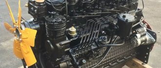
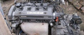
Minsk Motor Plant produces various internal combustion engines for buses, as well as industrial and agricultural equipment. The six-cylinder D 260 engine has excellent technical characteristics that are not inferior to the YaMZ-236 diesel engine. The 260 engine is characterized by increased endurance and performance. Its design allows the use of vehicles for a long service life without expensive major repairs.
Scope of application of the D 260 engine
Depending on the work performed, D 260 MTZ diesel engines are included with various additional equipment:
- pneumatic compressor;
- gear-type steering pump;
- clutch frictions;
- control sensors;
- cooling system radiator;
- elements of electrical equipment;
- starter;
- generator;
- turbocharger;
- fuel injection pump;
- oil pump;
- water pump, etc.
Most often, the D-260 diesel engine is installed on the following vehicles:
- Energy-rich wheeled tractors of the MTZ-1221 family.
- Grain harvesting equipment.
- Forage harvesters.
- Loaders (Amkodor 333V).
- Buses.
- Construction machines.
- Road equipment, etc.
Basic parts of the D-260 diesel engine
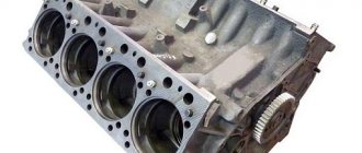
Cylinder block D-260
The cylinder block of the D-260 engine of the MTZ-1221 tractor is the main body part and is made in the form of a monoblock; it is a rigid cast iron casting. Six removable sleeves made of special cast iron are installed in the block bores.
The liner is installed in the cylinder block along two centering belts. In the upper belt the liner is secured with a collar, in the lower belt it is sealed with two rubber rings placed in the grooves of the cylinder block.
Coolant circulates between the walls of the cylinder block and the liners. The transverse partitions of the cylinder block have bosses designed to form supports for the crankshaft. Covers are installed on these tides.
The bosses together with the covers form beds for the main bearings. The beds for the main bearing shells are bored from one installation complete with covers. Changing covers is not allowed.
Diesel engine D-260 MMZ
1 – oil sump; 2 – oil pump; 3 – damper; 4 – crankshaft pulley; 5 – fan belt; 6 – distribution cover; 7 – tension pulley; 8 – nozzle for cooling the piston; 9 – fan; 10 – water pump; 11 – thermostat housing; 12 – connecting rod; 13 – piston; 14 – cylinder liner; 15 – cap; 16 cylinder head cover; 17 – cylinder head; 18 – cylinder block; 19 – back sheet; 20 – flywheel; 21 – crankshaft; 22 – oil receiver; 23 – camshaft.
The MTZ-1221 cylinder block has a longitudinal oil channel, from which oil is supplied through transverse channels to the main bearings of the crankshaft, and then to the camshaft journals and nozzles for cooling the pistons.
Piston cooling nozzles are installed in the cylinder block at the top of the second, fourth and sixth crankshaft bearings. On the water distribution channel of the cylinder block there is a platform for installing a liquid-oil heat exchanger. The supply and removal of oil from the heat exchanger is carried out through channels in the block.
To increase rigidity, the lower plane of the cylinder block of the D-260 engine is shifted downward by 80 mm relative to the axis of the crankshaft.
A steel distribution board and distribution cover are attached to the front end of the block, and a steel sheet is attached to the rear end, through which the diesel engine is connected to the frame of the MTZ-1221 tractor. The front support of the diesel engine is provided by two brackets mounted on the side surfaces of the cylinder block. The bottom of the cylinder block is closed by an oil sump.
Cylinder heads D-260
The D-260 cylinder head is cast from cast iron (one head for three cylinders) - interchangeable. In the internal cavities of the cylinder heads there are inlet and outlet channels closed by valves.
To ensure heat removal, the cylinder heads have internal cavities in which coolant circulates. The cylinder heads have inserted valve seats made of a heat-resistant and wear-resistant alloy.
The cylinder heads of the MTZ-1221 tractor are equipped with injectors (3 for each head), struts, rocker arm axles with rocker arms, head covers and cover caps that cover the valve mechanism. To seal the connector between the heads and the cylinder block, a gasket made of asbestos-free fabric is installed.
Technical characteristics of the D 260 engine
A large number of different modifications have been created based on the D 260 diesel engine: D-260.1-305, 1S2-333, 1S-394, 1-306, 1-308, 1-339, 1-358, 1-372, 1-380, 1 -406, 1-407, 1-417, 1-443.
Specifications table:
| Engine displacement | 7.12 l. |
| Cylinder diameter | 110 mm |
| Piston stroke length | 125 mm |
| Cylinder firing order | 1-5-3-6-2-4 |
| Engine power | 155 horsepower |
| Number of crankshaft revolutions | 2100 rpm |
| Idle speed | 850 – 2260 rpm |
| Torque (max) | 622 N.m |
| Compression ratio | 16 |
| Engine weight | 710 kg |
| Dimensions | 130x70.5x111.8 cm |
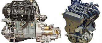
Engine D 245: Technical characteristics
The engine plant, located in Minsk, has produced more than one model of power plants during its existence, among which the D-245 engine has become widespread. The enterprise itself is known far beyond the borders of Belarus, since diesel units meet quality and reliability standards. In the CIS, the plant occupies a leading position in the design of diesel engines for combines, trucks and tractors.
Initially, the D-240 engine, used on the MTZ-80 (82) self-propelled units, was considered the leader in the field. The growing need for larger power units forced designers to develop a new product, which first appeared in 1984. Due to increased acceleration and power, versatility and survivability, diesel quickly became popular among consumers. The engine “got used to the role” and is therefore still produced today.
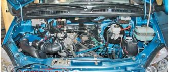
Installation "D-245. 12C" (ZIL-130):
Fuel system of the D 260 engine
The power system consists of the main elements:
- fuel pump;
- nozzles;
- piping systems;
- air purifier;
- manifolds (exhaust, intake);
- turbocharger;
- fuel filters;
- fuel tank;
- fuel injection pump;
- a fuel priming pump that supplies fuel from the tank to the injection pump cavity.
Diesel fuel is injected into the cylinders through special devices - nozzles equipped with a closed-type atomizing device. Fuel under pressure is evenly sprayed in the combustion chamber.
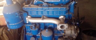
History of the D-245 engine
The year 1963 marked the beginning of the development of the motor industry in Minsk, when the creation of engines was established on the basis of the tractor workshop (MTZ). Initially, the goods were intended for domestic, agricultural use. As demand grew, the products were standardized and placed on trucks and harvesting equipment.
The first universal unit was the D-245, which replaced the D-240 in 1984. Operation with self-propelled units gave rise to modifications: the D245 2S2, (S2) engine, etc. And already in 1992, production of the D-245.1 variety began, intended for trucks such as the GAZ-3308 (081, 09) and others.
Structurally, the base is a row product with four chambers arranged vertically. The distribution shaft has five, not three, bearings, the pump supplies fuel using a different type of settings, this is the difference between the D 240 and D 245 engines. Otherwise, the indicators remained unchanged: the volume of the chambers is 4750 cm3, the operating order is “1342”. Together with fuel efficiency, the engine produces up to 164 horses and shows an impulse of 595 Nm. The unit weighs 560 kg, the engine is activated by a 12V electric starter.
Due to its popularity, reliable and durable performance, the engine was continued and today is produced in seven modifications. The 2021 version is adjusted to Euro-5 environmental standards, which made it possible to sell the product to European countries.
The procedure for adjusting engine valves D 260
The clearances are checked and adjusted after every 500 hours of working time. The gap sizes between the rocker arms and the D-260 valves must correspond to the following parameters:
- For intake valves – 0.25 mm.
- For graduation – 0.45 mm, respectively.
Sequencing:
- remove the cylinder head covers;
- check the degree of tightening of the fastening bolts;
- turn the crankshaft until the valve in the 1st cylinder closes;
- adjust the gaps in the following valves in order (count from the fan): 3, 5, 7, 10, 11, 12;
- turn the crankshaft one revolution;
- close the valve in the 6th cylinder;
- adjust the gaps in: 1st, 2, 4, 6, 8, 9 valves.
The adjustment process is carried out according to the diagram presented, where 1 is the adjustment probe, 2 is the adjusting nut, 3 is the screw.
Reliability, problems and repair of MMZ D-245
On top of the block is a modified cast iron head with different valve seats. The diameter of the valve plates is as follows: inlet - 48 mm, exhaust - 42 mm, stem diameter - 11 mm. The camshaft is installed in the block and rotates from the crankshaft through a gear; it acts on the valves using steel pushers, rods and rocker arms. Adjustment of valves on the D-245 is carried out as necessary; after every 500 hours of operation, you should check the condition of the gaps. It should be like this: inlet 0.25 mm, outlet 0.45 mm. The valve adjustment order is 1-3-4-2. Of course, it has its own intake, exhaust, fuel injection pump 4UTNI-T, a more powerful oil pump and a TKR-6 turbocharger (on the basic version).
In 1998, production of D-245 Euro-1 engines began. After another 3 years, Euro-2 versions were released, which differ in the crankshaft, pistons with a compression ratio of 17, cylinder head, YAZDA 773 fuel pump and TKR 6.1 turbine. ICE D-245 Euro-3 began to be produced in 2006 and they are distinguished by their piston, 42 mm piston pins, Common rail injection with a Bosch CP3.3 fuel pump and their own injectors. There is a TKR-6.5.1 turbine and a Bosch EDC7UC31 control unit.
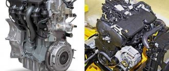
Design of the D-245 diesel engine
The main assembly units, systems, components and parts of the D-245 diesel engine are as follows:
- body (cylinder block and suspension);
- gas distribution mechanism (cylinder head, valves and valve lifters, cylinder head cover, exhaust tract (manifold), distribution mechanism);
- crank mechanism (pistons, connecting rods, crankshaft and flywheel";
- lubrication system (breather, oil sump, oil pump receiver and oil pump itself, oil filter with liquid-oil heat exchanger, turbocharger oil lines);
- power supply system (fuel pipelines and fuel equipment, fine and coarse filters, air cleaner and air exhaust tract);
- cooling system (pump, thermostat, fan).
In order to increase the technical and economic performance of the engine, turbocharging with intermediate cooling of the charge air was used in the intake system.
The addition of a turbocharger with adjustable boost pressure to the supercharging design made it possible to obtain better throttle response, which is ensured by an increased torque value at a low crankshaft speed; as well as the proper level of compliance with standards for the content of harmful emissions in exhaust gases. To guarantee uninterrupted engine starting at low outdoor temperatures, glow plugs are mounted in the diesel head, plus the liquid-oil heat exchanger available on these engines ensures that the optimal oil temperature in the lubrication system is quickly achieved, maintaining it at the desired level during operation.
Engine lubrication system D-245
The D-245 engine lubrication system is combined (Fig. 1): some parts are lubricated under pressure, others by splashing.
The crankshaft and camshaft bearings, the idler gear bushing, the connecting rod bearing of the compressor crankshaft, the valve drive mechanism (rocker arms) and the engine turbocharger shaft bearing are lubricated under pressure from the oil pump.
Sleeves, pistons, piston pins, rods, pushers, camshaft cams and fuel pump drive MTZ-892, MTZ-92P are lubricated by splashing. On diesel engines with a full-flow centrifugal oil filter installed, a diagram of the lubrication system in accordance with Figure 1a.
Fig. 1a - Lubrication system D-245
1 — oil sump; 2 – piston cooling nozzles; 3 - crankshaft; 4 - camshaft; 5 — intermediate gear; 6 — oil filler neck; 7 — oil sump plug; 8 — oil receiver; 9 — oil pump; 10 – oil radiator; 11 – pressure reducing valve; 12 – oil filter; 13 – bypass valve; 14 – safety valve; 15 – pressure sensor; 16 – turbocharger; 17 – compressor; 18 – high pressure fuel pump; 19 – oil channel of the rocker arm axis,
D-245 engine components
The D-245 engine, like other mechanisms, consists of elements. Each component is responsible for the assigned part of the work, the sum of which forms the functionality of the unit.
Core and head of chambers
Engine frame, the main load-bearing part of the engine in which the liners are installed. Parts are cooled using the open method, due to water flowing over the surface. Seals are provided to prevent leakage. The walls of the frame are used as supports for the shaft. The bottom of the support does not change, since it is made integral with the frame. The internal space is pierced by a channel through which lubricant is supplied under pressure to the loaded parts. Even supports with sprayers supplying oil to the bottom of the displacers. This feature maintains a balanced thermal regime, increasing the durability of the motor.
The material of the frame head is cast iron. To maintain the functionality of the motor, the product is equipped with valve guides and holes for mounting fuel nozzles. Mounting for the valve actuator and seat is also provided. The side surfaces of the product have channels for supplying the fuel mixture and exhaust gases. The inner part of the head with ducts through which cooling liquid flows from the frame. To prevent fluid leakage, a seal is provided.
Crank mechanism
The diesel unit is equipped with a crankshaft made of steel. Reliable fixation inside the unit occurs due to supports (5 pieces); movement along the axis is limited by a stopper. To balance the mechanism, a weight is attached to the product. The rear end is equipped with a flywheel made of cast iron with a toothed notch, through which the motor is activated. Displacers with a built-in combustion chamber to obtain an effect when releasing energy. The valves are driven by a shaft located below, the pressure is transmitted through pushers. The drive is carried out by the main shaft through gears. The gears are equipped with marks that help regulate the opening and closing of the valves.