Idle air control (IAC)
Idle speed control
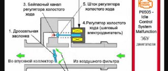
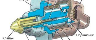
The idle air control (IAC) serves to maintain the set engine speed at idle by changing the amount of air supplied to the engine when the throttle is closed. The IAC is located on the throttle pipe and is an anchor-type stepper motor with two windings. When an impulse is applied to one of them, the needle takes one step forward, and to the other, a step back.
Through a worm gear, the rotational movement of the stepper motor is converted into a linear movement of the rod. The conical part of the rod is located in the air supply channel to provide control of the engine idle speed. The regulator rod extends or retracts depending on the control signal from the controller.
The idle speed control regulates the idle speed of the crankshaft by controlling the amount of air supplied bypassing the closed throttle valve. In the fully extended position (the fully extended position corresponds to “0” steps), the conical part of the rod blocks the air supply bypassing the throttle valve. When opening, the valve provides air flow proportional to the movement of the stem (number of steps) from its seat. A fully open valve position corresponds to 255 steps of stem movement. On a warm engine, the controller, by controlling the movement of the rod, maintains a constant crankshaft speed at idle, regardless of the engine condition and load changes.
In Mikas systems, a slightly different name is more often used - Additional Air Regulator (ADV). The RDV has a different design: instead of a stepper motor, a torque motor is used, which rotates the locking element at a certain angle proportional to the voltage.
Supply voltage range V: 7.5-14.2 for РХХ212-1148300-02 (Produced by KZTA) and РХХ212-1148300-01 (Produced by Pegas OJSC, Kostroma)
Testing
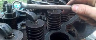
Turn off the ignition. Disconnect the harness connector from the regulator. Using a multimeter, check the resistance of the IAC windings. The resistance between the contacts of the idle air control system A and B, and C and D should be 40-80 Ohms. If not, replace the IAC. If yes, check the resistance between contacts B and C, A and D. The device should show infinity (open circuit). If not, replace the IAC. If so, the IAC circuit is ok.
Crankshaft sensor VAZ-2114
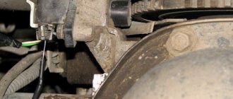
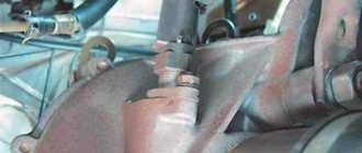
The crankshaft sensor is installed on the oil pump cover at a minimum distance from the drive disk of the mechanism. Information coming from the position meter in which the crankshaft is located is received by the engine control system, through which the injection and ignition system is controlled.
You can replace almost all types of sensors installed on a VAZ-2114 car yourself, with your own hands; for this it is not necessary to take the car to a car service center. Watching the video will give you a clearer idea of the idle speed sensor.
Mass air flow sensor
Mass air flow sensor
BOSH 0 280 218 004, 037, 116
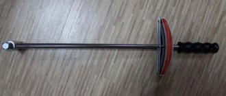
To assess the condition of the sensor with acceptable accuracy, you need a few minutes, a 10-mm open-end wrench, a shaped screwdriver and a Chinese tester with a fresh battery.
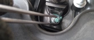
1. Turn on the tester in DC voltage measurement mode and set the measurement limit to 2 Volts. We find in the sensor connector a yellow wire - output (closest to the windshield) and a green wire - ground (third from the same edge).
These are the sensor pins we need. In systems of different years, colors may change (! and the connector may already be changed), only the location of the pins remains unchanged. To assess the condition of the mass air flow sensor, it is necessary to measure the voltage between the indicated terminals with the ignition on, but NOT starting the engine!
The diameter of the tester probes allows you to penetrate through the rubber seals of the connector, along the specified wires, without disturbing their insulation, reaching the contacts themselves and without causing harm to the seals themselves. It will be useful to spray HP grease on the probes. Turn on the ignition, connect the tester, take readings. The same readings can be taken without a tester from the on-board computer display, if anyone has one. In the “voltage from sensors” parameter group. Designated Udmrv=…
2. Evaluate the results. The voltage at the output of a working sensor in the out-of-package state is 0.996…1.01 Volts. During operation, it gradually changes and, as a rule, increases. By increasing this voltage, one can quite confidently judge the degree of “wear” of the sensor. A voltage within the above range is the best result of this test.
The following are possible options:
- 1.01…1.02 is a completely working sensor, very good.
- 1.02…1.03 is also acceptable, but the sensor is no longer young.
- 1.03…1.04 - most of the resource is already behind, you can plan for a quick replacement.
- 1.04…1.05 - clearly a tired sensor, it has already served its purpose. If your budget allows, feel free to change it.
- 1.05...and higher are a source of problems, it’s high time to replace them.
3. If, according to the assessment results, the sensor has deviations, and in general, even if it does not, but since we have already gotten around to it, we carry out a visual inspection. Using a figured screwdriver, unscrew the clamp of the rubber corrugation-air intake at the sensor outlet, pull off the corrugation from it, and carefully inspect the internal surfaces of both the sensor itself and the corrugation.
Attention! These surfaces must be dry and clean like... a baby's, without traces of condensation and oil! Their contact with the sensitive element of the sensor is the most common cause of its premature death. This happens both because the oil level in the crankcase is too high, and because the oil sump of the crankcase ventilation system is clogged, the outcome is usually the same. If this phenomenon occurs in the intake tract, replacing the sensor is contraindicated! Until the causes are eliminated, so that there is no excruciating pain later for wasted money.
4. Using a 10mm wrench, unscrew the 2 screws securing the sensor to the air filter housing and remove the sensor. On the front of it, on the inlet edge, which has just been removed from the filter, there must, by law, be a rubber sealing ring. It serves one purpose - to prevent the suction of unfiltered air into the intake tract through the sensor and further into the piston group.
As a rule, the ring is not in place - it is stuck in the air filter housing and is avoiding its direct responsibilities. This can be confirmed by a thin layer of dust on the input grid of the sensor itself. We run our finger over it and draw conclusions. If the rubber band was in place, we draw conclusions about its elasticity or the quality of the air filter. Another reason that kills the sensitive element!
We take out the ring and restore the legality of the assembly. The ring has a sealing belt-skirt on the inner surface. When assembling, make sure that it does not curl up, which is also a source of dust. I understand about the air filter. The assembly, with the exception of the sealing rubber, is not tricky - first put it on the sensor, check the sealing skirt, then put it all together into the filter housing. Then the sensor enters the filter housing with noticeable force. We tighten the screws.
The described method is not exhaustive and absolute, but within the framework of an amateur express check it is quite worthy of attention. A more accurate method is only possible if you have professional equipment.
DTOZH (Coolant Temperature Sensor)
DTOZH
It is a thermistor, i.e. a resistor whose electrical resistance changes depending on temperature. The thermistor located inside the sensor has a negative temperature coefficient of resistance, i.e. When heated, its resistance decreases.
High temperature causes low resistance (70 ohms at 130 degrees) of the sensor, and low coolant temperature causes high resistance (100800 ohms at -40 degrees).
When replacing the sensor, do not forget to unscrew the valve cap from the expansion tank of the cooling system to relieve pressure. Dependence of the resistance of the coolant temperature sensor on temperature (approximately).
Temperature - Ohm resistance:
Well, accordingly, we all know how to use a tester. So measure the resistance.
DPKV (Crankshaft Position Sensor)
DPKV
The ECU installed on injection cars, controlling sensors and actuators, for correct and efficient operation must know exactly what position the engine crankshaft is in at every moment of time - in other words, have clear synchronization between the digital and the hardware.
This is necessary, first of all, for calculating and timely supplying the injection pulse to the injectors and the explosive discharge to the spark plugs. The power, durability and efficiency of the engine depend on the timeliness of these events, so the need for the control unit to accurately determine the crankshaft position at any time is beyond doubt. Synchronization is carried out using a crankshaft sensor (CPS) and a toothed drive disk mounted on the crankshaft in a certain position.
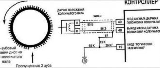
There are 60 teeth placed on the circumference of the disk, each tooth accounts for (360:60) = 6 degrees of crankshaft rotation angle. But there are deliberately no two teeth in a row in one place; their absence creates a gap. Total 58. The master disk is installed in such a way that after skipping two teeth by the DPKV core, as the crankshaft rotates, 114 degrees remain before TDC. Each tooth is 6 degrees. Total 114:6=19 whole teeth. In other words, when the crankshaft is in the TDC position of the first cylinder on the compression stroke, when all the marks (on the flywheel, camshaft\shafts) are combined, the crankshaft sensor should look at the beginning of the twentieth tooth after the skip, as the disk rotates.
Unfortunately, in practice this is not always the case. It happens that it cuts off a key on the crankshaft gear. Most often, not even the one that the arrow points to, but on the gear itself there is a cylindrical protrusion, which determines the position of the disk on the crankshaft gear. It happens that the thread in the CV itself is not completely cut, or is clogged at the end, and the fastening bolt does not press the disk with the required force to the crankshaft gear; sometimes the rubber damper of the pulley itself rotates, and the ring gear rotates relative to the CV. There is only one result: If the master disk moves at least 1 tooth relative to the HF, the ignition timing shifts by 6 degrees in all operating modes and the injection phase with all that it implies.
If you look at the drive disk from the side of the head of the fastening bolt and set the marks, the teeth will skip (if on a clock dial) by about 10 minutes (rotate the disk clockwise). Roughly speaking, at this moment he looks at the inspector under the hood. We check the accuracy of the marks and count the teeth from the skip around the circle counterclockwise. The crankshaft sensor core should look at the beginning of the 20th tooth. If so, the check is over.
1 – battery; 2 – ignition switch; 3 – ignition relay; 4 – spark plugs; 5 – ignition module; 6 – controller; 7 – crankshaft position sensor; 7 – crankshaft position sensor; 8 – master disk; A – matching devices
Operating range
The DPKV resistance in an injection engine should be between 550-750 Ohms.
Air sensor VAZ-2114
Modern environmental requirements for internal combustion engines are increased. That is why, in all modes of its operation, the established ratio of air to fuel in the air-fuel mixture must be maintained.
Only if these conditions are met will the catalytic converter completely remove harmful substances in the exhaust gases.
To maintain the stoichiometric ratio of the various components present in the fuel-air mixture, reliably accurate information on the amount of air consumed is required.
The air flow sensor installed on the VAZ-2114 is designed to collect air flow data. The measure of intake air flow can be calculated both in volume and in mass.
Today there are two types of air flow sensor: thermal and mechanical.
With the mechanical method, the incoming air is measured, which is proportional to the movement of the damper. The basis of the thermal method is to measure the mass of incoming air, which directly depends on the temperature of the sensitive element for a given period of time. The car's air flow sensor is installed between the throttle valve and the air filter in the intake system.
Ignition module
Ignition module
I’ll say right away: there are no simple tests that can reliably evaluate this element of the ignition system. For the reason that the spark formation process itself cannot be called simple. First, the accumulation of inductive energy in the coil, then saturation, breakdown of the spark gap, the occurrence of an arc, its combustion, and finally, damped oscillations.
Each stage has its own characteristics, characteristics and parameters, everything has its essence and weight. Changes in characteristic quantities: accumulation time, breakdown voltage, combustion voltage, arc burning time and distortion of the shape of damped oscillations provide a lot of information about the health of the coil or module.
All this is clearly visible on the monitor of a motor tester or oscilloscope, and deviations in individual cylinders are clearly visible in comparison. But according to the terms of this topic, we, like most car enthusiasts, have nothing except a control unit and a Chinese tester. Well, no need, we’ll try to get out of it, there are no hopeless situations. Actually, there are only 2 methods worth attention left: Determination of performance by the arrester and the simple replacement method. The first method is often used, but it involves having a spark gap itself, and is based on the fact that a working ignition module should be able to spark a 20mm air gap with any of its terminals. A defective module channel will not be able to do this.
Personally, I like the arrester design with an adjustable or 4-step gap of 5, 10, 15, 20 mm. By running the coil leads one by one, you can see when the weakest one gives up. I will not dwell on this in detail, the designs of arresters and descriptions of the method in the sea network. The method works, although it has certain limitations and requires some experience and skill. Therefore, I would like to focus on the second method - simple substitution, especially since it is the most accessible for car enthusiasts.
This is a really simple method, but there is one point. The ignition module is designed in such a way that it easily develops a voltage of 20 kilovolts at its terminals. When a control pulse is received from the control unit, a high-voltage discharge through explosive wires rushes to ignite the mixture compressed in the cylinder. Question. Where will the charge go if the wire is suddenly broken? (or will be completely absent - for the module this is the same thing) The discharge is looking for a way out, and unfortunately, it quickly finds it. Most often, the module pierces its own insulation with its own energy and begins to “sew” to ground along the shortest current path.
Where the insulation is weakest. The trodden path drains the charge energy onto the ground, as a result, 2 cylinders fail at once. Either 1-4 or 2-3, depending on which wire breakage triggered the insulation breakdown. The insulation may turn out to be good, then a breakdown is possible between the turns of the coil itself, again inside the module. Moreover, a breakdown can cause an interturn short circuit, or it can simply be sewn when the breakdown conditions, even on a serviceable wire, are the most severe. And these are moments of maximum load on the engine, for example, intense acceleration. Another question is which turns will close: if they are extreme, then the channel will fail.
And if they are adjacent, then the coil will lose power, and almost imperceptibly to the eye - the inductance is no longer the same. But this is for the time being. Soon, twitching, adjustments, jerks and dips, idle speed fluctuations, and other troubles will begin. These are not all types of module malfunctions, but the couple listed above indicate that its health largely depends on its operating conditions.
Therefore, in relation to our method, the question is: What will happen if, without checking the serviceability of the explosive wires, you install a known-good ignition module on your car as a replacement, kindly provided by a neighbor? (if one of the wires is broken, and the module is probably fried for this reason) Nothing may happen: your neighbor’s module may turn out to be more powerful than yours, and for the duration of a short test it will cope with the task, breaking through the gap, and you, making a mistake in diagnosis, buy a new one , which will not live long due to a broken wire.
In short, before checking the ignition module by replacing it, be sure to check the condition of the explosive wires. They can be not only the source of deterioration in driving performance, but also the cause of failure of the ignition module itself, which most often happens. Well, about the fact that it is impossible to check the serviceability of the coil and module while the engine is running by removing the explosive wires in turn from each spark plug, you cannot start or even crank the engine with the starter if at least one wire is removed from the module, you cannot use wires of dubious quality, you and so you know.
TPS (Throttle Position Sensor)
TPDZ
Mounted on the side of the throttle pipe and connected to the throttle shaft. The sensor (TPS) is a potentiometer, one end of which is supplied with a plus supply voltage (5 V), and the other end is connected to ground. From the third terminal of the potentiometer (from the slider) there is an output signal to the controller.
When the throttle valve is turned (by operating the control pedal), the voltage at the sensor output changes. To check the functionality of the sensor, measure the voltage at this contact with the damper closed. It should be within 0.3-0.7 V (0.7 is better).
When the damper opens, the voltage at the sensor output increases and when the damper is fully open it should be more than 4 V. By monitoring the sensor output voltage, the controller adjusts the fuel supply depending on the throttle opening angle (i.e. at the driver’s request). The throttle position sensor does not require any adjustment because the controller independently determines the minimum voltage of the sensor and takes it as the zero mark.
There are also new type CONTACTLESS sensors produced by the Kursk plant “SchetMash”. TU 4591-034-00225331-2002. Since 2003, these have also been installed.
Engine management system
In general, the entire engine control system consists of two components:
By “brains” we mean an electronic control unit, or in short “ECU”, “brains”, “computer”. As they were produced, injection VAZs were equipped with different ECU models - Bosch, January, Avtel/Itelma. To learn more about the brains, the main problems, which brains were installed in certain years, the possibility of chip tuning, read the detailed article - ECU. What it is?
The brains take readings of the current state from the sensors, analyze and control the operation of the engine using the same sensors.
Now let's talk about the sensors themselves that are involved in engine operation:
- Crankshaft position sensor (CPS) - serves to synchronize engine operation with the operation of the ECU, works on the principle of induction. In the event of a malfunction, the car does not start well, does not pull, ... More details in the corresponding article.
- Camshaft position sensor (CPR) - often called the “Phase sensor”. Serves to determine phased injection. It is possible to work with a faulty sensor. In details.
- Throttle position sensor (TPS), or gas pedal position sensor (if the gas pedal is electronic, installed since 2011). As for the DPZ, it is paired with the IAC. TPS determines the degree of opening of the throttle assembly. If this sensor is faulty, then there is no response to the gas pedal, the speed increases spontaneously, etc. More details in the corresponding article.
- Knock sensor (DS) - the name speaks for itself. The knock sensor detects engine vibrations (detonation) and accordingly advances the ignition angle. More details in the corresponding article.
- Coolant temperature sensor (Dtozh) - in other words, an engine temperature sensor. Installed on the thermostat, designed to control the temperature conditions of the engine. Read more about how to replace and check in the article.
- The mass air flow sensor (MAF) is the most expensive sensor, so its failure is extremely unpleasant. Using this sensor, the ECU reads the amount of air consumed. The main malfunctions are lack of traction from the engine, problems with idling. On this site, good informative articles are devoted to this sensor, which you can read.
- Speed sensor (DS) – the speed sensor is primarily designed to measure the speed of the vehicle and is located on the gearbox. But it also has other functions - more on that.
- Oxygen concentration sensor, or simply oxygen sensor (dk) - determines the amount of oxygen in the exhaust system, regulates the mixture of fuel and air. Euro-2 has 1 sensor installed, Euro-3 has two sensors. Very often, after 60 thousand km. The second mileage sensor is disabled by software because With our gasoline it quickly breaks down. However, it can be repaired and replaced. DC is also the cause of many problems, more about this.
- Idle air control (IAC) (until 2011) or an electrically driven throttle valve (since 2011) - this sensor is responsible for stable idling. Allows air into the engine at idle speed, bypassing the TPS. Quite a capricious sensor, we replace it often. The main problem is unstable idle. Often there is a marriage. More about this.
- Electric throttle valve - (E-gas) - the essence is that it is an electronic throttle valve, which is opened not by the gas pedal cable (mechanically), but by the brains (electronically).
- Gas pedal position sensor - (E-gas) - the sensor provides readings of the gas pedal position to the computer, which in turn opens the electronic throttle valve.
Speed sensor
Speed sensor
The operating principle of the speed sensor (DS) is based on the Hall effect. The sensor outputs voltage pulses to the controller with a frequency proportional to the rotation speed of the drive wheels. Speed sensors differ in the connection connectors to the harness block. The square connector is used in BOSCH systems.
The sensor with a round connector is used in the January 4 and GM systems. All sensors are 6-pulse, that is, they produce 6 pulses per revolution of their axis. The 10-pulse sensor is used for Samara carburetor trip computers. The speed sensor signal is used by the control system to determine the fuel cut-off thresholds, as well as to electronically limit the vehicle speed (in new control systems).
In those models that have one, you need to install the speedometer drive into the gearbox very carefully; at the slightest misalignment, the plastic teeth of the speedometer drive drive gear will wrinkle and complete disassembly of the gearbox is inevitable.
When the speedometer needle begins to spontaneously deviate within a fairly wide range, regardless of speed, it’s time to change the speed sensor.
The output voltage of the low level pulse should be no more than 1V, and the high level pulse should be no less than 5V.
Knock sensor
Knock sensor
A knock sensor is a device designed to determine the moment of detonation in internal combustion engines. It is one of the sensors of electronic engine management systems of vehicles with fuel injection.
There are two types of knock sensors - resonant (barrel) and broadband (tablet). Different types of knock sensor are not interchangeable.
The operating principle of the sensor is based on the piezoelectric effect. The sensor is attached to the engine cylinder block; when detonation occurs, the engine vibrates, leading to compression of the piezoelectric plate of the sensor, resulting in a potential difference at its ends.
Based on the electrical impulses of the sensor, the electronic engine control unit selects the optimal ignition timing, which allows for the most complete and efficient combustion of the fuel-air mixture in the engine cylinders, as well as automatically adapting to fuel with different octane numbers.
To check the knock sensor, we connect a tester to its contact and body.
By lightly tapping the threaded part of the sensor with a soft metal rod, we measure the voltage pulse. Depending on the intensity of the shock, a voltage pulse for a working sensor can reach 300 mV.
Mass air flow sensor (MAF)
The mass air flow sensor is located in the engine compartment of the VAZ 2114 and is one of the most recognizable car sensors. The mass air flow sensor is attached with two bolts to the air filter box. The mass air flow sensor is responsible for counting the air intake from the engine and transmits the readings to the above-mentioned ECU. The mass air flow sensor is directly related to the formation of the air-fuel mixture.
Signs of a DMRV malfunction:
- Deterioration of car dynamics;
- Increased fuel consumption;
- Floating speed at XX;
- When starting the internal combustion engine, you have to turn the starter for a long time;