All the main sensors in a car engine, and what they are responsible for (list)
With the advent of the fuel injection system, the number of sensors in the car design has increased significantly. The electronic engine control unit receives and processes a large amount of information, which is necessary for the proper operation of all systems. But not all drivers know what sensors are included in the car’s design and what they are intended for. I decided to talk about all the main elements, which will allow car enthusiasts to independently diagnose the problem.
Will the article be useful? Don't forget to give a "thumbs up"
and
subscribe to the channel
!
Let's move on to the list of sensors:
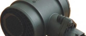
Mass air flow sensor (MAF)
— located behind the air filter and determines the amount of air passing through. Necessary for the formation of an optimal fuel-air mixture. Data from the mass air flow sensor is transmitted to the ECU, which adjusts the fuel supply in accordance with them.
Throttle Position Sensor (TPS)
— reads information about what position the throttle valve is in. The throttle position depends on the level of pressure on the gas pedal. Data from the sensor allows you to adjust the fuel supply volume.
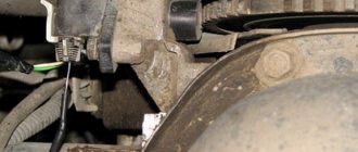
Crankshaft position sensor (CPS)
— reads the position and revolutions of the engine crankshaft.
Perhaps this sensor can be called the only one whose failure will lead to the complete impossibility of starting the engine
. Readings from the DPKV allow the ECU to determine the timing of fuel injection and the ignition timing. Information from the sensor is also displayed on the tachometer.
Camshaft position sensor (CPR)
- located in the camshaft area and allows you to determine the position of the cylinders at the top point. Data from the DPRV allows you to determine which cylinder needs to be supplied with fuel and turn on the ignition.
Knock sensor
— a sensor that detects detonation in the combustion chamber. Detonation puts a serious strain on the engine and can destroy it from the inside. The sensor detects excessive fluctuations, and when they occur, the fuel mixture and ignition timing are adjusted.
Coolant temperature sensor (DTOZH)
— determines the coolant temperature in the system. Data from the DTOZH allows you to warm up a cold engine faster due to increased idle speed, and when the set temperature is reached, the ECU turns on forced cooling with a fan to avoid overheating.
Oxygen sensor
- located in the exhaust system. Modern cars have two or more sensors. Their use is related to environmental standards. The first oxygen sensor is located in front of the catalyst, the second behind it. Depending on the readings, it allows you to adjust the fuel mixture and determine whether the catalyst is faulty.
Speed sensor
- usually located next to the gearbox or wheel. Determines the number of shaft rotations, due to which the ECU displays the current speed on the dashboard. Now its function can be replaced by other sensors, for example, an ABS sensor.
Oil pressure sensor
— located in the oil system and determines pressure. No parameters are adjusted based on it, but if the pressure is too low, the “oil can” light will light up on the dashboard.
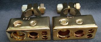
Absolute pressure sensor (MAP)
— reads pressure readings in the intake manifold, due to which the composition of the fuel-air mixture is adjusted.
Body position sensor (rough road sensor)
— located on the car body and allows you to determine movement on uneven roads. Since such a driving mode can lead to misfires, a characteristic error should light up on the dashboard. But the ECU understands that the car is driving over uneven surfaces, so it does not display an error.
Source
How does a position sensor work?
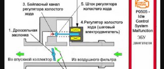
The principle of operation of DPKV depends on its type. The most common are inductive or magnetic. Let's look at their work step by step:
- On the reference (master) disk there is space for 60 teeth, but two teeth are missing in one place, so we end up with 58. The gap ensures synchronization of the sensor and is the beginning of the crankshaft rotation count.
- The sensor creates a magnetic field. As the drive disk rotates, its teeth pass through the magnetic field, creating pulses.
- When the area with missing teeth passes through the magnetic field, the device fixes the initial position of the crankshaft. All data is transmitted to the control unit.
- The computer determines the position of the crankshaft and the number of revolutions in accordance with the pulse frequency.
- As a result, the operation of the ignition system and the engine as a whole is corrected.
There are also 60-2-2 type 60-2-2 dual tooth 180° tooth drives which are used on some types of diesel engines.
Important! An inductive sensor does not use a supply voltage, and the electrical signal is generated by a magnetic field passing through the winding.
The principle of operation of an injection engine
An injection engine is a rather complex mechanism, the operation of which must be well tuned in order to get maximum performance from it.
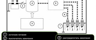
The center of the entire system is the ECU (electronic control unit).
It goes by many names, "brains", "computer" and so on.
Essentially, yes, it’s a computer that contains a huge number of tables on mixture composition, fuel injection time, and so on.
For example, if the engine speed is 1500, the throttle is open 10 degrees, and the air flow is 23 kg, then one amount of fuel will enter the cylinder. If the input parameters change, then the result will be different. If any problems arise with the control unit, for example, the firmware crashes, then everything goes to waste, the engine either starts to work haphazardly or stops altogether.
Coolant temperature sensor
The coolant temperature sensor is actually a semiconductor thermistor. The lower the coolant temperature, the greater the resistance. On the other hand, the lower the resistance, the hotter the antifreeze and, accordingly, the engine itself.
What function does the sensor perform: used to determine the temperature of the coolant in the engine. The electronic engine control unit adjusts the timing of fuel injection and ignition in accordance with the signal received from the coolant temperature. If the coolant temperature exceeds, the electronic system warns the driver of the danger of engine overheating. Thanks also to the sensor, the computer turns on the cooling fan when the coolant temperature begins to rise above the engine operating temperature.
Signs of Trouble: When the coolant temperature sensor fails (usually poor contact, short circuit, open circuit, but in most cases poor contact), a "Check Engine" . The coolant temperature gauge on the dashboard always shows a maximum of 120 degrees Celsius. In this case, the engine power and thrust drop significantly, since the engine control unit must turn on the emergency program (not available in all car models). When scanning for errors using a diagnostic scan tool, the electronic system reads a P003D fault code. Also, if the temperature sensor fails, the car may have difficulty starting when cold. In addition, abnormal fuel consumption may occur.
Injection engine sensors
All elements can be divided into actuators and sensors.
Mass air flow sensor (MAF)
This element is installed in front of the air filter, right at the inlet. Its operation is based on the principle of difference in readings. So, electricity passes through two platinum filaments. Their resistance changes depending on the temperature. One of the threads is reliably hidden from the air flow, which makes its resistance unchanged. The second one is cooled by the flow, and based on the difference in values, according to the same tables mentioned above, the ECU calculates the amount of air.
Engine absolute pressure and temperature sensor (DBP)
It is used either as an alternative or in conjunction with the above for higher reading accuracy. In short, it has two chambers, one of which is sealed and has an absolute vacuum inside. The second chamber is connected to the intake manifold, where a vacuum is created during the intake stroke. Between these cameras there is a diaphragm, as well as piezoelectric elements. They generate tension when the diaphragm moves. The signal then goes to the ECU.
Lecture No. 8 Automotive sensors
Rapid progress in the field of electronics and electrical engineering in recent years and decades has led to a sharp increase in the number of electronic components in a car.
Along with hydraulics and pneumatics, electronics have penetrated into every part of the car. Individual electronic components and complete electronic systems are becoming increasingly compact, cheaper and at the same time more efficient. As a result, new possibilities for using electronics in the car are emerging, allowing the scope of existing functions to be constantly expanded. Such progress inevitably affects the organization of service stations in the automotive sector. Routine jobs are reduced and the skills needed to perform them become less important. It is becoming increasingly important to obtain the necessary information through electronic means, understand the operation of complex systems and, ultimately, carry out correct diagnostics based on targeted control and measurement work. In this regard, another transformation must occur: a transition from thinking and understanding individual systems to complex thinking and understanding system relationships. Naturally, from now on, as before, knowledge and understanding of the operating principle and details of individual systems will remain important. At the same time, however, it is also necessary to know and understand the connections and connections with other systems. Electronic control systems of a modern car are unthinkable without sensors. Automotive sensors evaluate the values of non-electrical parameters and convert them into electrical signals. The signal is voltage, current, frequency, etc. The signals are converted into digital code and transmitted to the electronic control unit, which, in accordance with the programmed program, activates the actuators.
Sensors can be active or passive. In an active sensor, the electrical signal arises due to internal energy conversion. A passive sensor converts external electrical energy.
Sensors are used in almost all vehicle systems. In the engine they measure the temperature and pressure of air, fuel, oil, and coolant. Many moving parts of the car (crankshaft, camshaft, throttle body, transmission shafts, wheels, EGR valve) have position and speed sensors connected to them. A large number of sensors are used in active safety systems.
Depending on the purpose, the following types of automotive sensors are distinguished: position and speed, air flow, exhaust gas emission control, temperature, pressure.
Position and speed sensors
The linear or angular movement of the controlled object is converted into an electrical signal using position and speed sensors. The car uses sensors for crankshaft position, camshaft position, throttle position, fuel level, accelerator pedal position, wheel speed, steering wheel angle.
Position and speed sensors are made contact or non-contact. Although non-contact sensors are preferred, contact devices are still widely used. Despite all their advantages, contact sensors have one significant drawback - they are prone to contamination and, accordingly, reduce the accuracy of measurements.
Contact position sensors include potentiometers with moving contacts , which measure the linear and angular movements of an object. The moving contacts move along the length of the variable resistor and change its resistance proportional to the actual movement of the object. Potentiometers are widely used as throttle position sensor, gas pedal position sensor, air volume flow meter, fuel level sensor, etc.
The operation of non-contact position and speed sensors is based on various physical phenomena and effects, and the corresponding sensors: inductive, Wiegand, Hall, magnetoresistive, optical and many others.
The inductive sensor is widely used as a crankshaft position sensor. It contains a permanent magnet, a magnetic circuit and a coil. When a steel object (gear tooth) approaches the sensor, the magnetic field increases and an alternating voltage is induced in the coil. Unlike inductive sensors, Wiegand sensors do not use a permanent magnet, but are activated by an external magnet.
The most popular non-contact sensors are based on the Hall effect . The essence of the effect is that a permanent magnet connected to the measured object, when rotating, generates a voltage proportional to the angular position of the object. Hall sensors use several position and velocity measurement schemes: rotating chopper, multi-pole ring magnet, ferromagnetic gear rotor. To measure the angular velocity of a gear rotor, a differential Hall sensor is used - two adjacent measuring elements that allow you to see the tooth and cavity simultaneously.
The optical sensor uses a light-modulating disk with alternating transparent and opaque sectors to determine angular position. The disk is located between the LED and the photoresistor. When moving (rotating) the disk, electrical impulses are generated on the photoresistor, which determine the angle and speed of rotation of the shaft.
Air flow sensors
The air flow entering the engine is determined by volume or mass. Sensors that determine air flow by volume are called volumetric flow meters . The operation of such sensors is based on assessing the movement of the damper, which is proportional to the amount of air flow.
Exhaust emission sensors
Regulation of the content of harmful substances in exhaust gases is provided by emission control sensors, which include an oxygen concentration sensor and a nitrogen oxide sensor.
An oxygen sensor (another name is a lambda probe) is installed in the exhaust system and, depending on the oxygen content in the exhaust gases, produces a certain signal. Based on the signal, the engine control system maintains the stoichiometric composition of the fuel-air mixture (so-called lambda regulation).
On modern vehicles equipped with a catalytic converter, two oxygen concentration sensors are installed. An oxygen sensor at the outlet of the converter monitors its performance and ensures that the content of harmful substances in the exhaust gases is within the established standards.
The nitrogen oxide sensor monitors the content of nitrogen oxides in the exhaust gases. It is installed in the exhaust system of gasoline engines with direct fuel injection after an additional (storage) converter. The sensor includes two cameras. In the first chamber, the oxygen concentration is assessed. Secondly, the reduction of nitrogen oxides into oxygen and nitrogen occurs in the second chamber. The concentration of nitrogen oxides is estimated by the amount of reduced oxygen.
Actuators
The actuators got their name because they make adjustments to the operation of the engine. That is, the control unit receives a signal from the sensor, analyzes it, and then sends the signal to the actuator.
Fuel pump
Let's start with the power system. It is installed in the tank and supplies fuel to the fuel rail at a pressure of 3.2 - 3.5 MPa. This ensures high-quality fuel spray into the cylinders. As soon as the engine speed increases, the appetite also increases, which means more fuel must be supplied to the ramp to maintain pressure. The pump begins to rotate faster at the command of the control unit. Most modern cars, starting around 2013, are equipped with a fuel module, which includes a pump and a built-in filter. This significantly affects the cost of filter replacement, because the entire module must be replaced. Some manufacturers write in the instructions that the module is installed for the entire service life of the car, but you should not believe that any filter can last more than 2 seasons.
Nozzle
After the fuel has passed the entire circuit of the wire, it enters the nozzle, which meters its supply into the cylinder. The injector is a very small diameter solenoid valve that sprays gasoline into the combustion chamber. The ECU modifies the amount of fuel supplied by time intervals while the injector is open. As a rule, this is tenths of a second.
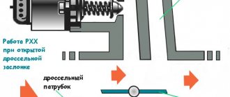
Idle air control (IAC)
This is also an electromagnetic valve, the rod of which closes the air duct that bypasses the throttle valve. Depending on the voltage that the control unit supplies to it, it opens this very channel.
Ignition module
In principle, this is the same ignition coil, only there are four of them. When current passes through the primary winding, a high-frequency high-voltage current is switched into the secondary winding, which is supplied to the spark plug.
Knock sensor (DTOZH)
And finally, another important sensor in modern cars, without which engine operation would be impossible. We are talking about a knock sensor, which is necessary to control the degree of detonation during fuel combustion. The sensor is installed on the cylinder block of the power engine. This sensor is one of the important components of the engine management system.
What is the function of the sensor: The knock sensor is used to detect the occurrence of knock in an internal combustion engine during fuel combustion. The knock signal is sent to the computer, which controls the engine. In accordance with the data received from the knock sensor, the engine control unit adjusts the ignition timing.
Signs of malfunction: if the knock sensor fails, the engine deflagrates (severe detonation is observed in engine operation). Due to a faulty sensor, the ignition will not be correct. This will include high fuel consumption, decreased power, difficulty starting, and rough engine operation.
Source
| Lubrication system | Oil temperatures |
| Automatic transmission | Working fluid temperature |
The principle of operation of an injection engine
So, after we have figured out the main components of an injection engine, let's see how it works. After the starter cranks the crankshaft, the DPKV tells the control unit which cylinder is in which position. In turn, the phase sensor reported the clock cycles. The control unit took this information into account and opened the injector in the cylinder in which the intake stroke begins. But he opened it for a reason, but for a strictly defined period of time, which, according to the tables, corresponds to the readings of the mass air flow sensor or DBP. This is how the working mixture was formed.
Video: how a gasoline injection internal combustion engine works
After the intake stroke has ended here, compression begins, at which time intake occurs in the other cylinder. Here the piston reaches top dead center, as indicated by the DPKV and DF, respectively, it is time to apply voltage to the ignition module, to the desired cylinder. To do this, the control unit contains two transistors, which take over two cylinders each.
Then, when the explosion occurs, the ECU looks at the readings of the knock sensor and adjusts the ignition timing for the next cylinder along the stroke. But that is not all. After this, when the gases reach the oxygen sensor, the control unit adjusts the composition of the mixture, namely, the opening time of the injector, which allows for the most efficient use of fuel and its combustion. If the ECU detects a lack of oxygen, but the throttle valve remains open, the idle air control valve opens slightly.
Types of DPKV
There are three types of DPKV, which differ in their operating principle.
- Inductive (magnetic) . We have already discussed how it works above. It is based on electromagnetic induction. This type of sensor is the most widely used due to its efficiency and reliability. It should be noted that for its operation and the formation of a stable signal, high speeds of the master disk and the absence of obstacles between it and the sensor (dirt) are required.
- Hall Sensor . This type of DPKV works based on the Hall effect. When the disc teeth pass through the sensor, it generates a small signal voltage. The data is recorded and transmitted to the control unit in the form of a discrete signal. These sensors use a voltage reference and are very accurate, but are rarely used as DPCV.
- Optical . The operation is based on a light source and a receiver (LED and photodiode). The disc teeth pass between them in the space. At different rotation speeds, the teeth of the disk block the LED, as a result, pulse signals are generated on the photodiode, which are sent to the control unit. Due to impracticality, such sensors are now practically not found in cars.
Basic principles of operation of an injection engine
The injection system has the following components:
- Fuel burner;
- Fuel rail;
- Pump;
- The control unit itself;
- And a small sensor system.
More details about each component:
- The fuel injector is the main component, which is called the injector. It allows fuel to be supplied in a timely manner and sprayed directly into each cylinder. The nozzle is based on a simple body and an electromagnetic valve, which carries out the process of opening and closing the nozzle. As for the spraying itself, it occurs through a special hole controlled by a valve.
- A fuel rail can be found in any modern injection engine. Its main purpose is to supply fuel to all injectors. To put it simply, it connects all the nozzles into a single whole.
- As for the fuel pump, it simply supplies the air-fuel mixture under pressure comparable to a pressure of several atmospheres. Without it, fuel would simply be supplied by gravity, as in a carburetor engine.
- The brain of the system is the control unit, which gives commands to all injectors. Essentially, it is a small microcontroller connected to a large number of sensors, injectors, fuel pump, ignition system, idle air control and other systems. Its main task is to collect all information on the condition of the engine and fuel distribution.
- Sensors are responsible for measuring the main parameters of the power plant in real time. These are mainly air flow, crankshaft location, the formation of detonation in the cylinders, temperature, vehicle speed, and more. You can also find sensors that determine whether the air conditioner is on, whether the road is smooth, and how the camshaft is positioned.
How to check the sensor yourself?
Checking the fan switch sensor is not difficult.
Regulator check
- If there is a need to diagnose it, you must first find out its functions and operating principle.
- After this, you can test the system by heating the most vulnerable part of the sensor housing. To do this, you need to remove it from the radiator, carefully inspect it, check the contact pads, inspect the wires, and, if necessary, clean it.
- Next, you will need a tool that you can make yourself from a regular light bulb and battery, or use a special tester.
- Bring water to a boil, then connect the tester and sensor contacts and lower its vulnerable side into the water.
- After this, a short circuit should occur. This action will cause the lamp to ignite, or the characteristic sound signal of the tester to appear. If the device shows that the contacts closed before colliding with boiling water, then the sensor is undoubtedly faulty. The author of the video, Mechanical Technician, will tell you how to check the fan switch sensor.
Principle of operation
- In the power unit, the fuel mixture is prepared outside the combustion chamber using a special device. As a result of the downward movement of the piston, a certain amount of fuel is sucked into the combustion chamber.
- Next comes the main process, the so-called working stroke. At this time, the fuel is compressed and ignited using a spark.
- As a result, all the fuel burns and a huge amount of heat is released, which is used to power the injection engine.
- At the end of the stroke, the piston moves up and the exhaust valve opens, which removes the exhaust gases. Next, the intake valve opens slightly and a new portion of fuel enters the cylinder.
This process occurs over a long period of time while the engine is running. Experts call this gas exchange four-stroke. That is, all this happens in four clock cycles:
To complete one such cycle, two revolutions of the crankshaft are required. To keep power losses to a minimum, designers came up with multi-cylinder systems. They allow you to produce huge amounts of heat and power.
In the modern world, the four-stroke injection engine has become very popular, which is not surprising. The fact is that it differs not only in technical characteristics, but also in the dimensions themselves. The basis of this system is the order of operation of the cylinders.
DBP - absolute pressure sensor
VAZ cars do not have this device. Here its tasks are performed by the above-mentioned mass air flow sensor. But the absolute pressure sensor is an even more complex and confusing mechanism, which has a simple design and an unclear operating principle. The device measures the air pressure entering the engine. If the DBP does not work correctly, the entire operation of the power unit will simply stop. In extreme cases, the motor will work very unstable, and finding the cause will not be easy.
There are several features of DBP failure:
- this device should cause the Check Engine to light up, but it does not always do this; sometimes the sensor fails, but sends adequate signals to the ECU, so the Check Engine does not light up;
- there are certain problems with the smooth operation of the engine, the system produces inadequate parameters, and the ECU tries to constantly adapt to them, changing the indicators;
- Fuel consumption increases when the device breaks down by an average of 30-40%, but this figure can be significantly higher, while other manifestations can be conditional or unnoticeable;
- often the engine works normally, without any special glitches, but its behavior still remains a little inadequate, this is noticeable not only in consumption, but also in other parameters.
The insidiousness of this device is that computer diagnostics may not even indicate its breakdown. In this case, you should exclude this sensor from the list of possible problems and simply check it by replacing it with a known good one. This will tell you if there is a problem with the MAP sensor itself. If it is faulty, then after replacement you will not recognize your car, it will actually start driving efficiently and without problems.
Operating modes
- During a cold start, the fuel mixture becomes very lean. This happens because the fuel mixes very poorly with air. As a result, the evaporation that is needed does not occur. This way of operating the engine is very harmful to the parts. That is, a large amount of fuel settles on the walls of the cylinder and exhaust pipes;
- If you start the car at low temperatures, then at the initial stage a very rich mixture is required. To do this, you need to supply more fuel until the temperature in the combustion chamber rises to the desired value;
- After start-up, the injection engine warms up. You know that when starting in cold weather the mixture is very lean and a kind of fuel film forms in the exhaust pipe. It disappears only after reaching a very high temperature. In this regard, the fuel mixture must be very rich;
- At partial load, it is necessary to maintain a certain composition of the air-fuel mixture. If the injection engine is not equipped with a neutralizer, then the enrichment should be in the range of 1.05 - 1.2;
- At full load the throttle valve is fully open. A large amount of air comes in, which is very good. In this mode, maximum power and torque are achieved;
- During acceleration, the valve opens and closes. As a result, the mixture becomes lean for a short time and the fuel supply is limited. To prevent this phenomenon, the enrichment should be less than 1;
- In idle mode, the car slows down and the car moves by inertia. In this case, the fuel supply is completely shut off;
- If there is an increase in altitude, the density of the air decreases. It follows from this that driving in the mountains is very difficult; the fuel mixture will be very rich. This can lead to difficult starting of the power unit and increased fuel consumption.
Mass air flow sensor (MAF/MAF)
Currently, there are mainly two types of mass air flow sensors (MAF Sensor): air flow sensors equipped with resistors and air flow sensors with a heating film coated with a ceramic layer. Typically, the air flow sensor is installed between the air filter and the throttle valve. This sensor is equipped with both gasoline and diesel engines.
What function does the sensor perform: The sensor measures the amount of air sucked in by the engine. Based on data from the sensor, the engine control unit automatically adjusts the amount of fuel injected into the combustion chamber, which is mixed with oxygen.
Signs of a malfunction: if the flow meter (mass air flow sensor) fails, the computer in the car cannot determine the true air consumption, which leads to an imbalance in the fuel mixture (as a result, the fuel mixture may be under-enriched with oxygen or, conversely, over-enriched). This inevitably leads to unstable engine idling, loss of power, black smoke from the exhaust system, detonation, misfire, and increased fuel consumption.
If this sensor fails, a “Check Engine” indicator may appear on the dashboard.
Advantages and disadvantages
- The operating mode changes automatically, without the use of the human factor;
- There is absolutely no need for manual configuration;
- The engine is very economical;
- Fully complies with all environmental standards;
- Very easy to start in any weather, no loss of power.
Of course, there are no shortcomings. They are also worth talking about:
- Quite high cost and maintenance;
- Many parts are beyond repair. That is, they will have to be completely thrown out and replaced with new ones;
- It is almost impossible to carry out repairs and maintenance at home. This requires special equipment and experience;
- The motor is very dependent on the mains voltage.
Types of injection system
Now you can find three types:
- Single point injection;
- Multipoint injection;
- Direct injection.
The first is the simplest and very common. It is not very packed with electronics, which leads to less effect. The big disadvantage of this system is that some of the fuel is lost during injection. That is, the fuel mixture is supplied through the nozzle to the intake manifold, where it is distributed among the cylinders.
Next comes multi-point injection, which allows fuel to be supplied individually to each cylinder. Thanks to this, you will not have the question: whether it is necessary to warm up the injection engine. As for the distribution itself, it is more powerful and more economical. According to numerous tests, it can be seen that power increases by 7 percent. The main advantages include automatic fuel supply adjustment and injection close to the valve.
Direct injection is used in many modern cars. Its peculiarity is that fuel is supplied directly to each cylinder. Not a single drop of the mixture will be wasted. If you have a question about whether you need to warm up the engine, the answer is very simple. It depends on the manufacturer himself and his recommendations. Some recommend warming up the power unit not for very long, so as not to harm all the parts. Everyone must answer the question of whether they need to warm up the engine by studying the recommendations for their car.
Intake manifold pressure sensor (MAP Sensor)
The Manifold Air Pressure Sensor, MAP sensor, is another element that is used in the electronic engine management system. This sensor measures the pressure of the intake air. Typically the sensor is mounted on the intake manifold and is usually integrated with the intake air mass flow sensor. Some car models use a single sensor that measures both the amount of air intake and its pressure.
What function does the sensor perform: determines the absolute air pressure in the intake manifold. The sensor then converts the data into a voltage signal and sends it to the engine control unit (ECU). The car's computer controls the required amount of fuel injection based on the voltage of this signal coming from the sensor.
Symptoms: If the intake air pressure sensor is faulty, the amount of fuel injected into the engine cannot be adjusted correctly, causing the fuel mixture to become too rich or too lean, causing the engine to run abnormally. In this case, the engine will operate unstable at idle (the speed will jump). The engine may also stall frequently. In addition, there may be problems with its launch. And, of course, if this sensor malfunctions, fuel consumption will increase significantly, despite the fact that the car’s power, as a rule, will drop.
If this sensor fails, a “Check Engine” indicator may appear on the dashboard.
Design and principle of operation of the injector
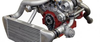
Today, the injection (or, scientifically speaking, injection) engine has almost completely replaced outdated carburetor engines. An injection engine significantly improves the vehicle's performance and power performance (acceleration dynamics, environmental performance, fuel consumption).
Fuel injection systems have the following main advantages over carburetor systems:
- Precise fuel dosing and, therefore, more economical fuel consumption;
- Reducing exhaust toxicity. Achieved through optimal fuel-air mixture and the use of exhaust gas parameter sensors;
- An increase in engine power by approximately 7-10% due to improved cylinder filling, optimal setting of the ignition timing corresponding to the engine operating mode;
- Improving the dynamic properties of the car. The injection system immediately responds to any load changes, adjusting the parameters of the fuel-air mixture;
- Easy to start regardless of weather conditions.
Incoming air condition control device
The air condition for the mixture is monitored by two devices:
- MAP Sensor – measures the volume of incoming air. It works on the principle - the more air enters when the damper is open, the more fuel is supplied. The goal is to create an optimal mixture ratio of 14.7:1.
- MAF Sensor - controls the mass of air that enters the cylinders. Structurally, it consists of a resistor and a platinum filament, the temperature values of which are ideally maintained at the same level. The ECU detects the temperature difference and sends a signal to the controller corresponding to a certain air flow.
You can find out which of these sensors is faulty using a car scanner. Some cars are equipped with a self-diagnosis mode, but you should not completely rely on its capabilities. Therefore, experts recommend using a scanning device and checking the characteristics of not only the sensors, but also the injection system.
Types of injection systems
The first injectors that began to be widely used on gasoline engines were still mechanical, but they had already begun to have some electrical elements that contributed to better engine performance.
A modern injection system includes a large number of electronic elements, and the entire operation of the system is controlled by a controller, also known as an electronic control unit.
In total, there are 3 types of injection systems, differing in the type of fuel supply:
- Central;
- Distributed;
- Direct.
Central (mono-injection) injection system
The central injection system is now obsolete. Its essence is that fuel is injected in one place - at the entrance to the intake manifold, where it is mixed with air and distributed among the cylinders. In this case, its operation is very similar to a carburetor, with the only difference being that the fuel is supplied under pressure. This ensures its atomization and better mixing with air. But a number of factors could affect the uniform filling of the cylinders.
The central system was distinguished by its simplicity of design and quick response to changes in the operating parameters of the power plant. But it could not fully perform its functions. Due to the difference in filling the cylinders, it was not possible to achieve the required combustion of fuel in the cylinders.
Distributed (multi-injection) injection system
The distributed system is currently the most optimal and is used on many cars. With this injector, fuel is supplied separately to each cylinder, although it is also injected into the intake manifold. To ensure separate supply, the elements that supply fuel are installed next to the cylinder head, and gasoline is supplied to the valve operating area.
Thanks to this design, it is possible to achieve compliance with the proportions of the air-fuel mixture to ensure the desired combustion. Cars with such a system are more economical, but at the same time the power output is greater, and they pollute the environment less.
Disadvantages of a distributed system include a more complex design and sensitivity to fuel quality.
Direct injection system
The direct injection system is a type of distributed injection and is currently the most advanced. It differs in that the fuel is injected directly into the cylinders, where it is mixed with air. This system is very similar in operating principle to a diesel one. It allows you to further reduce gasoline consumption and provides greater power output, but it is very complex in design and very demanding on the quality of gasoline.
Types of electronic injectors
There is a classification of electronic injectors based on the method of fuel injection. There are three types:
- Electromagnetic. Often typical for gasoline internal combustion engines (and with direct injection too). The design cannot be called very complex, and its main components are a valve with a needle (electromagnetic) and a nozzle. The operation of the specified injector is controlled by the computer, which provides voltage to the valve winding at the most suitable moment.
- Electrohydraulic. Mostly used on diesel engines. It is an electromagnetic valve complemented by a control chamber, as well as drain and intake throttles. The working principle of this type of injector is based on the participation of the pressure of the fuel mixture itself at any moment of operation. The activity of the electrohydraulic injector is monitored by the ECU, which sends operating signals to the solenoid valve.
- Piezoelectric. It is considered the most successful device among all those presented, but can only work on diesel units with a Common Rail injection system. The main advantage of this type is the speed of response, which guarantees multiple fuel supplies in one full cycle. The operation of the piezoelement is based on the hydraulic principle of operation (as in the previous version), which provides for the activation of the pusher piston by increasing the length of the piezoelement under the influence of an electrical signal from the ECU. The amount of fuel supplied at one time is determined by the duration of such exposure and the pressure of the fuel mixture in the fuel rail.
Source