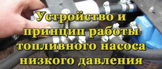
Hydraulic pump problems
One of the reasons for overheating of the car’s power unit may be a malfunction of the cooling system pump.
Most often the problem is that the hydraulic pump drive belt has broken or its tension is too weak. In this case, the pump will stop pumping antifreeze, or will not do it fully. Checking this is quite simple, you just need to bring in the engine and observe the behavior of the drive belt. If it works with slippage, the tension should be increased or the belt should be completely replaced with a new one. Most often this solves the problem. Situations arise when the problem lies in the pump itself: wear of the impeller, bearing, and sometimes even a crack in the shaft. Among other things, the joints connecting the pipes to the pump may not be sealed, and the pressure created by the pump will cause a coolant leak. Diagnosing a leak is quite simple; you need to place sheets of white paper on the floor under the engine for several hours. If even small spots of blue or greenish color are visible on it, this indicates wear on the pump gaskets.
You can check the functionality of the pump itself by holding the upper radiator hose with your fingers for a few seconds while the unit is running. A working pump will create strong pressure and after releasing the hose, you will feel as if the liquid is quickly running along the line. It is also worth remembering that increased noise of the internal combustion engine and play in the pump pulley indicate bearing wear. Usually its wear is associated with fluid seeping through the seal, which washes the lubricant from the bearing.
Water pump design for engine cooling system
The coolant pump, unlike the thermostat, can be partially replaced, but often car owners prefer to completely change the mechanism.
Pump replacement:
First of all, it is necessary to disconnect the vehicle mass from the battery, and the piston of the first cylinder must be at top dead center
Dismantle the belt tension roller and remove the camshaft pulley. Next, you should drain the coolant from the bottom plug in the radiator. After unscrewing the pump's mounting bolts, it must be disconnected from the cylinder block. By visually assessing the removed mechanism, it is important to determine its wear. If the impeller, oil seal and drive gear are damaged, it is better to replace the pump completely. The new mechanism must be installed with a new gasket, since the old one may have even minor damage, which will subsequently lead to a coolant leak.
The pump is installed so that the number indicated on the body faces up. Further assembly is carried out in the reverse order of disassembly. It is better to fill in new coolant, but you can also use the existing one if its resource has not yet been exhausted.
Circles of circulation
Installation and installation of the oil pump VAZ 2108-2109-21099
The cooling system in the car has two circulation circles: large and small. The small one is considered the main one, since when the unit is started, coolant immediately begins to circulate through it. In the operation of the small circle, only the channels of the cylinder block, the pump, and the interior heating radiator are involved. Circulation takes place in a small circle until the internal combustion engine reaches normal operating temperature, after which the thermostat activates and opens the large circle. Thanks to this system, engine warm-up is significantly reduced, and in winter, the system does not so much cool the unit as maintain its normal temperature regime.
Small and large coolant circulation circles
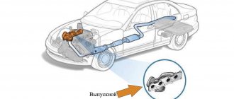
The operation of the large circle involves a fan, a cooling radiator, inlet and outlet channels, a thermostat, an expansion barrel, as well as those elements that take part in the functioning of the small circle. The outer circle, also known as the large circle, begins to work when the coolant temperature reaches 80-90°C and ensures its cooling.
How does a water pump work?
Cooling system liquid pump repair
The purpose of pumping equipment is to deliver liquid to the point of water collection. Regardless of the design features, the principle of operation of the water pump is the same. When the electric motor is turned on, a vacuum is created in the working chamber. Low pressure inside the housing promotes the suction of water, which moves to the outlet pipe. The outlet pressure has a force sufficient to overcome the hydraulic resistance of the pipeline.
Diagram of water movement in a vortex pump
The type of unit and the design of the working body determine the features of its operation.
Centrifugal pump
Centrifugal-type units are characterized by a combination of high performance and pressure. Optimal performance characteristics ensured their popularity among consumers. What does a centrifugal water pump consist of:
- body made of durable material - steel, brass, bronze, cast iron;
- a rotor rotated by an electric motor;
- impeller with blades (impeller);
- branch pipes – inlet and pressure.
Centrifugal pump device
The rotating blades of the impeller create centrifugal force inside the housing. The liquid is drawn in, pressed against the walls of the chamber, and then pushed out into the pipeline under pressure. The universal type of equipment is distinguished by a wide variety of models. The units are classified:
- by installation method - submersible, semi-submersible and surface;
- in the direction of the shaft - horizontal and vertical;
- by the number of impellers (stages) - single-stage, multi-stage.
Advantages of centrifugal type devices:
- Operates at temperatures up to +350.
- Durability and long service life.
- High efficiency.
- Affordable price.
For organizing water supply and irrigation, console-type models are recommended. They are designed for pumping liquids with impurities. Multi-stage installations will ensure high productivity and uninterrupted water supply. Cantilever structures require protection from external influences, so they are placed indoors.
Vortex pumps
Thanks to its design features, the equipment is capable of creating powerful pressure. How does a vortex type water pump work? When rotating, the impeller blades form a vortex of the pumped liquid. This property makes it possible to provide high pressure with small installation dimensions. Compact models are used for irrigating gardens and vegetable gardens. They are not sensitive to air bubbles entering the liquid, but quickly fail when mechanical impurities enter the water.
Vortex mechanism
Advantages of vortex units:
- Compact size.
- High pressure, installation pressure exceeds that of centrifugal models by 3-5 times.
- The simplicity of the design facilitates maintenance and repair.
- The equipment is capable of self-priming liquid.
Disadvantages include low efficiency (about 45%) and sensitivity to abrasive particles.
Vibration pumps
Vibrating-type units are used to organize irrigation and water supply of private farms and cottages from an individual source. The equipment is unpretentious in operation and can be used when pumping contaminated liquids. The operation of the device is associated with the influence of a magnetic field on a coil with a core. The metal core is connected to a flexible diaphragm which, when flexed, creates low pressure in the suction chamber. The liquid enters the housing, and when the core and diaphragm return to their initial position, it is pushed out through the outlet pipe.
Vibration units
Advantages of vibration units:
- The ability to pump contaminated water, which is used when pumping wells and boreholes.
- Affordable cost of equipment.
- The absence of rubbing parts increases the service life.
Vibration pumps are not without their disadvantages:
- Sensitivity to voltage changes.
- Destructive effects of vibration on well walls.
The choice of pump should be approached responsibly, taking into account its reliability and consumer characteristics. The main criteria for choosing equipment: pressure, productivity, sensitivity to contamination and power consumption. The unit should be purchased taking into account the operating conditions and purpose, then it will last the maximum period.
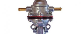
Water pump device
The cooling system pump has a fairly simple design with a minimum of parts: on a shaft mounted on two bearings there is a metal or plastic impeller that pumps antifreeze in a circle. To seal the connection between the shaft and the working chamber, an oil seal is used, and gaskets made of special rubber are used to seal the joints of the pipes. The entire structure is enclosed in a durable metal case made of aluminum or cast iron, resistant to vibration and temperature changes.
The pump shaft is driven by the engine crankshaft through a pulley, that is, mechanically. Thus, the water pump begins to work simultaneously with the engine, and the higher the vehicle speed (the higher the shaft speed), the more active the antifreeze moves in the system.
The pump is installed on the engine housing on a special gasket that dampens vibration during operation of the mechanisms.
The weak points of the water pump can be considered parts that are subject to friction and stress: the oil seal and bearings. As a rule, pump failure is associated with them.
Most often, the oil seal fails: due to its wear, coolant enters the bearings and washes away the lubricant from them, after which they become unusable.
Schematic diagram of the mechanical seal: 1. Rotating ring. 2. Stationary ring. 3. Sealing collar. 4. Pressure spring.
The spring in the oil seal performs an adjustment function: thanks to it, the friction rings are pressed tightly against each other, regardless of the degree of wear.
The service life of the water pump ranges from 60 to 160 thousand km (and in some cases more), and failure is due to mechanical wear.
There is no regulation for replacing the pump, but most often it is changed simultaneously with every second timing belt replacement, and at the same time a preventive check of the alternator belts is done.
As a rule, the water pump is not repaired: the fit of the parts is so precise that disassembly and reassembly are technically impractical. Therefore, in the event of a breakdown, it is easier and faster to install a new pump than to make labor-intensive and unreliable repairs.
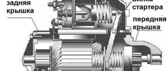
Pump Auto mechanic's dictionary
Volkswagen Passat 1.9 tdi Logbook restoration of the Water pump
A pump, also known as a car engine water pump, is a pump that creates forced circulation of coolant in the engine cooling system. The water pump is intended to organize the circulation of antifreeze or other composition in the cooling system. A malfunction of the pump leads to a serious disruption of the internal thermal regime of the engine, which is why it “boils” quite quickly.
This cannot be allowed to happen, so to make sure that the engine pump is working, you need to periodically listen and inspect the motor in order to repair or replace the failed unit in time.
Water pump design
The pump design in most cars is very similar, especially for domestic cars. And you won’t have to search for long to find where the pump is located either, since it is driven by the timing belt and is located near the radiator.
Structurally, the pump looks like this: a shaft is mounted in the cover. An impeller is mounted on it, the movement of which initiates the movement of liquid in the system. A drive pulley is mounted on the other side of the shaft, and in some car models there is also a fan. Through the timing belt and drive pulley, the rotational energy of the engine is transmitted to the shaft, the shaft drives the impeller and the entire system operates.
Pump device.
An oil seal is mounted between the housing and the impeller, the wear of which is associated with many pump problems. If this seal is bad, antifreeze or antifreeze gradually seeps into the cavity towards the bearings, washing away their lubricant. Because of this, the bearings begin to work much louder and wear out quickly, which leads to the pump jamming.
Causes and consequences of water pump failure
Since the car pump is a fairly simple mechanism, it does not break down too often, especially with normal engine care. However, even the most reliable pump can fail. There may be several reasons for the breakdown, including:
- wear of device components, including aging of the oil seal;
- initially low quality pump;
- unprofessional repairs.
If the system remains sealed, but the pump does not initiate fluid circulation through it, this will lead to an increase in engine temperature, as indicated by the gauge on the dashboard. Driving for a short time in this mode will cause the radiator to boil or the engine to seize.
If a pump leak occurs, you need to take action to eliminate it as quickly as possible.
Another sign of a pump failure is an antifreeze leak in the area where it is installed. If the leak is not very severe, this is not so scary, since the liquid circulating in the system will still perform its functions normally, it just needs to be topped up regularly. But still, if such a breakdown is detected, it is best to eliminate it immediately, because leaks tend to increase in intensively used engines.
Common water pump failures
There are not very many types of failures due to which a water pump can fail, which is due to the relative simplicity of its design. The most common are:
Problems with the impeller are the most common, but wedge bearings also happen.
impeller failure; deterioration of fastening of the impeller to the shaft; bearing jamming; deterioration of joint tightness due to engine vibrations, leading to coolant leakage.
Water pump repair
The engine pump is a repairable, dismountable unit. Here it is possible to replace both the entire mechanism and its individual elements, such as bearings. The fact that a car pump does not have to be completely replaced is good news, since this can significantly reduce the cost of repairs. True, access to this unit for partial or complete disassembly can be difficult. So, in some car models, this requires partially unscrewing the engine mounts, working from below from the inspection hole. Very often, the pump is replaced every second time the timing belt/chain is replaced, but if symptoms of a malfunction occur, the water pump is replaced even earlier, it all depends on the quality of the part and the level of work performed during the previous change of the timing drive and the part itself.
Related terms
Design of piston pumps and principle of operation
The very first hydraulic machines that converted the mechanical energy of piston movement into mechanical energy of a liquid and were known even before our era were piston pumps. Having undergone various additions, the principle of their operation has not changed since then.
In a piston pump, due to a cyclic change in volume, the cylinders are cyclically filled with liquid and then displaced.
The simplest example of the operation of any modern piston pump can be the working cycle of a simple single-stage hydraulic machine, consisting of a cylindrical working chamber with two pressure and suction holes and a piston performing reciprocating movements inside it. To convert rotational motion into reciprocating motion, the design provides a crank mechanism.
Liquid suction in such a device occurs due to the creation of low pressure in the working chamber while the piston moves to the right with the discharge valve closed, and the pressure of the pumped liquid opens the suction valve and the working chamber is completely filled.
Then, during the return movement of the piston, excess pressure is created in the cylinder, much greater than in the discharge pipe. The suction valve closes, and the discharge valve opens for supply, due to which the process of pumping or displacing a liquid equal to the volume of the working chamber into the pressure manifold of the pipeline occurs.
The useful volume of the working chamber is the difference between its maximum and minimum volumes, determined by the position of the piston.
The continuity of supply of working fluid depends on the frequency of movement of the piston. To ensure that the pressure inside the pressure pipeline is stable, double-acting hydraulic units with several working chambers are usually used; more precisely, the cylinders in them are divided into two equal parts, each of which has suction and pressure pipes equipped with valves. This design allows different parts to have different pressures. While in one part, under the action of the movement of the piston, the suction process occurs, in the other, injection occurs and vice versa. To combat pulsation, air caps and hydraulic accumulators are used.
Single-acting piston pumps include plunger pump, slider pump, and diaphragm pump. The diaphragm differs from the plunger only in the presence of a special active or passive diaphragm in its working chamber. Active diaphragms, transmitting force to the liquid from the rod, are under high pressure and therefore, due to their low fatigue strength, are used in low-pressure piston pumps with a large number of swings. But passive diaphragms only separate the liquid that transfers energy from the plunger to the pumped liquid and therefore they are used in pumps with high pressures with a small number of swings.
Double-acting piston pumps have a more complex design, providing a more uniform supply of the pumped liquid due to the presence of two or more working chambers. Each chamber operates as a single-action pump, and in the so-called differential pumps in the right working chamber, used as an auxiliary one, there are no valves, but due to its presence, the fluid supply does not depend on the movements of the piston.
The ability to regulate pressure pressure by varying the frequency ranges of the piston stroke, small dimensions and interchangeability of component parts are the main advantages of piston pumps.
The disadvantages include the impossibility, due to high inlet pressure, of sequentially connecting several piston pumps into one circuit, the inability to pump liquid media with abrasive particles, the need for an additional cooling system and an additional seal between the piston and the cylinder walls of the working chambers. And also, unlike other positive displacement pumps, piston pumps are not reversible due to the presence of valves, since they cannot operate in hydraulic motor mode.
Vibration pump device
The vibration pump consists of the following parts:
- eye for cable;
- power cable;
- suction port;
- pipe branch;
- valve;
- piston;
- stock;
- emphasis;
- diaphragm;
- coupling;
- pump housing;
- shock absorber;
- anchor;
- frame;
- potting compound;
- coil;
- core.
Fig.3
Vibration pumps \Fig. 3\ are also called electromagnetic. When current flows through the coil winding, an electromagnetic field is formed.
Under the influence of an electromagnetic field, a core connected to a rubber diaphragm is retracted. With the reciprocating movement of the rubber diaphragm, a constant flow of water is created in the device.
The design of this type of pump is simple in design. If there is any overload, the core winding may fail. Repairing such pumps seems to be simplified and does not require much knowledge in electrical engineering.
Fig.4
The vibration pump consists of electrical \Fig. 4\ and mechanical parts. An alternating magnetic field arises in the gap of the electromagnet, which sets the lever in motion. The lever is connected to the bellows \S\, the bellows, pulsating, pumps liquid through the valves \k\.
Vibration\electromagnetic\submersible electric pump
Operating principle of a centrifugal pump
The centrifugal force of water in such pumps is created by the rotation of the impeller blades. The pump performance will accordingly depend on the rotation speed of the electric motor rotor. That is, pressure energy is created here, a stream of water under pressure is pushed into the pipeline.
Fig.5
The electrical circuit of the centrifugal pump \Fig. 5\ consists of:
- capacitor;
- cord\network cable\;
- starting and operating stator windings
- thermal\current\ relay.
Submersible centrifugal pump, caliber NPC
Liquid pump
Purpose and design of the coolant pump
The liquid pump, or pump as it is called, creates forced circulation of liquid in the cooling system. As a rule, single-stage centrifugal pumps are used in engine cooling systems. The liquid pump is usually driven from the crankshaft using a V-belt, toothed belt or spur gear.
The liquid pump consists of a housing, which is a volute, a drive shaft placed in the housing on bearings, an impeller, which is often integral with the drive shaft, as well as sealing elements - cuffs, seals, etc.
The bearings on which the drive shaft with the impeller is mounted most often do not require periodic lubrication - they are closed or sealed, and are pre-filled with refractory grease. Sometimes bearings are lubricated with coolant - antifreeze.
Figure 1 shows the liquid pump and fan of the ZIL-431410 engine, which consists of a housing 7, an impeller 5 and a bearing housing 10, interconnected through a gasket 6. The pump shaft 4 rotates in two ball bearings 3, equipped with sealing collars to retain oil. The front bearing is fixed by a thrust ring 2, and the rear bearing is kept from moving by a spacer sleeve 11.
Impeller 5 is attached to the end of the shaft. When the impeller rotates, the coolant from the supply pipe 9 flows to its center, is captured by the blades and, under the action of centrifugal force, is thrown towards the walls of the housing 7, moves in a spiral along the walls and is fed into the cooling jacket through hollow outlets 8.
The tightness of the rotating parts located in the pump housing 7 is ensured by a self-clamping sealing cuff installed in the impeller and consisting of a sealing washer 17, a rubber cuff 16 and a spring that presses the washer 17 to the end of the bearing housing. With its protrusions, the washer 17 fits into the grooves of the impeller 5 and is secured with a holder 18. At the front end of the shaft 4, using a sleeve 12, a hub 13 is installed, to which the pump and fan drive pulley 14 is attached.
In Fig. Figure 2 shows a longitudinal section of the liquid pump of the VAZ engine cooling system. As can be seen from the figure, the design differs little in principle from that discussed above.
***
Academic disciplines
- Engineering graphics
- MDK.01.01. "Car design"
- General structure of the car
- car engine
- Car transmission
- Steering
- Brake system
- Suspension
- Wheels
- Body
- Car electrical equipment
- Basic car theory
- Basics of technical diagnostics
- Fundamentals of hydraulics and heat engineering
- Metrology and standardization
- Agreecultural machines. Agreecultural equipment
- Basics of agronomy
- Transportation of dangerous goods
- Materials Science
- Management
- Technical mechanics
- Tips for graduate student
Olympics and tests
- "Engineering graphics"
- "Technical Mechanics"
- "Engine and its systems"
- "Car chassis"
- "Car electrical equipment"
Centrifugal pump - universal equipment
Devices of this type are used in almost all areas - both industrial and household. The operating principle is based on the creation of centrifugal force inside the body, due to which water moves and pressure is created. The blades and wheels of the working part, rotating, draw in the liquid, press it against the wall, and then push it out into the outlet hole. Depending on the design and purpose, devices are divided into many groups. They can be surface and submersible, cantilever, horizontal, vertical, monoblock, single- and multi-stage.
All structural elements are made of high-strength materials, the parts practically do not wear out. The pumps are expected to run continuously. Therefore, they are designed to be easy and fast to service. The devices can operate at high temperatures and in chemically aggressive environments; the characteristics depend on the features of the specific model. Some of them can withstand up to 350 degrees.
The advantages of centrifugal pumps include reliability, durability, reliability, reasonable price, the ability to be equipped with the necessary automation, and high efficiency. However, like any other device, pumps of this type have their own disadvantages. So, to start the device, the housing must be filled with water, since due to the low centrifugal force, water is not sucked into the pipe. If air enters the inlet pipe, the pump may stop. In addition, if the resistance in the electrical network changes, this may affect the stability of the device.
Surface centrifugal pumps are mobile, easy to dismantle and transport, but are poorly suited for stationary installation
Centrifugal cantilever pumps are widely used. They are used for pumping clean and dirty water containing impurities and small solid particles. For water supply systems of houses and cottages, single-stage horizontal cantilever pumps are used. Multistage horizontal pumps are a design that operates as several identical, series-connected, single-stage devices. Thanks to this, they are able to provide powerful pressure in the system.
Centrifugal water pumps are purchased for homes, cottages, watering and irrigation systems. They are installed in water supply systems powered by wells. Submersible and semi-submersible models are used. The former are easier to install, and the latter are easier to maintain. To install a semi-submersible model in a well, special conditions are required. This is labor-intensive work, therefore, despite the obvious advantages, owners of private houses often opt for submersible models. They can be installed in wells where there were deviations from the vertical when installing the casing. The disadvantages of the structures include high sensitivity to sand and dirt.
We offer an overview of centrifugal monoblock water pumps that are perfect for the garden:
Latest entries In September, you can plant 8 varieties of currants that are resistant to powdery mildew10 beautiful flowers grow well in sandy soil and are not capricious7 common mistakes that prevent you from growing many eggplants
Liquid pump
Multipliers or booster compressors are sometimes used as liquid pumps, for example, the ultra-high pressure compressor of the High Pressure Institute (Fig. 65) works well at a pressure of 5000 atm and, as a liquid pump, with a capacity of up to 60 l/hour. Although the amount of harmful space in this compressor is very small (5 - 6%), its performance nevertheless increases when working on liquids that are less compressed than gases.
If you have a liquid pump or multiplier, it is more advisable to replace the bomb / with them, the cooling and heating of which (even one-time) requires time and coolant consumption. If a mercury seal is installed in front of the reactor / / (Fig. 89), and the reactor itself and part of the seal are filled with gas from a cylinder or compressor, then experiments with gases can be carried out at the installation.
When the liquid pump operates, oxygen or nitrogen leaks (through the gap between the plunger and the cylinder liner), which returns back to the column, passing along the way through a filter 15 made of porous metal to remove graphite particles.
| Hydrodynamic emitter UGI-D. |
Liquid pumps are the most commonly used.
Note that piston liquid pumps allow suction of gas with the same success as a compressor.
Unlike liquid pumps, air and other gas compressors (except low pressure compressors) are cooled by water or other means (surface cooling) to remove the heat that the compressor generates.
| Cycle diagram of the operation of a zeolite drying and cleaning unit in normal mode. |
O-2, the liquid pump jacket and the annulus of the main heat exchanger are supplied to valve 3 - 9 (nitrogen discharge valve 3 - 3 is closed); Then the air is directed to the heater of the cleaning unit and to the regeneration line.
The work required to drive a liquid pump is so insignificant that it can be ignored.
In some cases, liquid pumps are used to create gas pressure. They are used when working with ultra-high pressures, as well as at lower pressures.
In installations with liquid pumps that supply the resulting product into cylinders or a pipeline under pressure, gas tanks are not needed.
For what purpose are liquid pumps used?
If liquid pumps fail, it is necessary to reduce the temperature in the columns to 360 C, maintaining gas circulation.
If liquid pumps fail, it is necessary to reduce the temperature in the columns to 360, maintaining gas circulation.
Working principle of a water pump
The main component of the water pump, which carries out the main work, is the rotor or impeller (impeller). Typically, the rotor is made of steel, copper or cast iron. It consists of two disks connected to each other. Between them are curved blades running from the center to the edges. The bend is directed against the axis of rotation of the wheel itself. In the center of the wheel there is a neck (hole), the diameter of which is equal to the diameter of the pipe through which water or any other liquid is sucked in. The pipe and the wheel have a tight connection so that the blades have contact with the incoming water. The rotor blades are located so as to prevent fluid from flowing into the cracks, and there was only free space in the disc grooves.
There are several types of rotors:
- Open (open blades located on one disk);
- Closed;
- Stamped;
- riveted;
- Cast.
You don't need any special skills to use a water pump.
An open type rotor differs from a closed type in that the blades are placed on one disk and do not have a covering. Open type rotors are used for pumping very thick liquids and suspensions at low pressure, because These blades are easy to clean. A closed-type rotor, made of one monolithic part, is often installed in simple pumps. Stamped rotors are installed in large and powerful pumps.
Design and principle of operation of a piston pump
Piston-based water pumps are used when a larger type of liquid pump or high-pressure pumps are not cost-effective to use in a small area.
It can be used in an autonomous water supply system from a well, or you can use a manual version. A manual piston pump is used if there is no light in the country or the water consumption is not too large or for a plant sprayer.
Manual piston pump device
It consists of the following elements:
- cylindrical body;
- stock;
- piston;
- inlet pipe;
- valve in the bottom cover of the device;
- outlet pipe.
The piston is located inside a cylindrical body. In the top cover of the housing there is a hole (flange) with a special rubber gasket. A rod passes through the hole, one edge of which is welded to the piston. The rubber gasket is responsible for the tightness of the cylinder and maintains high pressure in it.
Work cycle
The piston has a check valve. It lets water in but prevents it from coming out. Exactly the same valve is located inside the inlet tube in the lower cylinder cover. When the rod rises up, it pulls the piston along with it. In this case, an area of discharged pressure is formed in the sub-piston space, into which water is sucked through the bottom valve. Then the piston begins to move downward, creating pressure on the lower valve. It closes and water is forced through the top valve into the space above the piston.
The second cycle of upward movement of the piston forces the liquid into the outlet tube. From there it enters the water supply system and moves to the tap, after which the entire work cycle is repeated again. The inlet tube of the device is usually made of rigid materials, since it should not stick together under the influence of retracting force. For this purpose, a reinforced hose or plastic pipeline is used.
A high-pressure liquid piston pump, unlike deep-well devices, is installed above the entrance to a well or well. And suction occurs through a long hose. In this case, the rod is fixed to the hydraulic motor if the model is an electric pump, or to a metal rocker arm if a manual water pump was purchased.
The valves of the device are usually either a ball or a membrane in a diaphragm piston type pump. In the first case, a ball made of glass, hard plastic or hard rubber is used as a flap for a conical hole. The peculiarity of the membrane type is that a rubber plate fixed on one side is used as a flap.
Cam rotary piston pump
The maximum depth from which a piston pump with this design draws water does not exceed 8 meters. If the water surface is lower relative to the location of the device, atmospheric pressure will prevent injection. There are models for deep reservoirs, but their design is different. Their duralumin rod does not enter through a flange, but through an outlet tube on the top cover. This device increases the pressure in the cylinder and lifts water from a depth of up to 30 meters. The device operates when immersed in water depth of 1.5 m.
Double acting pumps
The main reason why the double-acting piston pump was developed and began to be actively used is the desire of manufacturers to reduce the level of pulsation in the flow of liquid pumped into the pipeline system. In order to understand the advantages of using a double-action pumping device, it is enough to understand how this type of piston liquid pump works.
A special feature of the double-action liquid piston pump design is that the rod and piston cavities of this machine are equipped with individual valve systems. This design of a double-action piston pump, the uniqueness of which can be seen even from the photo, allows not only to eliminate flow pulsations in the pipeline system, but also to significantly increase the efficiency of using the machine itself. Meanwhile, single-acting piston pumps, when compared with double-acting models, due to their simple design, are more reliable and durable.
Operating principle of a double-sided piston pump
There is another design scheme for a piston pump, which can be used to eliminate pulsation processes in pipeline systems. Pumping equipment made according to this scheme involves the use of a special hydraulic accumulator. The main purpose of such hydraulic accumulators used to equip pumping stations is to accumulate the energy of the fluid flow at moments of peak pressure in the pipeline and release it when such pressure is not enough for normal operation of the system.
However, no matter what types of piston pumps are used and no matter what additional technical devices the pumping stations are equipped with, it is not always possible to eliminate pulsation processes in pipelines. In such situations, additional equipment is often used to ensure effective removal of excess liquid outside the pumping station.
Electric Cooling Liquid Pump
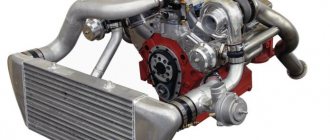
A promising direction in the development of the cooling system is the use of electric liquid pumps. The cooling system of modern engines also uses electrically controlled double thermostats. The use of an electric pump compared to a conventional mechanical one and electrically controlled thermostats makes it possible to achieve better compliance with internal pressure and reduce losses due to the movement of coolant flows. The electric pump allows you to provide the required coolant flows without depending on the crankshaft speed, which is typical for mechanical pumps.
Rice. Electric liquid pump: 1 – impeller; 2 – electric motor with a stator protected from liquid influence; 3 – electronic executive system
The electric pump and electrically controlled thermostats are controlled by the engine control unit, the memory of the parametric characteristics of which contains data on the heating and cooling temperatures of the engine. The control unit receives information from transmission, engine, etc. sensors and provides information to actuators for the operation of electric pumps, electrically controlled thermostats, electric fans and controlled air dampers to regulate air flows. The pump shaft rotation speed varies over a wider range than in mechanical pumps, for example, the minimum rotation speed is 18 rpm. Electronic control allows the engine and oil to warm up quickly, which reduces friction and reduces fuel consumption.
Electric pump cooling systems use different coolant circuits, allowing fluid to circulate in large or small circuits depending on load and engine speed. This circulation system is more efficient than a conventional one and reduces energy consumption to drive an electric liquid pump, the power of which does not exceed 200 W.
Electric pumps can also be used as additional pumps to the main pump. When the engine stops running, coolant circulation also stops, which can lead to localized overheating of the cylinder head. This can be avoided by an additional electric coolant pump, which, if the temperature is too high, circulates a certain part of the coolant after the engine is turned off. The additional electric pump only works when the engine is switched off. When a certain temperature is reached, the additional electric coolant pump is switched on. At the same time as the additional pump, the engine cooling fan also turns on.