Replacing crankshaft bearings
Crankshaft bearings are semicircular plates made of steel or aluminum, and have a great influence on the proper operation of the plain bearings.
It is necessary to change the crankshaft liners in case of their physical wear, which inevitably occurs due to their abrasion and an increase in the gap between the crankpins and the liners. If the gap in the indicated location increases, the crankshaft begins to move too freely, and therefore the oil pressure drops. This leads to engine malfunction.
Sometimes replacing crankshaft liners is done not due to natural wear, but because of necessity. A sign that the liners are faulty is when they rotate due to sticking to the crankshaft journal. In such a situation, engine operation is impossible. Watch the video “Replacing crankshaft bearings on a Ford Transit” below
Rotation of the liners can occur for several reasons:
- no lubrication;
- the lubricant does not have the optimal consistency (either too thin or too thick);
- abrasive particles have entered the lubricant;
- The bearing caps are installed without the required tension.
Crankshaft grinding
The crankshaft grinding procedure always precedes the installation of new crankshaft bearings, unless the crankshaft has been replaced. The point of grinding is to fit all the necks to a certain size of the liners. What size is decided by the master.
The VAZ crankshaft can be ground no more than 4 times, and the GAZ and UAZ crankshaft can be ground no more than 6 times. Accordingly, VAZ crankshaft liners come in 4 sizes: 0.25 mm, 0.50 mm, 0.75 mm and 1.0 mm. After the first grinding, the minimum size of the liners is set, after each subsequent grinding, the next size of the liners is set in order. Sometimes, in case of severe wear of the neck, liners may not be required in the next size, but immediately 2 sizes larger. Only a specialist can solve this.
GAZ and UAZ crankshaft liners have 6 repair sizes. In addition to those listed, another 1.25 mm and 1.50 mm are added. These engines can do 6 grinds.
The process of replacing crankshaft bearings
For this procedure, you will need to completely disassemble the engine, so doing this will be justified and feasible only if you have sufficient experience in the field of repairs, as well as specialized equipment. In other words, this needs to be done at a car service center, and our description is provided to familiarize you with the process.
- Remove the hood and battery;
- Drain the antifreeze;
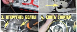
- Disconnect from the engine and remove: pumps - fuel and cooling systems, distributor, generator, radiator, cylinder head, carburetor and starter;
- Disconnect and remove the clutch block;
- Place the engine on a workbench and disconnect from it: flywheel, pulley, camshaft drive cover, oil pump drive chain and gear, flywheel and rear cuff holder;
- After removing the oil pan, access to the crankshaft will open;
- Remove the caps of the connecting rods and main bearings of the crankshaft; when the bearing caps are removed, it immediately becomes clear where the bearings have turned;
- Remove the crankshaft and determine the condition of the journals;
- Grind the crankshaft;
- Replacement of liners with new ones.
Video: Replacing bearings and installing a crankshaft on a Ford Transit
How to change liners without removing the engine on a VAZ 2109?
Most not-so-informed car enthusiasts, when presenting their stories on forums, adhere to the point of view that replacing liners on an engine without removing it from the engine compartment is something out of science fiction. However, it is not! Replacing connecting rod bearings without removing the crankshaft is a typical repair procedure for shipwrights. Parts of marine engines have a significant mass and size, so removing a multi-ton power unit over and over again is not rational. But they have a technique that can be applied to ordinary cars.
Depending on the condition of the crankshaft journals, replacement of the liners is carried out both on site and after dismantling the power unit. To measure the gaps on an installed engine, you need to lift the crankshaft up. For diagnostics, as a rule, a micrometer is used, however, measurements can be taken, as they say, “by eye.” You should immediately evaluate the possibility of boring the crankshaft.
Without question, the liners are changed in the situation when they are turned over. How do you know this happened? Yes, the mechanism will begin to make a noticeable knock, and the power unit will constantly try to stall. There are also cases in which the crankshaft simply jams. When this happens, you will no longer be able to drive your car any further.
1. The first thing a car enthusiast who wants to deal with defective liners should worry about is a hole or overpass. This will help us gain easy access to the engine.
2. If any protection for the power unit is installed, dismantle it and drain the oil.
3. We remove the crankcase, oil supercharger and spark plugs. We disconnect the cover of the main bearing in which the liners need to be replaced.
4. We bridge the device for installing liners. If we don’t want to bother with this, we use an ordinary cotter pin, bending it in place.
5. We turn the crankshaft clockwise, oriented towards the front of the engine. With this maneuver, the liner will rotate along with the shaft, which will cause it to come out.
6. Lubricate the new product and place it on the side without the lock. The liner should fit with its smooth surface. We turn it into place and remove the mounting device.
7. Lubricate the new liner and insert it into the main bearing cover.
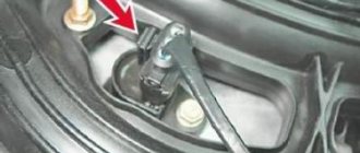
8. Adjust the cover into place. The arrow marked on it should be directed towards the front side of the power unit.
9. Tighten the cover bolts with a force of 50 Nm + (40–60).
10. Reassemble everything in reverse order.
The topic discusses the replacement of crankshaft liners without removing the engine and the shaft itself. However, the car enthusiast should also know that whatever the reason for replacing the liners, it is better to bore the shaft. So, experts say. Even if troubles occurred with only one neck, then all the rest will have to be adjusted to it.
When producing power units at the Volzhsky Automobile Plant, the manufacturer installs standard liners. For VAZ models, there are two pairs of repair types, and it follows that the shaft itself can be bored no more than four times.
As for purchasing inserts, they are sold in sets. This applies to all their varieties.
Source
How to make an insert in a work book
Tractor T-16 Design, principle of operation, characteristics and repair of tractors T-16, T-16 M and T-16 MG
As mentioned above, the insert is issued only if the main document is completed, and both sections on work can end, and information about awards.
That is, in such a situation, this aspect is not paramount; the liner is started accordingly, taking into account the rules stipulated in Resolution No. 225.
Issuance procedure
Each form of a labor book and its insert purchased by an enterprise is registered in a special journal; accordingly, when the form is issued to an employee, an entry is made in the specified journal, the form of which is approved by Resolution No. 69.
Although the employee himself can purchase the insert, this form will still be subject to registration in the journal.
Rules for registration and maintenance
Clause 38 of Resolution No. 225 states that the insert is maintained in accordance with the same rules that are established when maintaining a work book, but, nevertheless, taking into account some nuances, as well as the absence of separately developed rules, many questions arise when entering those other data .
Where to put a stamp indicating that the insert has been issued?
In particular, paragraph 39 of Resolution No. 225 establishes the rule for the mandatory insertion of a stamp on the establishment of the insert, but at the same time, the place of the stamp is not specified, and therefore, according to established practice, the mark on the establishment of the specified document is entered in the upper right corner of the title.
That is, in the absence of a stamp, it is quite acceptable to make a manual entry stating that the insert is issued, indicating the date of establishment, number and series of the specified document.
A sample insert record is as follows: Insert issued: Series. Number. Date of.
An illustrative example:
Title registration
The design of the title page of the insert is not much different from the same procedure when filling out a book about work.
Almost the same data is entered, namely:
- surname, name, patronymic of the employee;
- Date of Birth;
- education;
- speciality.
But, nevertheless, there are some differences.
That is, if there was a previous change of name, then the insert indicates new data, the same applies to newly acquired education, if available and specialization.
Example (filling sample):
Date of completion
After filling out the above-mentioned fields, the date of filling out the insert is indicated, which, accordingly, is also indicated as the real one, and not the one indicated in the work book.
That is, the date the insert was created will correspond to the date of the entry made for the first time in the insert.
Are stamps needed?
Accordingly, after entering the date, the personnel employee who fills out the insert must put his signature and also put the company’s seal, by analogy with filling out the main document - a work book, that is, there are no distinctive features in this aspect.
Numbering of entries
After filling out the title page, an entry is made, the numbering of which will not correspond to the number 1, taking into account the beginning of a new document, but quite the opposite, because the insert is a continuation of the work book, accordingly, the numbering continues from the next number, which was indicated in the work book.
How to sew?
As a rule, the liner is attached to the work book in several ways, since not everyone knows whether it needs to be sewn in, given that this rule is not established at the legislative level.
In particular, in some cases, it is commonplace to use a large paperclip for attachment or even store them together, although it is still recommended to sew in the insert, of course, after filling out this document.
This procedure should be carried out so that the insert does not get lost, because the paperclip may come off, and then confusion in the documents will be inevitable.
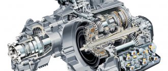
Difference between main and connecting rod bearings
Engine disassembly
You need to know that there are two types of liners. These are connecting rods and main ones. The first are located between the connecting rod and the crankshaft journal. The root element is similar to the first in its purpose. However, it is located where the crankshaft passes through the engine housing. The inserts vary in size. Dimensions depend on the type of internal combustion engine for which a specific part is manufactured. There are also special repair inserts. They are different from the original new ones installed in the engine. Repair inserts differ only in marks that are multiples of 0.25 mm. So, their sizes are approximately the following - 0.25 mm, 0.5 mm, 0.75 mm, 1 mm.
Liner - crankshaft
| Checking the diametrical clearance in the crankshaft bearing.| Diagram for replacing the upper main bearing shell.| Restoring worn parts by installing bushings. |
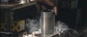
Communities Diesel Power Diesel internal combustion engines Blog Replacing main bearings without removing the crankshaft Lifehack
The crankshaft bearings can be replaced while the vehicle is in use, without removing the shaft. Replacement is carried out without any additional adjustment and only in pairs.
The crankshaft liners of carburetor engines allow one boring to the repair or nominal size on high-precision machines of the Odessa Machine Tool Plant. When this possibility has been exhausted, galvanic coatings are applied to the working surfaces of steel-aluminum liners made of AO-20-1 or AO-6 material.
| Checking the diametrical clearance c. |
Replacement of the crankshaft liners is carried out when the bearings are knocking and the pressure in the oil line drops below 0 5 kgf / cm2 at a crankshaft speed of 500 - 600 rpm and the oil pump and pressure reducing valves are working properly. The need to replace the liners is due to the diametrical clearance in the main and connecting rod bearings; if it is more than acceptable, the liners are replaced with new ones. The nominal clearance between the liners and the main journal should be 0 026 - 0 12 mm, between the liners and the crankpin 0 026 - 0 П mm, depending on the engine model.
| Scheme of installing an elastic DRM on the shaft journal. |
To avoid damage to the crankshaft liners when the engine is running, it is necessary to carefully remove burrs from the tape, maintain the angle between its petals, their length and the depth of the flats on the shaft journal.
It is known that the current trend in the production of crankshaft liners is the use of a third soft layer, which serves to speed up and improve running-in. For this purpose, for example, lead-tin alloys are used. Covered with microcavities, possessing high oil absorption and wearability, the self-alloying surface with a large actual contact area represents a kind of third layer. Its feature is high manufacturability and the absence of an interface with the main antifriction layer, which guarantees relatively higher fatigue strength regardless of the near-surface hardness formed during the factory running-in process.
Currently, lead bronze, SOS-6-6 alloy, etc. are used as the antifriction layer of crankshaft liners. These materials have greater strength, hardness and heat resistance than tin babbitts. Their disadvantage is their high tendency to corrosion, due to their high lead content. The composition and structure of the alloy largely determine its susceptibility to corrosion.
The frame is installed on the foundation, the crankshaft liners are placed on the wedges and alignment begins. First, the crankshaft axis is horizontal, checking it with a calibrated roller and a level (Fig. Next, the frame is aligned along the cylinder axis. The check is carried out with a level installed on the lower guide surface of the crosshead (Fig.
Modern high-performance engines place particularly high demands on the reliability of crankshaft liners. In this regard, Babbitt liners are unpromising; They are used mainly only on low-speed marine diesel engines with small loads on the crankshaft bearings.
The areas of use of aluminum bearing alloys in the Soviet Union are expanding every year. Crankshaft liners for a number of automobile engines are made from a strip with a layer of AO20-1 alloy. This strip is manufactured at the Zavolzhsky Motor Plant. In particular, positive results have been obtained from the use of such bearings in heavily loaded forced engines of ChTZ tractors.
The most favorable conditions for the formation of varnish are created in stagnant zones of surfaces, in particular in the grooves for rings and in areas of the side surface of the piston that have recesses; For these places, the presence of high temperature is not necessary. The formation of varnish was observed in the recesses made specifically on the antifriction layer of the crankshaft liners.
When the ambient temperature drops, the operation of diesel engines becomes much more difficult, since the viscosity of the oil increases greatly - it thickens and sometimes freezes. Oil thickens in the engine crankcase, oil filters, on the crankshaft journals and liners, in the gaps between the piston and the cylinder mirror and on other rubbing parts. This makes it difficult to start the engine, normal lubrication conditions are disrupted, and the wear of its parts sharply increases during the start-up period.
| Staggering and wear of the crankshaft main bearings. |
How to change main bearings without removing the engine
The pressure light is on, when you press the gas a little, it disappears. Congratulations, whoever tells you anything about the oil filter, the oil itself, the sensor, the oil pump, etc. is nonsense. I don’t know how it’s possible to fix the liners like this, I already got the car with this problem, and I was hammering x8, I thought that maybe it was the generator, and so I drove for about 9 months. The engine didn’t knock, it ran quietly, it drove. When I found out, I was very upset, I thought about removing the box and crankshaft, but as always, I don’t want to spend a lot of money. It was decided to do it without removing the crankshaft, without removing the fifth main liner.
And the one that stands on the yoke is quite easy.
There were no options, nothing was being done on the crankshaft, the condition of the crankshaft in my case is still acceptable, even if you have a line there for the entire journal, don’t worry, install new ones of the same size. I have STANDARD liners for connecting rods and main bearings, so you install standard ones.
Every detail is important for the smooth operation of a car engine. A special position in the crank mechanism system is occupied by the crankshaft liners. Thin semicircular steel-aluminum plates surrounding the main and connecting rod journals are the outer races of the plain bearings, and the overall performance of the engine depends on their condition.
When is it necessary to replace crankshaft bearings?
Under the conditions of the physical and thermal loads that the crankshaft has to endure, only plain bearings can keep it on the axis and ensure the operation of the crank mechanism. The main and connecting rod journals serve as internal races, and the liners, respectively, serve as external races. The engine block system has a network of oil lines through which engine oil is supplied to the liners under high pressure. It creates a thin oil film that reduces friction and allows the crankshaft to rotate.
Features of operation
During engine operation, the liners are subject to constant loads due to mutual friction of these parts. Therefore, the installation of the main bearings must be carried out with reliable fixation to avoid their displacement by the rotating crankshaft. To achieve this, measures are taken:
- Firstly, they take into account the characteristics of friction of the parts in question, which manifests itself when they slide against each other under load. Its value is determined by the friction coefficient and the magnitude of the load on the interacting parts. Therefore, to ensure reliable retention of the liners, the impact of the crankshaft on them should be reduced. For this purpose, the coefficient of friction is reduced by using antifriction materials that are applied to the surface of the liners.
- Secondly, the main liners are mechanically held in place. Two methods are used for this. These elements are installed with interference specified structurally. In addition, on each of them there is an additional element called a tendril, which also serves for holding.
You need to know the dimensional parameters in order to ensure proper interference and correctly install the main bearings. The dimensions of these elements are selected based on the diameter of the bed. According to this parameter, the liners are divided into size groups, the designation of which is contained in the marking.
Based on size, crankshaft main liners are divided into nominal and repair. There are four repair sizes with a difference of 0.25 mm. They are used if replacement is carried out for a ground crankshaft in accordance with its dimensions.
Why does the liners rotate?
The liners in the engine are installed in special installation locations (liner bed). Installation requires special fixation, since the liners have holes in their body, which allows engine oil to be supplied to them. The indicated holes must clearly coincide with the holes that are drilled in the parts themselves for the passage of lubricant. Also, fixing the liner is necessary taking into account the fact that during engine operation friction occurs on the surfaces of the mating elements.
Taking into account the above information, it becomes clear that if the connecting rod bearing has turned, the reason may be as follows:
- insufficient fixation of the liner;
- strong friction on the surface of the liner;
As is known, friction occurs as a result of the sliding of two bodies relative to each other in the presence of a certain load. The total magnitude of the friction force will depend on the magnitude of the load on the rubbing pair, as well as on the friction coefficient. In order to reduce the friction force in the manufacture of parts, special anti-friction materials are used that have a low coefficient of friction.
As for the liner, anti-friction material is applied to its surface. The crankshaft performs a rotational movement in relation to the liners; at the junction of the liner and the crankshaft, a friction force arises, which tends to rotate the liners in relation to their installation locations. To protect against rotation and displacement, the liner is held in place by a special tendril. Also, during installation, the liners themselves are inserted with a certain interference, the value of which is calculated by the designers of a particular internal combustion engine.
Causes of wear
As mentioned above, when the engine is running, each main liner of the engine is constantly exposed to a frictional force, tending to displace it from its original location. In the original state of a working engine, the strength of the parts is calculated with a margin in order to withstand such loads. For power units up to 200 hp. With. The stress on the liner ranges from 0.1 to 1 kgf. The magnitude of its force is proportional to the load at a constant coefficient of friction.
In addition, the main liners are protected by the fact that they operate in liquid friction mode. This is ensured by the use of oil, which creates a film between the shaft journal and the working surface of the liner. In this way, the parts in question are protected from direct contact and a minimum friction force is achieved. The formation of an oil film is determined by the speed of mutual movement of the rubbing parts. The best online casinos in Russia: Honest rating of TOP 10 casinos at the beginning of 2021. As it increases, the hydrodynamic friction regime increases. This term refers to an increase in the efficiency of pulling the film into the gap and an increase in its thickness as a result. However, as the speed of the parts increases, the amount of heat generated during friction also increases, and, consequently, the oil temperature increases. This leads to its liquefaction, resulting in a decrease in film thickness. Therefore, for optimal operation it is necessary to achieve a balance between the considered processes.
If the integrity of the oil film is damaged, the friction coefficient increases. As a result, the cranking torque generated by the crankshaft increases even under constant load.
However, sometimes the opposite situation occurs when increased loads for some reason lead to a decrease in the thickness of the oil film. Also, as a result of this, the temperature increases, especially in the friction zone. As a result, the lubricant dilutes, further reducing the thickness.
These processes can be interconnected and manifest together. That is, one of them may be a consequence of the other.
Therefore, the cranking torque is significantly influenced by the viscosity of the oil. The relationship between these factors is directly proportional, that is, the higher it is, the greater the friction force. In addition, with high viscosity, the oil wedge increases. However, if the viscosity is excessive, the oil does not flow into the friction zone in sufficient volumes, as a result of which the thickness of the oil wedge decreases. As a result, the effect of oil viscosity on bearing rotation cannot be determined unambiguously. Therefore, another property of this material is taken into account: lubricity, which is understood as the strength of its adhesion to the working surface.
The friction coefficient is determined by the roughness and accuracy of the geometry of the contacting surfaces, as well as the presence of foreign particles in the lubricant. In the case of the presence of particles in the lubricant or surface irregularities, the film is disrupted, as a result of which a semi-dry friction mode appears in some areas. Moreover, these factors manifest themselves most intensively at the beginning of the vehicle’s operation, when parts are running in, so rubbing parts are especially sensitive to overloads during this period.
In addition, the crankshaft main bearings rotate due to insufficient force holding them in place. It may be due to improper installation or be a consequence of wear as a result of the influence of the turning torque.
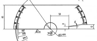
Geometric characteristics of plain bearings
The oil gap is the main geometric parameter of plain bearings. It is equal to the difference between the inner diameter of the bearing and the diameter of the shaft (the inner diameter of the bearing is measured at an angle of 90° to the line dividing the upper and lower bearings).
The size of the oil gap is a very important indicator. Large clearance results in increased oil flow, which reduces oil heating in the bearing, but causes uneven load distribution (it is concentrated on a smaller surface area and increases the likelihood of failure due to fatigue). Also, a large gap produces significant vibration and noise. And too small a gap causes overheating of the oil and a sharp drop in its viscosity.
Typical values of the oil gap C: for passenger cars Cmin = 0.0005D, Cmax = 0.001D, for racing cars Cmin = 0.00075D, Cmax = 0.0015D (where D is the shaft diameter).
Eccentricity is a measure of the out-of-roundness of a bearing. Indeed, the inner surface of the bearing is not completely round. It has a shape reminiscent of a lemon lying on its side. This is achieved due to the variable thickness of the bearing wall, which has a maximum value (T) in the central part and gradually decreases in the direction of the joint.
It is customary to measure the minimum thickness value (Te) at a certain height h in order to exclude the sampling zone in the joint area. The difference between the maximum and minimum thickness values is called eccentricity: T – Te.
The eccentricity caused by the varying wall thickness of the liner is added to the eccentricity caused by the displacement of the shaft relative to the center of the bearing. The presence of eccentricity makes it possible to stabilize the hydrodynamic lubrication regime by creating an oil wedge with a large convergence angle. Recommended eccentricity values: for passenger cars 5–20 µm, for racing cars 15–30 µm.
The fit is necessary to ensure that the bearing fits securely in the seat. A firmly seated bearing has uniform contact with the surface of the seat - this prevents the bearing from moving during operation, ensures maximum heat removal from the friction area and increases the rigidity of the seat. Therefore, the outer diameter of the bearing and its perimeter are always greater than the diameter of the seat and its perimeter.
Because direct measurement of the outer perimeter of a bearing is difficult, another parameter commonly measured is the height of the joint projection (overhang). The height of the joint projection is equal to the difference between the outer perimeter of the bearing half and the perimeter of the seat half.
The liner being tested is installed in the measuring unit and pressed with a certain force F, the magnitude of which is proportional to the cross-sectional area of the bearing wall. The optimal height of the joint projection depends on the diameter of the bearing, the rigidity and thermal expansion of the seat and temperature. Typical lip height values for bearings with a diameter of 40–65 mm: for passenger cars 25–50 µm, for racing cars 50–100 µm.
Despite the most advanced design, materials and technologies, in the operation of internal combustion engines there are cases of wear and damage to bearings. To find and eliminate their causes, knowledge of bearing design is necessary, but not sufficient. More on this in the next article.
Dmitry Kopeliovich
Replacing crankshaft bearings
Remove the hood (see Replacing the hood) and the battery. Drain the oil (see Changing the oil). Drain the coolant (see Replacing the coolant). We remove the radiator together with the thermostat (see Replacing the radiator and Replacing the thermostat).
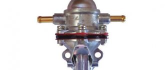
Remove the carburetor (see Replacing the carburetor). Remove the fuel pump (see Replacing the fuel pump). Remove the ignition distributor (see Replacing the ignition distributor). Having sketched the connection order, we disconnect the hoses and wires from the engine, lighten the cylinder block, for which we remove the cylinder head (see Replacing the cylinder head gasket). We remove the generator (see Removing the generator). Remove the starter (see Replacing the starter). Remove the coolant pump (see Replacing the coolant pump). We unscrew the upper or lower nuts securing the engine support cushion (see Replacing the engine support cushion). We unscrew the bolts securing the clutch housing to the engine. We fasten the cables of the lifting device to the block and lift it. By placing a jack under the gearbox and slightly rocking the block, we disconnect the block and the clutch housing.
We install the cylinder block on the stand. Remove the clutch (see Replacing the pressure plate assembly and clutch release bearing). Remove the pulley, camshaft drive cover, oil pump drive chain and gear (see Replacing the camshaft drive chain). Remove the auxiliary drive shaft (see Replacing the auxiliary drive roller). Remove the flywheel and the rear crankshaft cuff holder (see Replacing the rear crankshaft cuff). Using a 10mm wrench, unscrew the fourteen bolts securing the oil pan to the cylinder block...
...and remove it along with the sealing gasket.
Remove the oil pump (see Removing and disassembling the oil pump). Using a 14mm socket, unscrew the two nuts securing the connecting rod cover...
...and remove the connecting rod cover.
Using the wooden handle of the hammer against the connecting rod, we push the piston out of the cylinder.
Similarly, remove the remaining three pistons. Using a 17mm socket, unscrew the two bolts securing the crankshaft main bearing cover...
...and remove it.
In the same way, remove the remaining four main bearing caps. They are marked with marks corresponding to their serial number (count from the toe of the crankshaft). On the last (fifth) cover there are two marks stamped, spaced along the edges.
Marks on the main bearing caps.
We remove the crankshaft.
From the grooves in the bed of the fifth main bearing, we remove two half rings of the crankshaft thrust bearing.
The steel-aluminum liners installed in the beds of the 1st, 2nd, 4th and 5th main bearings have a groove. The shell of the 3rd bearing does not have a groove (similar to the shells installed in the main bearing caps).
We disassemble the crankshaft (see Disassembling the crankshaft). We take out the old main bearing shells. We wash the cylinder block and crankshaft in diesel fuel or kerosene. We blow out their internal cavities and oil channels with compressed air. We wipe the seats of the main bearings with a napkin and install new liners of the appropriate category (nominal or repair). Lubricate the main and connecting rod journals of the crankshaft with engine or transmission oil and install the shaft into the block. We install the main bearing caps with new bearings of the category corresponding to the crankshaft journals installed in them in accordance with the marks. Tighten the cover fastening bolts with a torque wrench (see Appendices).
Checking the rotation of the crankshaft. It should be light and smooth, without jamming or play. We install new steel-aluminum liners into the lower heads and connecting rod caps (see Replacing the piston). Lubricate the piston, rings and cylinder walls with engine oil. We compress the rings with a special device and turn the piston with the “P” mark towards the toe of the crankshaft. With light blows of the wooden handle of a hammer on the bottom of the piston, we press it into the cylinder.
We put on the connecting rod cover and tighten the bolts with a torque wrench (see Appendix). Further assembly of the engine is carried out in the reverse order of disassembly.
How to replace bearings without removing the engine?
To replace the liners successfully, it is not at all necessary to dismantle the motor. If you are assured that it is impossible to get to them without removing and pulling the engine out of the hood, urgently change the car service center. But be sure to take into account one condition - the crankshaft (CV) should not be worn out. Otherwise, you won’t be able to do without removing the engine and completely disassembling it!
Without dismantling the power unit, it is easier to change the connecting rod bearings; it is more difficult to change the main bearings. For the latter case, you need to loosen the fastenings and release the crankshaft by 10-15 cm. Although there is another method, adopted by our grandfathers from ship motorists. The main bearings are pushed out using a soft rivet or bolt, which is inserted into the desired lubrication passage and rotated clockwise. The main thing is that the size of the aluminum insert should be slightly smaller than the hole and not scratch the crankshaft.