Description of design
The VAZ-11194 engine is a gasoline, four-stroke, four-cylinder, in-line, sixteen-valve, with two camshafts. The cylinder operating order is: 1-3-4-2, counting from the generator drive pulley.
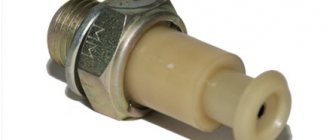
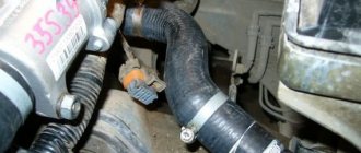
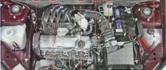
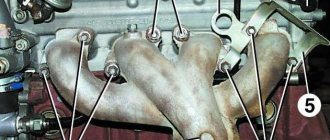
The power supply system is phased distributed fuel injection (Euro-3 toxicity standards). On the right (along the direction of the car) on the engine are located: timing gear and coolant pump drive (toothed belt), generator drive (V-ribbed belt), oil pump, crankshaft position sensor. On the left are: thermostat, coolant temperature sensor, coolant temperature indicator sensor fluids, oil pressure sensor, starter (on the clutch housing).
Front: fuel rail with injectors, knock sensor, oil level indicator, generator (bottom right), phase sensor (top right). Rear: catalytic converter, oil filter, coolant pump supply pipe. On top are the intake manifold, throttle body, coils and spark plugs. The air filter with mass air flow sensor is located to the left of the engine.
Cylinder block
The cylinder block is cast from cast iron, the cylinders are bored directly into the block. The cylinders are honed using Federal Mogul technology. The nominal cylinder diameter is 76.5 mm. For selective engine assembly, depending on the dimensions (diameters) obtained during machining, the cylinders and pistons are divided into three classes every 0.01 mm - A, B, C. The class of each cylinder in accordance with its diameter is marked in Latin letters on the lower plane of the cylinder block .
Cylinder class marking on the bottom plane of the cylinder block
The holes in the cylinder block for the cylinder head mounting screws have an M10x1.25 mm thread (in contrast to the holes with an M12x1.25 mm thread for the cylinder block of the eight-valve VAZ-21114 engine).
At the bottom of the cylinder block there are five crankshaft main bearing supports with removable caps, which are attached to the block with special bolts.
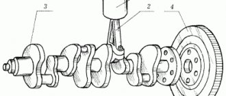
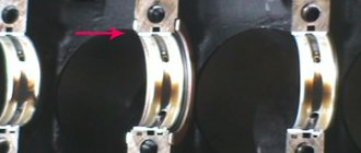
Crankshaft 11183 (marking location shown by arrow) is the same as on the VAZ-21114 engine. Crank radius 37.8 mm
. The engine is equipped with a new lightweight connecting rod and piston group (in comparison with the connecting rod and piston groups of engines of the “tenth” family) manufactured by Federal Mogul, which made it possible to reduce inertial loads.
1 - oil scraper ring;
2 — upper compression ring;
4 - retaining ring;
5 — piston pin;
7 - lower compression ring;
8 — oil scraper ring expander. Connecting rods 11194 are lightweight, steel, I-section. Axial fixation of the connecting rod in the cylinder is along the piston bosses. When manufacturing a connecting rod, a method of controlled breaking off of its cover is used. When assembling such a connecting rod, both of its parts fit almost perfectly, ensuring optimal “steepness” of the hole in the lower head of the connecting rod. The cover is attached to the connecting rod with two screws (with M9x1mm thread), which are screwed into the threaded holes in the connecting rod body. To avoid mixing up the caps during assembly, they, like the connecting rods, are marked with a number (it should be on the same side of the connecting rod and the cap). When assembling the engine, the connecting rod cap fastening screws are tightened to the yield point of the thread - a torque of 20 N*m + 135°. Therefore, each time the engine is reassembled, the screws should be replaced with new ones.
Fracture surfaces of cover 1 and connecting rod 2
A bushing made of antifriction material is pressed into the upper head of the connecting rod.
Connecting rods are not divided into classes based on the diameter of the hole in the upper head for the piston pin, but are divided into two classes based on weight - after 7 g. When assembling the engine, connecting rods of the same weight class are installed in it.
The connecting rod weight class is marked with one or two marks (black lines) on the connecting rod cover
The piston pin is steel, tubular cross-section, “floating” type (can rotate in the piston bosses and in the bushing of the upper connecting rod head). The pin is secured against longitudinal movement by two retaining spring rings located in the grooves of the piston bosses. The outer diameter of the finger is 18.0 mm (there is no division into classes based on the outer diameter of the fingers).
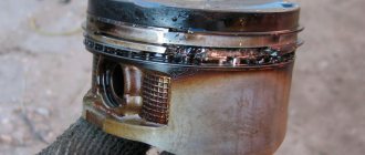
The piston is made of aluminum alloy. The piston is lightweight - the piston skirt is shortened in comparison with the pistons of engines of cars of the “tenth” family. The hole for the piston pin is offset by 0.5 mm from the diametrical plane of the piston, so when installing the piston, you must follow the arrow stamped on its bottom - the arrow should be directed towards the generator drive pulley.
According to the outer diameter of the skirt, pistons, like cylinders, are divided into three classes (A, B, C) every 0.01 mm
Marking on the piston crown
:
1 - piston class designation;
2 - arrow In the upper part of the piston there are three grooves for a “thin” set of piston rings from Getze (part of the Federal Mogul company).
To cool the pistons during engine operation, their bottoms are washed from below with oil through special nozzles pressed into the cylinder block in the area of the second, third, fourth and fifth main bearing supports.
Location of piston cooling nozzles
. Aluminum alloy cylinder head, common to all four cylinders.
Cylinder head assembly (marking shown by arrow)
. The head is centered on the cylinder block with two bushings and secured with ten screws. Between the block and the cylinder head, a two-layer metal gasket with spring-loaded stampings is installed, ensuring the sealing of gas joints and channels.
The use of such a gasket made it possible to reduce the deformation of the cylinder walls that occurs when tightening the cylinder head mounting screws, and, as a result, reduce mechanical losses in the engine.
There are two camshafts located at the top of the cylinder head. The camshaft supports (five supports for each shaft) are detachable. The lower parts of the supports are made in the cylinder head, and the upper parts are made in the camshaft bearing housing, which is bolted to the cylinder head. The holes in the supports are processed in the assembly of the cylinder head with the camshaft bearing housing. If necessary, replace the camshaft bearing housing together with the cylinder head.
The design of the VAZ 1117 Kalina engine. Description of the power supply, cooling and engine control system of the VAZ 1118 Kalina. Elements of the exhaust system of the VAZ 1119 Lada Kalina. Maintenance and operation manual for Lada Kalina, with injection engines 1.4 and 1.6. The car owner can easily diagnose and repair the Lada Kalina car unit on his own in a garage workshop, find faults in electrical equipment, steering, brake system, engine and gearbox. Care tips can also be found in our sections. All Lada Kalina manuals are divided into thematic sections.
Engine VAZ-21114 (Cross section of the engine) 1 - drain plug; 2 — engine sump; 3 - oil filter; 4 — coolant pump; 5 — catalytic collector; b — oxygen concentration sensor; 7 — inlet pipe; 8 — fuel injector; 9 — fuel rail; 10 - receiver; 11 — cylinder head cover; 12 — camshaft bearing cover; 13 - camshaft; 14 — lower crankcase ventilation hose; 15 — valve adjusting washer; 16 - crackers; 17 — pusher; 18— valve springs; 19 — oil deflector cap; 20 — valve guide; 21 - valve; 22 — spark plug; 23 — cylinder head; 24 - piston; 25 — compression rings; 26 — oil scraper ring; 27 — piston pin; 28 — cylinder block; 29 — connecting rod; 30 - crankshaft; 31 — connecting rod cover; 32 — oil level indicator; 33 - oil receiver Lada Kalina engine - gasoline, four-stroke, four-cylinder, in-line, eight-valve, with an overhead camshaft. The cylinder operating order is 1-3-4-2, counting from the crankshaft pulley. Power system - distributed fuel injection (emission standards Euro-2 or Euro-3). The engine with the gearbox and clutch form the power unit - a single unit mounted in the engine compartment on three elastic rubber-metal supports. The front right support is attached to the bracket on the cylinder block, and the front left and rear ones are attached to the brackets on the gearbox housing. The front right and left supports of the power unit, although externally similar, are not interchangeable. On the right (along the direction of the Kalina car) on the engine are located: the Lada Kalina gas distribution mechanism drive and the coolant pump (by a toothed belt), the generator drive (by a serpentine belt), the oil pump, the crankshaft position sensor. On the left are: thermostat, camshaft position sensor, coolant temperature sensor, coolant temperature indicator sensor, starter (on the clutch housing). Front: spark plugs and high voltage wires, ignition coil, knock sensor, oil level indicator, lower crankcase ventilation hose, generator. Rear: receiver with throttle assembly, fuel rail with injectors, intake pipe and catifold, oil filter, oil pressure sensor. The air filter housing with mass air flow sensor is mounted on brackets to the left of the engine. The cylinder block is cast from cast iron, the cylinders are bored directly into the block. The nominal diameter of the cylinder is 82.00 mm with a tolerance of +0.05 mm. The calculated gap between the piston and cylinder (for new parts) should be 0.025-0.045 mm. It is defined as the difference in size between the minimum cylinder diameter and the maximum piston diameter and is ensured by installing a piston of the same class as the cylinder into the cylinder. Depending on the dimensions (diameters) obtained during machining, cylinders and pistons are divided into five classes. The class of each cylinder in accordance with its diameter is marked in Latin letters on the bottom plane of the cylinder block: A -82.00-82.01 B -82.01-82.02 C - 82.02-82.03 D -82.03- 82.04 E - 82.04-82.05 (mm). The maximum permissible cylinder wear is 0.15 mm per diameter. During repairs, the cylinder diameter can be increased by boring by 0.4 or 0.8 mm to accommodate pistons of increased diameter. At the bottom of the cylinder block of the Lada Kalina there are five supports for the crankshaft main bearings with removable covers, which are attached to the block with special bolts. The holes in the cylinder block for the bearings are machined with the covers installed, so the covers are not interchangeable and are marked with marks on the outer surface to distinguish them. On the end surfaces of the middle support of the cylinder block there are slots for thrust half-rings that prevent axial movement of the crankshaft. The half rings must face the grooves (an anti-friction coating is applied to this surface) towards the thrust surfaces of the crankshaft. Half rings are supplied in nominal and 0.127 mm thicker sizes. If the axial clearance (play) of the crankshaft exceeds 0.35 mm, then replace one or both half rings (nominal clearance 0.06-0.26 mm). The main and connecting rod bearing shells are thin-walled steel-aluminium. The upper main bearing shells (installed in the cylinder block) have a groove on the inner surface. The lower main bearing shells are made without a groove, as are the connecting rod bearing shells. Repair liners are produced for crankshaft journals, reduced by 0.25, 0.50, 0.75 and 1.00 mm.
Engine (view from the right along the vehicle) 1 - oil pan; 2 - oil filter; 3 — catalytic collector; 4 — right support bracket of the intake pipe; 5 — coolant pump pipe; b — inlet pipe; 7 - receiver; 8 — fuel rail with injectors; 9 — front cover of the gas distribution mechanism drive; 10 — lower crankcase ventilation hose; 11 - generator; 12 — generator drive belt; 13 — tension roller of the generator belt; 14— bracket for the front right support of the power unit; 15 — generator drive pulley. The crankshaft is made of high-strength cast iron, with five main and four connecting rod journals. The shaft is equipped with eight counterweights cast integrally with it. To supply oil from the main journals to the connecting rods, there are channels whose outlet holes are closed with pressed-in plugs. At the same time, the channels also participate in oil purification: under the influence of centrifugal force, solid particles and resins passing through the filter are thrown back to the plugs. Therefore, during any dismantling of the shaft, it is advisable (and when balancing the shaft, it is mandatory) to clean the channels from accumulated deposits. The plugs cannot be reused - they are replaced with new ones. At the front end (toe) of the crankshaft, a gear pulley for the Lada Kalina camshaft drive and a generator drive pulley are installed on a segment key, which simultaneously serves as a damper for torsional vibrations of the crankshaft (due to the elastic element between the central and outer parts of the pulley). The generator drive pulley has a toothed ring for the crankshaft position sensor. Two teeth out of 60 are missing (forming a cavity) - this is necessary for the controller to determine the top dead center (TDC) of the piston of the first cylinder. At the rear end of the crankshaft, a flywheel is secured with six bolts (the bolts are installed using sealant) through a common washer. It is cast from cast iron and has a pressed steel ring gear, which is used to start the engine with a starter. The flywheel is installed so that the cone-shaped hole located near its crown is opposite the connecting rod journal of the 4th cylinder. This is necessary to determine the TDC of the piston of the first cylinder after engine assembly. The connecting rods are steel, I-section, processed together with the covers. To avoid mixing up the caps during assembly, they, like the connecting rods, are marked with the cylinder number on the Lada Kalina (it should be on the same side of the connecting rod and the cap). A steel-bronze bushing is pressed into the upper head of the connecting rod. Based on the diameter of the hole in the bushing for the piston pin, connecting rods are divided into three classes with a step of 0.004 mm. The class number is stamped on the connecting rod cover. Also, connecting rods are divided into classes based on weight, which is marked with paint or a letter on the connecting rod cover. All engine connecting rods must be of the same weight class. The piston pin is steel, tubular in cross-section, floating type (rotates freely in the piston bosses), secured from falling out by two retaining spring rings located in the grooves of the piston bosses. Based on the outer diameter, three classes of fingers are distinguished (every 0.004 mm): 1 - with a blue mark (smallest diameter), 2 - with green, 3 - with red. The piston is made of aluminum alloy. The piston skirt has a complex shape: barrel-shaped in the longitudinal section, oval in the transverse section. In the upper part of the piston there are three grooves machined for piston rings. The oil ring groove has drillings that go into the bosses. Through these drillings, the oil collected by the ring from the cylinder walls flows to the piston pin. The hole for the piston pin is offset by 1.2 mm from the center plane of the piston, so when installing it, you must follow the arrow stamped on the bottom: it should be directed towards the generator drive pulley. Pistons according to their outer diameter (measured in a plane perpendicular to the piston pin, at a distance of 5 mm from the piston bottom), like cylinders, are divided into five classes (markings are on the piston bottom). Piston diameter by class (nominal size): A - 81.965-81.975 B - 81.975-81.985 C - 81.985-81.995 D - 81.995-82.005 E - 82.005-82.015 (mm). Spare parts include pistons of classes A, C and E (nominal and repair sizes), which is quite sufficient for selecting a piston to a cylinder. At the same time, it is not recommended to install a new piston into a worn cylinder without boring it: the groove under the upper piston ring in the new piston may be slightly higher than in the old one, and the ring may break on the “step” formed in the upper part of the cylinder when it wears out. For pistons of repair sizes, a triangle (+0.4 mm) or a square (+0.8 mm) is knocked out on the bottom. Based on the diameter of the hole for the piston pin, pistons are divided into three classes: 1—21.978-21.982 2—21.982-21.986 3—21.986-21.990 (mm). The piston class based on the diameter of the hole for the piston pin is also stamped on the piston bottom. The piston of the Lada Kalina and the pin must be of the same class.
Engine (front view along the vehicle) 1 — bracket for the front right support of the power unit; 2 - generator; 3 — front timing drive cover; 4 — cylinder head cover; 5 — oil level indicator; 6 - receiver; 7 — oil filler cap; 8 — cylinder head plug; 9 — exhaust pipe; 10 — thermostat housing; 11 — cylinder head; 12— flywheel; 13 — ignition coil; 14 — cylinder block; 15 - spark plugs To reduce the imbalance of the crank mechanism, the pistons of one Lada Kalina engine are selected by weight. Pistons that differ in weight by 5 g are sorted into three groups. The groups correspond to markings on the piston bottom: “G”, “+” and “-”. All pistons on the engine must be of the same group. The piston rings are located in the grooves of the piston. The top two rings are compression rings. They prevent gases from breaking through into the engine crankcase and help remove heat from the piston to the cylinder. To improve wear resistance, the upper compression ring has a chrome-plated barrel-shaped surface. The lower compression ring is of the scraper type (also serves as an oil scraper ring). An oil scraper ring with chrome-plated working edges and an expansion coil spring (expander) is installed in the lower groove of the piston. The nominal height gap between the piston ring and the groove in the piston should be: - for the upper compression ring - 0.04-0.075 mm; — for the lower one — 0.03-0.065 mm; — for oil scraper — 0.02-0.055 mm. The maximum permissible wear gap is 0.15 mm. The cylinder head is made of aluminum alloy, common to all four cylinders. It is centered on the block with two bushings and secured with ten screws. A non-shrinkable metal-reinforced gasket is installed between the block and the head. Its reuse is not permitted. In the upper part of the Lada Kalina cylinder head there are five camshaft supports. The supports are made detachable, and the holes in them are machined together with two bearing housings. Therefore, the bearing housings should be replaced together with the cylinder head. During assembly, an oil-gasoline resistant sealant is applied to the surface of the cylinder head, in the area of the outer camshaft supports. The camshaft of the Lada Kalina is cast, cast iron, five-bearing. It is driven by a toothed belt from the crankshaft of the Lada Kalina. The valve seats and guides are pressed into the cylinder head. The holes in the bushings are finally machined after pressing. On the inner surface of the bushings, grooves resembling threads are made for lubrication: for the intake valve bushings - for the entire length, for the exhaust valves - up to half the length of the hole. Oil deflector caps made of oil-resistant rubber are placed on top of the bushings. The valves are made of steel, the outlet has a head made of heat-resistant steel with a welded bevel. They are arranged in a row, inclined to the plane passing through the axes of the cylinders. The intake valve disc is larger than the exhaust valve disc. The clearance in the valve drive is adjusted by selecting the thickness of a special adjusting washer installed in the pusher socket. Spare parts are supplied with washers with a thickness of 3.00 to 4.50 mm with a pitch of 0.05 mm. The washers are made of 20X steel; their surface is nitrocarburized to increase wear resistance.
Engine (rear view along the vehicle) 1 - flywheel; 2 — left support bracket of the intake pipe; 3 — coolant pump pipe; 4 - hose that drains coolant from the throttle body; 5 — thermostat housing; b - hose supplying coolant to the throttle assembly; 7 — throttle assembly; 8 - receiver; 9 — cylinder head cover; 10 — front timing drive cover; 11 - eye; 12 — cylinder head; 13 - pulley; 14 — oil filter; 15 — right support bracket of the intake pipe; 16 — oil pan; 17 — oil drain plug; 18 — catalytic collector; 19 — cylinder block Pushers are cylindrical cups that move in the holes of the cylinder head and rest on the ends of the valve stems. To increase wear resistance, the surface of the pusher in contact with the valve is cemented. When the engine is running, the pushers rotate due to the displacement of the cam axis relative to the pusher axis by 1 mm, which contributes to their more uniform wear. The valve closes under the action of two springs. Their lower ends rest on the washer, and the upper plate is held in place by two crackers. The folded crackers have the shape of a truncated cone on the outside, and on the inside they are equipped with three persistent flanges that fit into the grooves on the valve stem. Engine lubrication is combined. The main and connecting rod bearings and the support-camshaft journal pairs are lubricated under pressure. Oil is sprayed onto the cylinder walls (further to the piston rings and pins), to the camshaft cam-pushrod pairs and to the valve stems. The remaining components are lubricated by gravity. The oil pump is gear-type, with internal gears and a pressure reducing valve. The drive is carried out from the toe of the crankshaft. The drive gear (smaller diameter) is mounted on two flats on the front end of the crankshaft. The maximum diameter of the socket for the driven (large) gear when worn should not exceed 75.10 mm, the minimum width of the segment on the body separating the drive and driven gears is 3.40 mm. The axial clearance should not exceed 0.12 mm for the drive gear and 0.15 mm for the driven gear. The oil receiver is bolted to the second main bearing cover and the pump housing. The Lada Kalina oil filter is full-flow, with a steel body, non-separable, with bypass and anti-drainage valves. The crankcase ventilation system is a closed type, with gases being removed through an oil separator (in the cylinder head cover) into the engine intake system without entering the atmosphere. Crankcase gas from the lower part of the engine crankcase enters the cylinder head cover through the lower hose and is then discharged through two circuits: the main circuit and the idle circuit. Through the main circuit, crankcase gas is discharged at partial and full load modes into the space in front of the throttle valve. Through the idle circuit, crankcase gas is diverted into the space behind the throttle valve both in partial and full load modes, and in idle mode. To reduce the vacuum in the Lada Kalina engine crankcase to a normal value, a jet with a 1.7 mm hole is installed in the idle circuit.
Detailed steps for checking compression
So, the first thing you need to do is warm up Kalina to operating temperature, and then relieve the pressure of the fuel system. To do this, remove the pump fuse and start the engine so that all the fuel is consumed - the engine should stall. You can read more about this at the very beginning of the material on replacing the fuel filter.
Then you need to complete the following steps. First, disconnect the wire block from the ignition module.
Now we remove the high-voltage wires from all four spark plugs:
Then we unscrew all the spark plugs and remove them from the cylinder head.
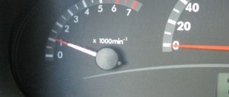
Next, everything is quite simple. We connect the compression gauge fitting to the first cylinder - in the place for the spark plug. Next you will need an assistant. One person must sit in the passenger compartment and, with the gas pedal fully depressed, start the car (turn the starter).
At this time, you observe the readings of the device. It is necessary to check, that is, turn the starter, until the compression meter readings stop increasing. This usually happens in 4 compression cycles.
Description
Like all previous models, the VAZ 11183 engine is a classic four-stroke, in-line, 4-cylinder power unit with an overhead camshaft.
The increase in cylinder volume was achieved through the use of a higher cylinder block than that of the prototype. Its height is 2.3 mm higher than the height of the 2111 engine block and is 197.1 mm (from the crankshaft axis to the top surface). The diameter of the cylinders did not change, but the dimensions and shape of the combustion chamber had to be changed.
The cylinder head is made of aluminum alloy. A camshaft is installed in its upper part, and special ducts are cast in the lower part, designed to supply coolant to the combustion chambers. The same channels are also available in the cylinder block housing.
The crankshaft and camshaft of the engine are cast from cast iron, the pistons are made from aluminum alloy. Forged connecting rods (steel).
Compression in cylinders Kalina 8 valves
Engine compression indicates the condition of the engine, its service life, power, and torque. This procedure must be performed every 20-30 thousand kilometers, as well as before purchasing a car. Even when checking at a service center, YOU will need knowledge of “how to correctly measure compression”, because... Servicemen love to deceive and make money from you.
Compression is the pressure created in the cylinder at the end of the compression stroke.
Another term is appropriate here: Engine compression ratio.
The engine compression ratio is expressed in the following ratio: compression/combustion chamber volume
What compression should be in the cylinders of a VAZ engine?
Normal engine compression is at least 10 bar (1.0 MPa), and the difference between the cylinders should not exceed 1 bar (0.1 MPa). If your compression is 11-12-11-12 from cylinders 1 to 4, then the engine is fine, but do not forget to adjust the valves every 2500 km. If you have 11-9-12-11, then you need to look for the reason and make repairs, because Driving in such conditions will only kill the engine.
How much should the ideal compression be?
The ideal compression should be 14 bar for an 8-valve engine in each cylinder with minimal variation (14-14-14-14).
Compression measuring device
How to measure compression?
There is a special device for measuring compression, it is called a “compressometer”. These devices come in two types: clamping, universal, flexible and threaded.
How to measure engine compression?
To check the compression we need a spark plug wrench, a charged battery and a compression gauge. You also can’t do without an assistant.
1) Warm up the engine to operating temperature
2) Turn out all the candles
3) Install a device for measuring compression (compressometer) into the spark plug hole that appears.
4) The assistant presses the gas all the way and starts the car within 6-10 seconds.
5) We remember the readings of the compression gauge and carry out similar operations on the remaining cylinders.
Description of the engine design Lada 11183 8 valves
The unit has a 4-cylinder cast iron cylinder block and an 8-valve aluminum head with an overhead camshaft, the cams actuate the valves via pushrods. There are no hydraulic compensators here; valve clearances are adjusted by selecting steel washers.
The cylinder block of this power unit is essentially not very different from the VAZ 21083 engine, but the head naturally already has an injector. The increased piston stroke from 71 to 75.6 mm increased the working volume from 1.5 to 1.6 liters, and phased injection was replaced by pairwise parallel injection.
The timing belt drive has a manual tensioning mechanism and often has to be tightened. The good news for drivers is the fact that due to the manufacturer’s use of pistons with holes on the bottom, if the valve belt breaks, the valve almost never bends.
From 2011 to 2021, a seriously modernized version of this power unit was produced with a large receiver and an E-gas electronic throttle control system. It was distinguished by increased hp to 82. 132 Nm power and own index 11183-50.
The guy installs a lightweight piston from engine 11186 on this engine
The VAZ 11183 engine was designed for the Kalina car. The 21114 engine was taken as the basis, the engine markings changed (1 instead of 2 at the beginning of the internal combustion engine designation), the design of the crankshaft and cylinder head. Changes were necessary to increase the volume to 1.6 liters, and the use of existing parts was necessary to reduce the cost of the power drive.
Compression measurement
We carry out a compression test for a general assessment of the technical condition of the parts of the cylinder-piston group and the engine valve mechanism. We carry out the check with an assistant on the engine, warmed up to operating temperature. We relieve the pressure in the engine power supply system (see “Replacing the fuel filter”) and do not replace the fuel pump fuse. We unscrew the spark plugs from the holes in the cylinder head (see “Checking the condition and replacing the spark plugs”). Disconnect the engine control system wiring harness block from the ignition coil (see “Removing the ignition coil”)
We install the tip of the compression gauge into the spark plug hole of the cylinder head. We turn the crankshaft with the starter with the gas pedal fully pressed for 2-4 s (the pressure gauge readings should stop increasing). We record the pressure gauge reading and relieve the pressure in the compression gauge.
Lada Kalina. Low compression in the engine: reasons
Reasons for low compression
Low compression is a bad indicator for the engine. As for low compression, in this case the engine starts poorly when cold, smokes, does not pull, noticeably overuses oil, fuel, etc. In gasoline engines, when trying to start a unit with low compression, the spark plugs are additionally flooded, which further complicates the situation.
In practice, a decrease in compression or its complete absence most often occurs for the following reasons:
For example, engine wear and distortion of cylinder geometry, as well as the formation of scoring on the cylinder walls as a result of metal shavings can lead to a decrease in compression. Problems with the cylinder head gasket will indicate that the seal will be compromised. Also, after the internal combustion engine overheats, a crack may appear in the block or head. A still loose fit (as a result of coking or improper adjustment), destruction of the valve disc (often from burnout) leads to the fact that proper closure does not occur, and compression drops.
Natural wear and tear of the engine should not be excluded, when in a used engine the gap between the cylinder wall and the piston increases. In parallel, it is worth mentioning problems with the pistons themselves (destruction, burnout, etc.).
If the engine has no compression or low compression
A decrease in compression indicates the need to repair the power unit, which involves disassembling and troubleshooting the internal combustion engine. Only after these procedures can you get an idea of the condition of the CPG and timing belt, as well as other elements and components of the engine.
However, it also happens that the cause of a decrease in compression can be eliminated without disassembling the engine. We are talking about removing coke, carbon deposits and deposits. This solution allows you to clean the combustion chamber, restore mobility to the piston rings, remove carbon deposits from the valves and ensure their tight fit.
To more accurately determine how serious the problem is, without disassembling the internal combustion engine, you first need to pour 7-8 “cubes” of engine oil into the problem cylinders. Then the compression needs to be measured again. If adding oil does not change the situation, then valve related problems are likely. If the compression increases after adding oil, then you should look for the problem in the wear of the CPG elements. So, in this case, the rings could have stuck, and decoking the piston rings in some cases can correct the situation.
Let us immediately note that this method will not necessarily help, but it is worth a try, especially since the owner will not require significant financial investments.
In short, to decarbonize the engine, you need to purchase a special cleaning fluid. Next, you need to unscrew the spark plugs and pour 30-40 grams into each spark plug hole. Then the spark plugs are not screwed in (you can cover the holes with a clean rag), and the car itself should be left in the garage for 10-12 hours. After the specified time, you will need to crank the engine with the starter with the spark plugs removed. Next, the spark plugs are cleaned and reinstalled. Please note that after pouring the decarbonizer, you must not immediately screw in the spark plugs and try to start the engine! In this case, residual liquid in the combustion chamber can cause water hammer.
Disassembly and assembly of the Kalina engine
Tool:
- Open-end wrench 10 mm
- Straight box spanner 13 mm
- Straight box spanner 17 mm
- Torque wrench
- Driver for socket attachment
- Knob attachment 10 mm
- Knob attachment 14 mm
- Knob attachment 17 mm
- Extension for wrench attachment
- Rubber hammer
- Knife
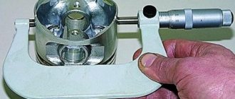
- Bore gauge
- Micrometer
- Medium flat screwdriver
- Mandrel 18 mm
- Set of flat styli
Parts and consumables:
- Engine oil
- Rags
1. After dismantling, we install the engine on a stand for disassembly. We remove the generator, cylinder head, flywheel, oil filter.
2. Using a 17 spanner we unscrew two bolts 1 of the lower fastening, and with a 13 spanner we unscrew bolt 2 of the upper fastening of the front right support bracket of the power unit.
3. Remove the front right support bracket.
4. Using a 13mm socket, unscrew the three bolts securing the generator bracket.
5. Remove the generator bracket.
6. Remove the engine oil pan as described here. Using a 10" socket with an extension, unscrew two bolts 1 securing the oil receiver to the main bearing cover and bolt 2 securing the oil receiver to the oil pump housing.
7. Remove the oil pump as described here. Having unscrewed the two bolts securing the supply pipe of the coolant pump to the cylinder block with a 10mm wrench, remove the pipe and its sealing gasket. Using a 10mm socket, unscrew the six bolts securing the crankshaft rear oil seal holder.
8. Remove the rear oil seal holder.
9. The connection between the oil seal holder and the cylinder block is sealed with a gasket.
10. Using a 14mm socket, unscrew the two nuts on the connecting rod cover bolts (the connecting rod should be at bottom dead center).
11. Lightly tap the side surfaces of the connecting rod cap with a hammer with a plastic tip (or soft metal).
12. And we begin to remove the connecting rod cover.
13. Remove the connecting rod bearing shell from the cover.
14. Using the wooden handle of a hammer against the ends of the rods of the connecting rod bolts, we move the lower head of the connecting rod from the crankshaft journal.
15. Remove the piston and connecting rod from the cylinder.
16. We remove the upper connecting rod bearing from the lower head of the connecting rod. Similarly, we remove the pistons with connecting rods from other cylinders. If the parts of the connecting rod and piston group are not damaged and have little wear, they can be used again. Therefore, during disassembly, we mark the parts so that during subsequent assembly they will be installed in their places. Using your fingers, carefully (without exerting much force) open the lock of the upper compression ring.
17. We remove it from the piston groove.
18. Similarly, remove the lower compression ring and, unclamping the lock, remove the oil scraper ring.
19. Remove the oil scraper ring expander.
20. To remove the piston from the connecting rod, use a screwdriver to pry up the retaining ring of the piston pin and remove it from the annular groove of the piston boss. In the same way, remove the other piston pin retaining ring.
21. Use a mandrel to push out the piston pin.
22. Remove the piston from the upper end of the connecting rod. We carry out similar operations with other pistons.
23. Using a 17mm socket, unscrew the two bolts securing the crankshaft main bearing cover.
24. Remove the main bearing cap.
25. Remove the lower crankshaft main bearing shell from the cover. In the same way, remove four more caps of the crankshaft main bearings.
26. We remove the crankshaft from the cylinder block and then remove the two thrust half-rings of the crankshaft (shown by arrows) from the grooves in the support of the third main bearing (in the cylinder block).
27. We remove the upper crankshaft main bearing shells from the cylinder block supports.
28. Using a sharpened tool, remove the remaining sealant from the flattened plane of the cylinder block under the oil pan.
29. In the same way we clean the remains of the cylinder head gasket.
30. We clean the mating surfaces of the cylinder block under the coolant pump pipe and the crankshaft rear oil seal holder.
31. After disassembling the engine, we thoroughly wash and clean the parts of the cylinder-piston group from carbon deposits to check their technical condition.
32. To determine cylinder wear with a bore gauge, we measure the diameter of the cylinder in four zones (at a distance of 8, 15, 50, and 90 mm from the upper plane of the cylinder block) and in two directions (parallel and perpendicular to the axis of the crankshaft). In the area of the first belt (up to 8 mm), the cylinder practically does not wear out, therefore, by the difference in measurements in the first and other belts, the wear of the cylinder can be determined. If the wear of the cylinders exceeds 0.15 mm, it is necessary to bore and hone the cylinders at the service station to the repair size (increased by 0.4 or 0.8 mm).
33. To determine the wear of the piston skirt, use a micrometer to measure its diameter in a plane perpendicular to the piston pin axis, at a distance of 55 mm from the piston bottom. Using a micrometer, we measure the diameters of all main and connecting rod journals of the crankshaft in two diametrically opposite planes.
34. We grind the crankshaft journals to the nearest repair size if wear or out-of-roundness is greater than 0.03 mm, and also if there are burrs and marks on the journals. After grinding the crankshaft journals, it is necessary to remove the oil channel plugs. Then we thoroughly rinse and blow through the channels with compressed air to remove any remaining abrasive. We grind the crankshaft journals, remove and install new plugs at the service station.
35. We assemble the engine in reverse order. We install new crankshaft main bearing shells of nominal or repair size (after grinding the shaft journals). We install liners with grooves on the working surface into the cylinder block supports, and without grooves into the main bearing caps. Lubricate the bearings with engine oil and place the crankshaft in the cylinder block supports. We insert thrust half-rings lubricated with engine oil into the grooves of the third main bearing support.
36. The surfaces of the half rings with antifriction coating (they have grooves) must face the thrust surfaces of the crankshaft.
37. We install the main bearing caps in accordance with the marks (see figure) marked on their outer surface (the caps are counted from the timing belt drive side). When installing, we orient the covers so that the marks on them are located closer to the front side of the cylinder block (the side where the generator is mounted). In this case, the locks of the upper and lower shells of each main bearing are located on one side.
Marks on the main bearing caps
38. Tighten the main bearing cap bolts to a torque of 68-84 Nm.
39. Pistons for cylinders are selected according to classes of cylinder diameters and piston skirts. The diameter class of each cylinder (in our case, this is class C) is stamped opposite the cylinder on the lower plane of the block (the mounting plane of the oil pan).
40. The piston skirt diameter class is marked on the piston crown. Pistons of the same weight class are installed in the engine.
Marking on the piston bottom: 2 - piston class based on the diameter of the pin hole; C - piston skirt diameter class; — when installing the piston into the cylinder, the arrow should be directed towards the timing drive; G - piston class by mass.
41. Marking of connecting rod classes by weight and diameter of the hole for the piston pin is applied on the connecting rod cover.
Marking on the connecting rod cover: H – connecting rod weight class; 2 - class of connecting rod based on the diameter of the hole for the piston pin.
42. Before assembling the connecting rod and piston group from new parts, it is necessary to select pins for the pistons and connecting rods. The class of the piston and connecting rod according to the diameter of the pin holes must correspond to the class of the pin diameter. A correctly selected piston pin, lubricated with engine oil, should fit into the hole in the upper head of the connecting rod with a pressing force of the thumb and not fall out of it in a vertical position.
43. When assembling the piston and connecting rod, we orient them so that when installed in the cylinder, the serial number stamped on the connecting rod is located closer to the rear wall of the cylinder block (on which the oil filter is located). Before installing piston rings on the piston, it is necessary to check the thermal clearances in the ring locks. To do this, insert the piston ring into the cylinder in which it will be installed during assembly and align the ring with the bottom of the piston.
44. Using a set of flat feeler gauges, we check the gap in the piston ring lock. The gap should be 0.25-0.45 mm. The maximum permissible gap for wear is 1 mm.
45. Lubricate the grooves on the pistons under the piston rings with engine oil. Install the rings on the pistons. We install the lower compression ring with the groove (“scraper”) down. If the ring is marked “TOP” or “TOP”, place the ring with the mark facing up.
46. We arrange the rings as follows:
- We orient the upper compression ring lock at an angle of about 45° to the piston pin axis;
- the lock of the lower compression ring is at an angle of 180° to the axis of the lock of the upper ring;
- The oil scraper ring lock is at an angle of 90° to the axis of the upper compression ring lock.
47. When installing the oil scraper ring, place the expander joint on the side opposite to the ring lock. Before installing the parts of the cylinder-piston group, lubricate the cylinders, pistons with rings and connecting rod bearings of the crankshaft with engine oil.
48. Before installing the piston into the cylinder, we put an adjustable mandrel on the piston and, tightening the mandrel, compress the piston rings.
49. Install the piston with connecting rod into the cylinder. In this case, the connecting rod journal of the crankshaft of this cylinder should be in the position of the bottom dead center. Using the hammer handle against the bottom of the piston, we push it into the cylinder.
50. Having removed the mandrel, use the handle of a hammer to push the piston into the cylinder until it stops. At the same time, we control the fit of the connecting rod lower head shell on the crankshaft journal.
51. When installing the connecting rod cap, the serial numbers on the connecting rod and the cap must match and be located on the same side of the connecting rod.
52. We carry out further engine assembly in reverse order.
The article is missing:
- Photo of the instrument
- Photos of parts and consumables
- High-quality photos of repairs
Source: https://wiki.zr.ru/83_Repair_Kalina
What compression should be on a Chevrolet Niva
Hi all! I encountered the following problem: when measuring compression, the compression meter does not show any values. In this case, the starter turns without stopping until you release the key. Could it be a problem with the sensors? The engine has been partially disassembled (the accessory belt has been removed, the radiator and cooling system have been removed). Or has the kirdyk head come?
Comments 11
I was present on an interesting occasion when a broken head gasket was being replaced on a shnivy. And after assembly it does not start, there is no compression. It turns out that before assembly it was necessary to remove the oil from the hydraulics and compress them until they stop. Otherwise there will be no compression.
Did you remove the camshaft?
I removed the camshaft, but as it turned out I had simple adjusting bolts and there were no hydraulic compensators. When I changed the oil scraper, it started up without any problems.
I didn't set the labels correctly.
Yes, I bent the valves, how much you can harp on the same thing. Take off the head, install new valves, grind them in. Business day.
Doesn't it show in any cylinder? Prehistory - why did you start measuring compression? Not a single sensor affects the compression... By ear - when cranking the engine, if there is a “squeak” sound from the cylinders quite loudly, then there is compression, the compression gauge turns out to be broken. The day before yesterday we picked up a new one at the store, it seems 5.5 maximum, I checked with mine, it seems 12.5 on the 21083 engine, it happens.
There are no sprays, but the air is spitting out. The backstory is scary. I changed the chain, put it on the wrong marks, spun it - it didn’t start. Now I have assembled it according to the marks and am checking to see if the valves are bent. The compression gauge is working, I checked it on 2 cars. Maybe the battery is dead?
Then most likely the valves are bad. Even on the podskvshim there will be compression
There are no sprays, but the air is spitting out. The backstory is scary. I changed the chain, put it on the wrong marks, spun it - it didn’t start. Now I have assembled it according to the marks and am checking to see if the valves are bent. The compression gauge is working, I checked it on 2 cars. Maybe the battery is dead?
You can check the valves like this: put the hose to the cylinder (from where you unscrewed the spark plug) and blow, if it blows easily or hisses from another cylinder, it means the valves...
There are no sprays, but the air is spitting out. The backstory is scary. I changed the chain, put it on the wrong marks, spun it - it didn’t start. Now I have assembled it according to the marks and am checking to see if the valves are bent. The compression gauge is working, I checked it on 2 cars. Maybe the battery is dead?
Cylinder pressure indicators
First of all, it is necessary to understand what compression is and why it excites Niva car owners. This term refers to the pressure in the cylinder when it is measured by a pressure gauge at engine speed. Nowhere in the technical documentation that came with the car will you find the concept of compression, although many motorists and auto mechanics drive them.
But among the technical parameters of a car it is easy to find such a parameter as the compression ratio. As for the regular VAZ 21213, but for the Chevrolet Niva its value is the same and equal to 9.3. The reason is that all these cars have the same engine. modernized 2106 with a strengthened crankshaft and an increased piston diameter to 82 mm.
Compression ratio and compression ratio are two different metrics with little to no relationship to each other. The latter does not change and does not depend on the degree of wear of the power unit. It shows how much the air/fuel mixture is compressed into the cylinder as the piston moves to top dead center. The compression ratio is calculated as the ratio of the total volume of the cylinder to the value of the combustion chamber, where the combustible mixture is compressed and flashes.
Piston rings and connecting rod bearings - replacement
Piston rings are replaced when repairing the connecting rod and piston group, if they are worn out or damaged. Also, rings are replaced during engine overhauls.
To complete the job, you will need a piston ring mandrel.
Removal
1. Remove the cylinder head.
2. Removing the engine oil pan
3. We remove the oil intake.
4. Turning the crankshaft by the bolt securing its pulley with a 17 mm wrench, set the piston of the first cylinder to the lower position.
5. Using a TORX E10 wrench, unscrew the two nuts securing the connecting rod cover of the first cylinder.
6. Remove the connecting rod cover.
7. Place the hammer handle on the piston and push it up.
8. Remove the piston from the cylinder.
9. We take out the liners from the connecting rod and its cover.
10. We fix the piston by the connecting rod in a vice. Slightly spreading the ring lock, remove the upper compression ring. Similarly, remove the lower compression ring, oil scraper ring and its expander.
The rings are thin and to avoid breaking them, cut a strip from a plastic bottle slightly shorter than the circumference of the piston. Place the edge of this strip under the lock of the upper compression ring, and then in a circle under the entire ring.
Remove the strip along with the ring from the piston. Remove the second compression and oil ring in the same way.
The advisability of replacing the rings depends on the degree of wear of the cylinders. Small uniform wear of the cylinders (within 0.05 mm) can be compensated by installing a piston of a different class with a larger diameter (see “Piston and connecting rod replacement”)
Installation
1. Thoroughly clean the piston of carbon and deposits. We inspect the piston, connecting rod and pin. Cracks on them are unacceptable.
We select new rings in accordance with the piston diameter - nominal or repair size.
2. Before installing new rings, use a set of feeler gauges to measure the gap between the piston ring and the wall of the groove in which the ring will be installed.
Permissible clearances between groove walls and piston rings
Table 8.1.3
| Ring | Gap, mm |
| Upper compression ring | 0,04-0,075 |
| Bottom compression ring | 0,03-0,065 |
| Oil scraper ring | 0,02-0,055 |
The permissible gaps between the groove walls and the piston rings are shown in table. 8.1.3. If the gap exceeds the maximum allowable, the piston must be replaced.
3. To select piston rings based on the thermal gap, install the rings one by one into the block cylinder to a depth of 20-30 mm and use a set of flat feeler gauges to determine the gap in the lock.
Comment
The maximum permissible thermal gap during wear (for used rings) is 1 mm, the gap for new rings is 0.25-0.45 mm. If the gap exceeds the maximum allowable, the ring must be replaced.
4. We put the rings on the piston. In this case, the oil scraper ring...
...and install the compression ring with the word “TOP” facing up.
We install new rings on the piston, starting with the oil ring expander.
Using a mandrel, we put on the oil scraper ring, and then the lower compression ring (we put the rings on the mandrel and carefully move them down until they are installed in the groove).
We put on the upper compression ring without a mandrel: having spread the ring lock (no more than is required to put the ring on the piston), we first place the lock on the piston, and then the back part of the ring.
5. We rotate their locks so that they are located at an angle of 120° relative to each other. The expander lock must be rotated 180° relative to the ring lock.
6. Lubricate the cylinder wall with clean engine oil...
...and the outer surface of the piston.
7. We put the mandrel on the piston and compress the rings with it, periodically lightly tapping the mandrel with the handle of a hammer to self-install the rings.
The connecting rod caps are not interchangeable. The engine is equipped with “chopped connecting rods”, the covers of which are made using a special method. The contact surfaces of the cap and the connecting rod are uneven, which ensures a perfect fit of the parts during assembly.
8. We wipe dry the liners in the connecting rod and the cover and install the liners in them.
9. Lubricate the inner surface of the liners with clean engine oil.
10. Install the piston into the block cylinder.
The arrow on the piston crown should point towards the crankshaft pulley.
11. Pressing the mandrel against the block and tapping the piston bottom with the handle of a hammer, we recess the piston into the cylinder (at the same time we control the movement of the connecting rod to the crankshaft journal).
12. Install the cover on the connecting rod and tighten the bolts to a torque of 43.32-53.51 PM (4.42-5.46 kgf-m).
We assemble and install the other three pistons in the same way.
After installing all the pistons, we assemble the engine in the reverse order of disassembling it.
Analysis of test results
Based on the measurement results obtained, conclusions can be drawn in accordance with recommendations developed over many years of practice:
When carrying out the analysis, it is necessary to take into account an important point - the uniformity of readings in all cylinders.
If over time the pressure gradually and equally decreases in each of them, then there is a natural process of wear of the piston rings, piston walls and cylinders. If 1 or 2 measurements differ sharply from the others, then regarding repairs you need to be guided by the worst indicators.
Increased pressure
A paradoxical situation with increased compression occurs when motor lubricant enters the piston rings from above, from the side of the combustion chamber. It seals the interface and when measured the pressure surge reaches 14-15 bar.
Cause. in worn valve seals, which provide a lot of lubricant to the Niva’s combustion chamber. The exhaust fumes are desperate, the oil consumption is high, but the pistons and rings have nothing to do with it. The fault is detected when the valve cover is opened and the tappets are removed from the valves. Unsuitable caps are “oaky” to the touch or covered with cracks. Oil seals can be changed without disassembling the power unit.
Source