Content
- 1 Design of the idle system.
- 2 Removal and disassembly:
- 3 Cleaning the CXX
- 4 Assembly
- 5 Adjustments. 5.1 1. Adjusting the throttle position.
- 5.2 2. Adjustment of TPS (throttle position sensor)
- 5.3 Adjusting the position of the bimetallic spring:
- 5.4 “Retraining” after cleaning.
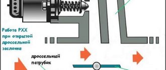
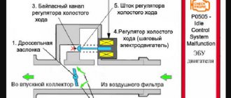
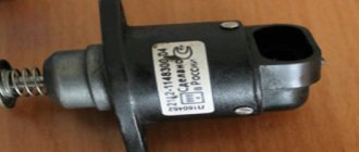
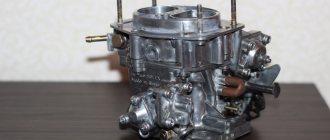
The idle air valve is installed on the throttle body and regulates the capacity of the air channel located bypassing the throttle (bypass or bypass channel).
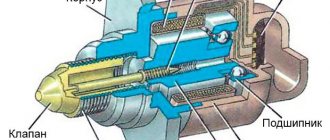
The channel capacity determines the engine idle speed. The channel capacity is adjusted by turning the valve spool to a certain angle. The valve opening angle required for normal engine operation is set using the magnetic field created by the solenoids (coils) of the regulator. To prevent the engine from stopping in the event of a malfunction in the IAC electrical circuit, a damper opening mechanism is provided at the other end of the valve axis, consisting of a bimetallic spring (spiral), a stop and a valve axis lever. Depending on the temperature of the coolant in the engine, the spring changes its stiffness, as a result of which the position of the stop and the angle of rotation of the valve changes. The XX speed of the warmed-up engine is higher than normal (1100-1200 rpm). You should not change the position of the bimetallic spring without good reason! If the spring position is incorrect, the electrical circuit simply cannot cope with adjusting the idle speed. You can see how this manifests itself here:
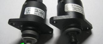
— The bimetallic spring is insurance in case of failure of the electromagnetic valve of the XX regulator. — If you turn off the XX, the engine will run on one bimetallic spring. When cold it opens the valve and closes it when it warms up. — If you remove the spring, the engine will run on one solenoid valve. When cold the valve will be open more and will close as it warms up. — The bimetallic spring and coils do not interfere with each other much, since their action is aimed at the same thing. — The bimetallic spring alone should provide 1000-1200 rpm on a warm idle without consumers. Why not 700-800? Because it is not subject to the brain, it is subject only to the coolant temperature that washes it. This means that it cannot open the valve slightly as consumers are connected. A bimetallic spring holds the valve to a certain degree of opening and as consumers are connected, the revolutions will drop (at maximum load I dropped from 1160 to 790). Based on the above, the bimetallic spring has only 2 (two) settings: 1. Correct orientation - when cold it should open the valve, and when it warms up - close it. 2. Correct position - on a warm idle without load with the idle switch turned off, the engine speed should be in the range of 1000-1200.
1. Loosen the clamp, remove the temperature sensor, remove the air filter cover.
Photo1
2. Remove the air filter pipe from the BDZ. Unscrew the clamp screw (1). Pull out the hose from the BDZ (2). We pull out the hoses and the cable from the connection pipe (3,4,5). Then we pull the pipe off the BDZ. (photo2)
Photo2
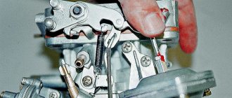
3. Unscrew the bolts securing the throttle valve opening cable (item 1 in photo 3), before unscrewing the cable casing, then remove the coolant and vacuum supply pipes. (p2 photo3) In order. The one closest to you is the coolant hose. In the middle is a vacuum. The furthest one is the coolant hose.
Attention
! Be sure to let the car cool down, otherwise the coolant will be very hot! And also, prepare bolts to plug the hoses. I don't remember the size. I selected the appropriate ones. (photo 3)
photo3
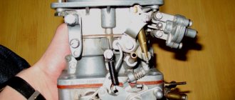
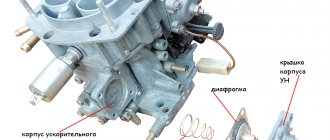
4. Remove the chips from the throttle position sensor (1) and the idle air valve (2). Unscrew the 2 bolts and 2 nuts securing the throttle valve (3 – 4) (photo 4)
Photo4.
5.Remove the electrical winding of the idle speed valve (1). Remove the valve itself (2).
Attention!!!
Carefully pull off the valve so as not to damage the gasket!!! All the bolts are difficult to remove. I had to ask for help. An acquaintance held the damper tightly, pressing it to his body, and I tore off the bolts. (Photo5)
Photo5
Cleaning materials - brush, carburetor cleaner (carb cleaner) We wash the inside of the valve to remove carbon deposits. (black coating on Photo 6) In especially severe cases, it is recommended to soak the carbon deposits in the valve for an hour or two in a cleaner. The result of high-quality cleaning should be a smooth, easy, “wind-blown” rotation of the valve.
Photo6
Afterwards, without disassembling, we clean the throttle valve assembly (body, valve, channels) - spraying with carb cleaner and carefully using a toothbrush.
After washing the valve, apply a small layer of sealant to the electromagnet and screw it into place. If the gasket is good, carefully screw the valve into place.
Then collect in reverse order.
Note: Photo 5 and photo 6 were taken from an article on cleaning the IAC for the 7A-FE engine. (https://www.toyota-club.net/files/05-09- … -clear.htm)
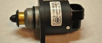
Where is the idle speed sensor located and how to replace it
KXX on the throttle valve
This device on Toyota cars is installed on the throttle body using several screws. In some cases, these screws may have specially drilled heads to make removal difficult. Then experts recommend completely dismantling the damper to avoid damage to the valve fasteners.
Common signs of a bad idle air valve include extreme roughness when idling. In this case, there are jumps or dips when the number of revolutions increases, a decrease in speed when the load is on, when they should only increase, or a complete stop of the car engine.
The cause of sensor malfunction is usually its contamination due to the low quality of the fuel mixture. When the engine starts, the computer sets the valve to the factory-set value. This is a problem, since the machine is not able to determine the level of contamination of the valve and the amount of various foreign deposits on it that interfere with the normal operation of the sensor.
This type of problem can be resolved by simply cleaning or replacing the idle speed sensor. To do this, you need to disconnect the valve connector and unscrew the mounting bolts. Attention, all this work must be carried out strictly with the ignition off. After replacing or repairing the device, you must reinstall it. Correct installation is checked by measuring the distance between the cone needle and the flange. In normal condition, it should not exceed 23 millimeters. When installing the sensor, it is recommended to lubricate the O-ring with special high-quality motor oil.
Adjusting the throttle position.
The primer says that when the damper is CLOSED there should be no gap between the stop screw and the damper drive stop. This is exactly the thrust screw. Its purpose is to prevent wear of the damper body and prevent the damper from biting. This is NOT an idle speed adjusting screw. This is why on many machines the screw head is cut off at the factory. If it so happens that someone has already turned the screw, then you need to ensure that the damper is completely closed (it’s better to check on a clean assembly for light) and check the assembly for absence of snagging. The damper should “start” smoothly, without any additional effort to “pull it off”.
Adjusting the TPS (throttle position sensor)
TPS can be 3-pin and 4-pin. (https://www.carina-e.ru/viewtopic.php?p=244295#244295)
WhiteGoose wrote:
«I suspect that initially the IDL signal was used in KarineE, and 4 wires went to the brain. But at some point, the method of recognizing the XX sign changed from physical (by a break in the IDL signal) to logical (by voltage on VTA). At the same time, the TPS itself remained the same, but the 4th wiring to the IDL contact was eliminated as unnecessary.
«
The difference between the sensors is in the way they inform the control unit about a fully closed damper. The 4-pin has an IDL contact, the control unit detects a closed damper by the presence of contact between IDL and E2. Adjustment (according to the manual):
Disconnect the TPS connector. Insert a 0.4 mm probe between the stop and the damper lever, measure the electrical resistance between the sensor contacts.
IDL - E2
- no more than 2.3 KOhm (maybe significantly less - this is normal).
Instead of a 0.4mm probe, use a 0.9mm probe. The resistance between IDL and E2 should be infinite (open). During operation, the 3-pin TPS changes the voltage at the VTA pin relative to E2. When the damper is closed, it should be from 0.3 to 0.8V - https://www.carina-e.ru/viewtopic.php?p=136785#136785
Adjustment (method described by next402):
Let me sketch out a small manual for setting up this miracle called TPS: Actually, as you like, but I got used to setting it up without removing the DZ unit. To begin with, there is no rush, it’s better to do it properly once than to redo it later. We slightly loosen the sensor mounting screws, insert a 0.7 probe (for 3S-FE), use a multimeter to cling to IDL - E2 and, by tapping a little with a small hammer, literally on the millimeter, we catch the moment when the conductivity disappears (the multimeter will show infinite resistance). We fix the top bolt and check all the contacts according to the manual, fix the bottom bolt and check EVERYTHING again with all the probes. Let's reset and learn =) In my case, the mistake was that I adjusted the sensor by moving it by hand, of course there was no talk of any millimeters there......=) I would also note that the resistance value on the IDL - E2 contacts does not matter, it is important so that it does not exceed the specified limit, in my case it was 30 Ohms, which was misleading (it seemed too small, because the manual indicated 2.3 kOhms or less, i.e. the lower limit was not indicated)
Method for adjusting TPS using the program from chem407:
To adjust the TPS, use the parameter “Sign of damper opening (12.1)” and “% throttle opening (7a)”. When installed between the stop bolt of the damper and the stop of a probe with a thickness of 0.25-0.4 mm, the sign of opening the damper should be “Closed”, “% opening...” - “0”. When installing a probe with a thickness of more than 0.4 mm - “Damper opening” - “Open”, “% opening ...” - different from “0”.
Note: Description of the program and experience of its application are collected in the topics: https://www.carina-e.ru/viewtopic.php?t=1968 - ToyotaOBD. Diagnostics of club cars. —ToyotaOBD. Flag implementation from chem407 (copy of carinae).
Throttle valve for Toyota 3S-FSE engine
Throttle valve for Toyota 3S-FSE engine
The figure shows, quite schematically, the engine throttle assembly 3S-FSE (D-4) of a Toyota Nadia produced in 1999 for the so-called Japanese domestic market. View from the air filter.
Due to the fact that the air-fuel ratio on this engine is 25: 1, that is, 1 part of fuel is consumed for 25 parts of air (the D-4 engine can be called a lean-burn engine), the electronic engine control system implements two operating modes: economical power
When operating in economy mode, the blue ECONO banner lights up on the instrument panel, but as soon as the engine switches to the power mode, the light goes out. If for some reason the economy mode does not work, the ECONO banner and the CHECK banner will appear on the instrument panel. And when reading fault codes, the control unit will issue a specific fault code. Due to the fact that this engine model is quite advanced, fault codes are read using a special diagnostic scanner.
The power mode is implemented if you press the gas pedal hard enough, for example, if you need to sharply accelerate the car when overtaking (that is, the throttle valve will be moved directly by the gas cable). On a regular car this mode is called kick-down.
In this case, the econo mode is automatically turned off (the engine idle functions remain) and the driver controls the engine as usual - using the gas pedal cable and moving the throttle valve.
In this regard, the throttle valve assembly has been fundamentally changed. If on ordinary cars there is only TPS ( throttle position sensor ), then here, in addition to TPS, are located:
Servomotor with built-in Sub-Throttle position sensor (this is a conditional name for now).
Operating principle
If you press the gas pedal with the ignition off, you will not feel the usual effort when moving the throttle valve.
And by removing the air duct and looking inside the throttle body, we will see that when you press the gas pedal: the cable moves, the throttle lever moves, but the throttle itself stands still.
And only if you continue to press the gas pedal further, only then can you see that the throttle valve has started to move.
The fact is that this is the implementation of the econo principle on this engine (when driving in normal city mode, without unnecessary acceleration, overtaking, and so on, the electronics fully controls all parameters and brings fuel consumption to a level of no more than 7-8 liters per 100 km ).
Necessary note: further in the text the expression will be used: move the throttle lever all the way. The concept all the way means that we press the gas pedal, select the cable, which in turn moves the throttle lever until it rests against the throttle valve itself.
Job
When the ignition is turned on, the control module (ECM) must know what position the throttle valve is in and at the same time check the readiness (operability):
1 —TPS
2 - Sub-Throttle
3 — Servomotor
4 — Servomotor couplings
To do this, after turning on the ignition, the control unit (ECM) sends a signal to the servomotor and the servomotor clutch and very quickly moves the throttle valve up to the stop (screwed into the throttle body with a locking screw) and back down to its original position. In this case, the control unit (ECM) monitors incoming signals from both TPS and Sub-TPS, and if the signals are correct, the control unit allows the operation of the entire system as a whole. If any signal is incorrect, then the control unit ( ECM) blocks the operation of the servomotor and servomotor clutch.
If everything is normal and in good order, then:
When you press the gas pedal, the cable begins to move the throttle lever, on the axis of which (closer to the car radiator) is a Sub-Throttle position sensor. This is a very accurate, non-separable and non-adjustable device that very clearly tracks the movement of the throttle lever, not even by one degree of rotation, but by fractions of a degree. This information is sent to the control module (ECM), processed and returned to the servomotor with integrated clutch. Depending on the angle of rotation of the throttle lever, the servomotor (rigidly connected to the throttle valve) begins to move the throttle valve in one direction or another. This is where the TPS comes into play, because it only moves if the servo motor is running. Information from the TPS goes not only to the main control unit (ECM), but also to the automatic transmission control unit and the Cruise Control control unit. The correct operation of the servomotor is controlled and adjusted by Sub-Throttle.
The control unit monitors the following errors:
For Sub-Throttle - open or shorted circuit, low functionality
For TPS - incorrect TPS installation, open or short circuit
The servomotor is not directly controlled by the control unit (that is, if we disconnect the servomotor connector, the control unit will not show an error on the instrument panel), but this control occurs through Sub-Throttle and TPS (more on this will be discussed below).
In the event of a complete failure of the throttle valve assembly, the control unit (ECM) understands that in this case the econo system also does not work and a blue banner with the inscription econo will begin to flash on the instrument panel.
To carry out self-diagnosis, you need to find the self-diagnosis connector under the steering column:
1. Turn off the ignition.
2. Use a suitable jumper wire to bridge the contacts shown in the figure.
3. Turn on the ignition.
4. The CHECK light on the instrument panel will begin to blink, indicating either fault codes or, conversely, the serviceability of the entire electronic system. It should be noted that on this machine the self-diagnosis system is not adapted to reading fault codes without a special diagnostic scanner and the entire procedure described is a small amateur activity. In addition In addition, on this machine the self-diagnosis system has become much simpler: when you bridge pins 5 and 13 on the instrument panel by flashing the lights, faults are displayed not only in the electronic engine control system, but also in the ECONO, ABS, TRC, Air Bag, Cruise Control and automatic gearbox (fluid coupling). It is worth noting that in the event of a malfunction of the efficiency system on the instrument panel, the blue ECONO banner will display fault code 31 (three long flashes and one short). However, let’s focus on fault code No. 89, as the most striking representative of the malfunction only the econo system, but also the entire throttle valve assembly as a whole. What does this fault code mean:
TPS malfunction Sub-Throttle malfunction Servomotor malfunction Servomotor clutch malfunction. The word malfunction includes concepts such as a malfunction of the unit itself, an open or short circuit in the circuit for this unit, and, finally, a malfunction of the control unit (ECM). All of the above malfunctions are precisely directly to the throttle valve assembly. Here is the time to carry out the necessary checks to specifically isolate the fault. Let's start with the Sub-Throttle position sensor , located on the same axis as the throttle lever.
This is the Sub-Throttle connector directly on the throttle body. The device is, in principle, non-separable and unregulated. However, due to the fact that this machine, on the example of which this description is being carried out, was a drowned person, it was necessary to extremely carefully and accurately disassemble this device in order to check the internal condition of both the contacts and the tracks to be completely sure that further to this the unit should not be returned. But all this is purely external. The performance of this device is checked, in principle, in the same way as an ordinary TPS, that is, by resistance. First, before checking, you need to carefully inspect the throttle body and make sure the fact that the two locking screws there, mounted on the yellow paint, have not been moved. These locking screws are adjusted at the factory and should not be touched or experimented with. Otherwise, both TPS and Sub-Throttle settings will be lost and the entire system (quite likely) will become inoperable.
Examination
The ignition is turned off. The throttle valve is in its original position (the gas pedal is not pressed). The connector from the Sub-Throttle has been removed.
Contacts 1 and 3 The resistance between the contacts should be between 1,800 and 1,900 ohms. We begin to manually move the throttle valve. The resistance should slowly (without dips or jerks) decrease to 1,600 - 1,650 Ohms. Until the hand feels that there is no free play left at the valve: that is, the throttle lever has already rested against the throttle valve and if you move it further, then the throttle valve will go with it. We move everything further together: the throttle lever dampers and the throttle valve itself. All the way. Resistance should decrease to 850 - 880 Ohms.
Contacts 1 and 2 The resistance between the contacts should be 1,600 – 1,800 Ohms. Regardless of whether we move the damper or not.
Pins 1 and 4 The initial resistance between the pins should be 1.390 - 1.420 Ohms. Manually move the throttle lever. When moving all the way to the throttle, the resistance drops to 460 - 480 Ohms.
If you move further, the resistance decreases and becomes equal to 100 Ohms.
Now let's look at the pinout and color of the TPS and Sub-Throttle wires:
The figure shows the initial voltages when the ignition is on. As usual, we pay attention to the presence of minus and power.
Checking the servomotor and servomotor coupling.
The performance of both the electric motor and the coupling is first checked by resistance.
Contacts No. 1 and No. 2 are the electric motor winding. Resistance ranges from 1.7 to 1.9 ohms.
Contacts No. 3 and No. 4 - coupling winding. Resistance ranges from 5.0 to 5.4 ohms.
When the ignition is turned on, contact No. 4 will become negative, and contact No. 3 will receive 5.0 volts.
Another way to check the throttle assembly, specifically the servomotor itself and its clutch, should be considered.
The method is popularly democratic and does not require any instruments: turn on the ignition and, leaning towards the throttle valve assembly, listen and determine whether the assembly makes any sound. If a quiet buzzing sound is heard, the throttle valve assembly is working and, in principle, there should not be a fault code No. 89.
Another fault code may be, for example, a TPS malfunction, Sub-Throttle, but there is no fault code No. 89.
Checking TPS functionality
The TPS connector is plugged in.
Without turning on the ignition, let's check the TPS resistance.
We will check between certain contacts and ground.
It is best to use a digital multimeter to check.
Contact No. 2 – ground – 690 Ohm. When the throttle lever is moved all the way, the resistance does not change, but as soon as the throttle valve moves, the resistance gradually increases to 1,100 ohms
Contact No. 1 – ground – 230 Ohm. Resistance does not change when throttle valve moves
Contact No. 3 – ground – 950 Ohm. When the throttle valve moves all the way, the resistance does not change, however, as soon as the throttle valve lever begins to move the throttle valve itself, the resistance rises sharply to 1.04 - 1.06 Kom and with further movement it begins to gradually decrease to 550 Ohms.
| Similar articles | Popular articles | Selected articles |
|
|
|
Add a comment
JComments
Adjusting the position of the bimetallic spring:
Theory of the question:
The design of our XX valve on the fingers. 1. The valve consists of two components - a solenoid (two coils for opening and closing) and a bimetallic spring. 2. Both the solenoid and the spring pull the curtain on their own. 3. The final position of the curtain is determined by the balance of the forces of the solenoid and the curtain. 4. The IAC can operate without a spring on one solenoid as long as the solenoid’s electrical system is in order. 5. The IAC can operate without a solenoid on one spring without a solenoid. The spring doesn’t care about electrical problems, its task is to protect the solenoid and save XX in case of electrical problems with the solenoid. 6. A correctly installed spring should hold 1000-1200 revolutions. Why not 700-800 rpm of normal idle? Because the spring does not know how to open the curtain when adding load (unlike the solenoid). This means it must have such a margin that the engine does not stall at idle when the loads are turned on - fans, lights, stops, etc. — as the loads are turned on, the engine speed will drop when operating on the spring alone. 7. Signals with a frequency of 250 hertz are supplied to the solenoid for precise positioning of the curtain. Each signal, duty cycle, is an opening impulse, followed by a closing impulse, the entire duty cycle is 1/250 of a second. The ratio of the opening pulse length to the entire length of the duty cycle, expressed in %%, is what we see in the program in the third byte (for step-by-step IACs the opening step is shown there in the range of 1-125, on Karina there are no such things) 8. What will happen to the opening KXX in %%, if you play with the spring, move its position? Ultimately, the curtain will still be in the correct position, only the efforts of the solenoid will change: - if the spring is turned towards decreasing the speed, then the solenoid needs to work less on closing the curtain to bring the speed to normal, the % of opening in the protocol will be greater. — if the spring is turned in the direction of increasing speed, it needs to be covered more strongly, the closing impulse expands, the opening impulse is the opposite, the % of opening decreases. Conclusion. Playing with the position of the spring is generally meaningless. It needs to be set so that without a solenoid it maintains the required 1000-1200 revolutions and no more nonsense is bothered with it
Method 1
: https://www.carina-e.ru/viewtopic.php?p= ... a82#196481, With the IAC coil installed, warm up to operating temperature, turn off the engine, remove the coil. Loosen the screws securing the BimPlate and start the engine. Set the position of the bimetallic plate at which the idle speed will be 1100 +/-50 rpm. Tighten the screws, plug it, and install the coil back.
Method 2:
(forsash) Warm up the engine to a temperature of more than 90 degrees. Release the BimetPlate fastening. By rotating the mount counterclockwise (from the radiator side), the mount is lightly spring-loaded. The position is set correctly if, when starting the engine at a coolant temperature of more than 10 degrees, the speed does not rise above 2000 rpm (for LeanBurn engines)