How to properly check the idle speed sensor
If your car has an unstable idle:
- The revolutions either fall or rise.
- While driving after resetting the gear, the engine stalls, then most likely the idle speed sensor has died.
To do this, we need to check the sensor for functionality.
Checking pxx
To check the idle speed sensor, we need a tester.
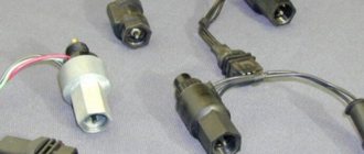
- We find the sensor and remove the wire block from it (If you have a 1.6-liter engine, then first unscrew the two fastenings of the throttle assembly to the receiver and move the throttle assembly from the end of the receiver by 1 cm).
- First, let's check the sensor circuit to see if the voltage is suitable for the sensor. We take a voltmeter and connect the negative block to ground (to the engine), plus connect it to the block of wires at terminal A and terminal D (the terminals are marked on the block). Turn on the ignition and look at the tester readings: the voltage should be at least 12 volts. If it is less, the battery is probably low. If there is no power, then the power circuit or the ECU is faulty.
- Turn off the ignition.
- Having checked the sensor circuit, we begin to check the sensor itself.
We connect the tester terminals to terminals A and B, then C and D - the resistance should be around 53 Ohms. Next, we measure the resistance in the following pairs: A and C, B and D. The resistance in these pairs should be infinitely large. If your sensor readings are different, it is recommended to replace the sensor. Before replacing the sensor, try cleaning (How to clean the IAC?) and repairing (How to repair the IAC?) it. Perhaps you will save extra money.
There is another way to check: to do this, completely remove the sensor by unscrewing two screws. Having pulled out the sensor, connect the block to it and place your finger on the tip of the sensor needle without making any effort. Theoretically, a working sensor at the moment the ignition is turned off fully extends its needle. Therefore, when you turn on the ignition, you should feel a slight push on your finger. If this does not happen, then the sensor is not working.
We check the idle speed sensor on a VAZ-2114 with our own hands: signs of a malfunction
If the idle speed of the car begins to “float”, and its operation as a whole has become unstable, then first of all you should check the idle speed sensor. In this article we will tell you in detail about this, and also tell you how to approach the issue of choosing this sensor.
Video with an overview of the main malfunctions of the idle speed sensor (+ replacement)
Main symptoms of a malfunction
Among all engine problems, “floating” idle speed is especially noticeable, and they manifest themselves in the following:
- The engine stalls when changing gears.
- The engine speed either rises sharply or drops to a minimum.
- The revolutions drop sharply at the moment of stopping with the engine running (at the moment of stopping at a traffic light - approx.).
If such symptoms are present, the idle speed sensor is usually faulty. However, before you start repairing it, you need to understand what it looks like and where it is located.
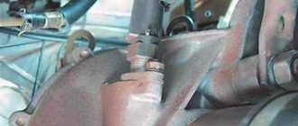
Sensor location on the engine
The sensor that regulates idle speed on a VAZ-2114 is usually fixed with two bolts next to the throttle assembly. It is easy to recognize by the presence of a power supply and its specific shape.
Idle speed sensor location
Now that we have figured out its location, we can begin diagnostics and, if necessary, repairs.
Troubleshooting
The difficulty in diagnosing the idle speed sensor lies in the fact that its problems will not be shown by the on-board computer, and its functionality can only be checked manually. The same cannot be said about the throttle position sensor, because they have the same symptoms of malfunctions, and the most ordinary on-board computer can identify the latter.
Checking the sensor circuit
- Before you start checking the sensor, make sure that the multimeter is working and ready for use.
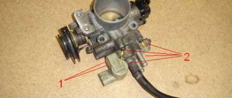
The idle speed sensor and its “wires” are below the throttle sensor. The throttle sensor is marked with an arrow. The block has been removed from the idle speed sensor.
Please note that on cars equipped with a 1.6-liter engine, it is necessary to remove the throttle assembly mount and move it away from the receiver itself by about a couple of centimeters.
Take a multimeter
- Then, on the multimeter, set the “voltmeter” test mode.
- We connect the black probe to ground, and fix the red one to the terminals of block A - D.
This is what the pin layout looks like on the IAC power supply block.
If after checking it is determined that the circuit is working properly, then you can proceed directly to the sensor.
Checking the idle speed sensor
When testing the sensor itself, you must connect the sensor to resistance test mode as follows:
- Regardless of the polarity, we connect the probes first to terminals A and B , and then C and D. If the sensor is working, then the values should be about 53 Ohms.
The values are normal.
If the test readings were abnormal, you can try to clean it with carburetor cleaner, or purchase a new one.
Which sensor should you choose?
In order to correctly approach the selection of an idle speed sensor for a VAZ-2114, you should know that the last two digits on the sensor article number have a special meaning. Because if the article number of the old one ended with “ 01 04 will be replaced , then there will be no sense in this, because it simply will not work properly.
Let's sum it up
As you can see, the idle speed sensor is an important and critical part in the ECM of a car engine. It is important to understand that the IAC is an electromechanical solution, that is, problems can arise in the electrical or mechanical parts.
We also recommend reading the article about what ELM327 is, what features the ELM327 scanner has, how this solution works and what functionality is available. From this article you will learn about the advantages of the ELM327 scanner, as well as what to look for when choosing this device before purchasing.
In this case, it is important that the sensor works correctly, that power is supplied to it, and that the ECU commands are carried out by the regulator accurately and in a timely manner. For this reason, it is necessary to check the electrical circuits, contacts and connectors, as well as the quality of operation of the regulator needle itself and other sensor elements.
Signs of a malfunction of the px on a VAZ 2114
The energy generated by the engine that drives the car is the result of instantaneous combustion of fuel. The required components of the combustion process are fuel (gasoline, gas, diesel fuel) and an oxidizer (oxygen from the air). A car engine will function normally if a balanced supply is provided.
Modern cars are controlled by a computer unit containing information about the supply of a fuel cocktail for different modes of engine operation. Experienced auto mechanics know how to create and program a table that determines fuel supply rates. Control is carried out by special sensors. The article examines issues related to one of them - the idle speed controller, signs of malfunctions of the VAZ 2114 idle speed controller.
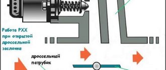
Purpose, device, operating principle of pxx
The idle speed sensor functionally plays the role of a stabilizer, an automatic engine speed controller in modes without traction (in neutral gear, when shifting gears).
The mass flow sensor analyzes the amount of incoming air and transmits information to the electronic control unit, which dispenses the required volume of fuel through the nozzles. The crankshaft position sensor provides the number of revolutions. The electronic unit processes the message and generates control signals for the idle speed controller. The increase in revolutions of a cold engine occurs due to IAC. The engine is warming up. Starting movement (not recommended) without raising the temperature to normal is possible due to the participation of this regulator.
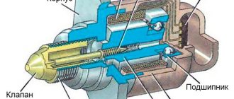
What does the pxx sensor on the VAZ 2114 consist of: 1 - valve; 2 — regulator body; 3 - stator winding; 4 — lead screw; 5 — plug terminal of the stator winding; 6 — ball bearing; 7 — stator winding housing; 8 - rotor; 9 - spring
The adjustment device is made in the form of a cylinder with two mounting ears. A spring-loaded conical needle is built into one end. Inside the housing there is a DC stepper motor containing two windings. Supplying control signals to the first circuit extends the conical needle, and retracts it to the second circuit. There is a detachable block on the side surface.
The device is located on the throttle body body, under the air duct hoses. Adjacent to the throttle position sensor.
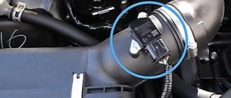
Where is the pxx on the VAZ 2114
If you don’t know where the pxx sensor is located on a VAZ 2114, then I hasten to describe the situation to you in the photo below.
Where is the pxx on the VAZ 2114
Signs of malfunctions of the VAZ 2114 px
Manufacturers of the VAZ 2114 did not provide diagnostics for the idle air regulator.
The on-board display will not display a message indicating an error in the operation of this mechanism. Inscriptions about low and high speeds do not guarantee breakdown of the IAC. The driver may notice changes in engine operation and suspect a malfunction based on indirect signs. The following symptoms are usually called:
- the engine suddenly “stalls” at idle;
- idle speed “floats” (randomly increases or decreases);
- when starting a cold engine, it is not possible to increase the speed;
- at the moment of changing gear, switching to “neutral” gear.
Such signs are caused by the unstable functioning of several sensors that take a direct or indirect part in preparing the fuel mixture (for example, a throttle position sensor).
Checking the RXX multimeter on a VAZ 2114
If you have a question about how to check the pxx multimeter on a VAZ 2114 car, then you have come to the right place. You need to take a multimeter and take several measurements; see the photo for what conclusions you need to check.
Checking the RXX multimeter on a VAZ 2114
Replacing pxx on a VAZ 2114
Replacing pxx requires preliminary preparation, eliminating possible surprises.
To replace pxx you need:
- perform a preparatory inspection,
- determine the essence of the problem,
- explore possible repair methods,
- stock up on the required spare parts, tools, and consumables.
Required Tools
To work you will need:
- working regulator;
- Phillips screwdriver;
- M13 head, ratchet driver;
- can of VD-40;
- rags;
- liquid for flushing carburetors;
- multifunctional measuring device;
- source of air flow (compressor, industrial hair dryer, special spray can).
Repair procedure for idle speed sensor
Typically, repair work is carried out in several ways. The reasons for the differences may be the vehicle’s equipment, level of training, style, habits of the mechanic, unforeseen breakdowns that occur along the way.
Changing the sensor can be done in two ways:
- with disconnection of preparation elements, air supply,
- without detailed disassembly.
Below we will consider the second option, which includes a minimum number of technological operations. If it is not possible to provide convenient access to the dismantling site, there will be an additional need to service, replace, or clean other adjacent parts, it is worth using the first method.
Step-by-step instructions for replacing the idle speed sensor on a VAZ 2114
- Raise and secure the hood.
- Turn off the power to the car - loosen and remove the negative terminal of the battery.
- Remove the engine casing.
- Carry out an external inspection of the fastening hardware, if necessary, clean it, treat it with a penetrating agent, and wait for the rust to break down.
- Unscrew the nuts securing the throttle assembly.
- Remove the remote control from the studs and carefully move it slightly to the side, freeing access.
- Disconnect the connector from the IAC block.
- Use a screwdriver to unscrew the screws and pull out the idle air control. There are cases of rigid fixation of mounting screws (cross-shaped grooves are painted over and drilled). This option will require dismantling the entire assembly, followed by continued disassembly on a table or workbench.
- Inspect the sensor. Check the windings with a tester to make sure there is a malfunction. Replacing a working device with a new one will not bring success. We'll have to look for another culprit for the car's unstable behavior.
- The wires of the first winding go to contacts A, B of the connector block, the second - C, D. The normal resistance AB (CD) is 53 Ohms. There should be no electrical communication between the two circuits (AC) - the device will show infinity.
- The serviceability of the device will raise suspicions about the integrity of the wiring. With the ignition on, measure the supplied voltage at the cable connector suitable for the IAC. The value should be at least 12V. Absence is a sign of a wire break or a problem with the control unit. Understatement - the need to charge the battery.
- Clean, rinse with carburetor fluid, wipe the assembly seat. Dry with air flow - no moisture should get inside the regulator.
- The surface of the cone should be flat, smooth, excluding bumps, sagging, and dirt. Otherwise, the calibration hole in the housing will not close tightly, and the fuel mixture will receive excess air.
Attention! On the new sensor, the spring-loaded needle can be extended to its full length. Before installation, the needle should extend to a distance of no more than 23 mm from the edge of the housing.
Trying to push the needle in manually is strictly prohibited. Such actions will cause the mechanism to malfunction. It is logical to use a special stand at a service station. Fans of radio engineering and electronics will be able to independently assemble an electronic device that supplies step control pulses to the sensor windings, extending and retracting the needle. You should first test the assembled device on an old sensor.
- Lubricate the O-ring on the device body with engine oil (for example, using a dipstick).
- Insert the working sensor into the seat.
- Reassemble in reverse order, lubricating the threaded connections.
- Reinstall the battery terminal and tighten it.
- Turn on the car's power with the ignition key. Wait 5 seconds. The on-board electronic control system will calibrate the needle extension.
- Start the engine and let it run without pressing the gas pedal. Observe the instrument arrow on the panel. As the engine warms up, the speed changes smoothly, without jerking.
- A negative result indicates the presence of an arc fault.
- The physical performance of components and mechanisms leads to the need for computer diagnostics, settings, and programming of engine operating modes.
Step-by-step replacement procedure
The replacement procedure is carried out in almost the same way as cleaning the device, but there are certain nuances:
- The battery is disconnected to prevent a short in the wiring.
- The plug with the electrical circuit is disconnected from the control device. If the car is equipped with an injection power unit, then to disconnect the connector you need to press on the plastic fastener.
- The bolts are unscrewed. As when cleaning, first unscrew the left fastener, and then the right one. The failed regulatory device is being dismantled.
- The surface on which the sealing element is mounted is also cleaned. The latter is checked for defects - abrasions, cracks, etc. If they are present, the sealing gum is replaced with a new one. Before installation, the seal is treated with engine fluid, after which it is mounted on the throttle seat.
- The controller is installed, a connector with wires for its power supply is connected. A wire is connected to the battery.
- After installation, a calibration procedure is performed. The microprocessor module must perform this independently; an electronic relay is used for this. To calibrate the new sensor, the ignition is turned on for a few minutes and then turned off. If the actions performed helped and the speed no longer floats, but remains at the same level, then the replacement procedure can be considered complete.
What do you need to know when replacing the IAC?
To change and install a controller that allows you to regulate idle speed, you need to pay attention to the position of the rod. It must not be allowed to be pushed forward too much. This can happen if the device is connected to the block and the ignition is activated before installation. It is not allowed to push the rod in by hand.
If the valve is installed with the needle extended and the retaining screws are tightened, damage to the unit may occur due to shearing of the worm gear. It is impossible to repair such a sensor. Depending on the vehicle model, after installing a new regulator, it may need to be calibrated. In some cars, this procedure is carried out using special equipment or a stand.
On VAZ cars, calibration is performed as follows:
- A terminal is connected to the negative output of the battery.
- The key is turned in the lock to turn on the ignition for ten seconds. There is no need to start the power unit.
- The ignition is turned off.
Learning to distinguish a fake from an original
Today, many people complain about the abundance of counterfeit products on the auto parts market.
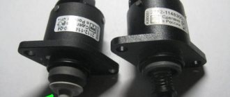
If we talk specifically about the XX regulator for the VAZ 2110, then there are several key signs by which a fake can be distinguished from the original. Be guided by these data so as not to accidentally install a device of dubious quality and origin on your car.
Fake and original
- On fakes, the black body made of metal is 1 millimeter shorter than the real part.
- In the case of the fake, the three white rivets on the case have no heads. They must be present in the original. And the diameter of the caps is 3 millimeters.
- On fakes, the spring is made in white and has more frequent winding. In the original, the coiling is less frequent, and the spring itself is black.
- Pay attention to the rubber ring of the regulator. On fakes it is black and thin, but in the case of a real part, a reddish tint is noticeable. Plus the thickness is greater.
- Take a closer look at the tip. In fakes it is darker compared to the original spare part.
- There are no markings on the counterfeit packaging; the boxes are noticeably different in appearance.
- The original yellow sticker located on the case must have an outer frame. Manufacturers of counterfeits apparently forgot about it.
As you can see, recognizing a fake is not difficult. You just need to be more attentive to details.
The difference is in the boxes
Idle speed sensor for VAZ 2114
Many car owners unwittingly became acquainted with the mysteries of the idle speed sensor on their VAZ 2114. The real name of the controller is the idle speed controller (IAC). This is a complex unit in the system of injection engines, which is commanded by electronics (among motorists, “brains”). In case of incidents with IAC, the engine begins to “act up”, causing discomfort and troubles to the driver. Next, we will tell you where the idle speed sensor of the VAZ 2114 is installed, what signs indicate its error, and how to change the IAC yourself.
Device
Modern automakers use 3 types of idle speed sensor: solenoid, rotary and stepper. For VAZ 2114–2115 the latter type is used. IAC is a stepper mini-electric motor that opens/closes the air duct of the intake manifold of the internal combustion engine, thereby regulating the speed (similar to a bolt on a carburetor).
The IAC design has a ring magnet, a lead screw (needle) and 2 windings. When voltage is applied to the magnet and windings, an electromagnetic field appears. As a result, the lead rotor begins to rotate, thereby driving the lead screw through the worm gear. Depending on the position of the rotor, the needle valve is able to control the opening/closing of the air duct of the intake manifold.
For reference. What is a step? This is the distance between the conical shut-off valve (IAC tip) and the intake manifold. It is measured by the number of full rotations of the rotor.
Principle of operation
The balanced relationship of the injection engine components is adjusted by the electronic unit (ECU). When you turn the ignition key on a VAZ 2114, the IAC needle closes the air hole on the manifold. After the engine starts, the ECU calculates the required number of steps and sets the regulator needle to the working position, slightly opening the air channel to lean the mixture.
Taking into account the engine temperature and the position of the needle, the ECU regulates the further operation of the internal combustion engine. On a cooled VAZ-2114 engine, the idle speed sensor will again close the air valve, thereby enriching the mixture and increasing the speed.
For reference! The number of steps is determined by the software (firmware). For example, on a hot engine with a “January 5.1” controller it is usually 110 shg. and at Bosch - 50 shg. Maximum stroke 250 shg.
Fault marker and cause
It is very difficult to calculate the breakdown of the IAC. The VAZ on-board computer is primitive and cannot always detect a failure in the system. The owners do diagnostics several times, but there are no errors on the scanner. At the same time, the car works poorly, and the “Check Engine” is stubbornly silent. The owners of the “four” had no choice but to use samples and replace spare parts to determine the cause. Thanks to them, the main symptoms of a malfunction of the idle speed sensor are now known:
- poor starting of the internal combustion engine, especially in winter;
- floating engine speed when hot, in the range of 850–1100;
- the engine freezes if you put the gear in neutral or release the gas;
- The firmware reduces the speed to 800–900 on a cold internal combustion engine (less than 40 °C), without waiting for it to fully warm up.
The main reason for DX failure is natural wear and tear. As a rule, wear appears in the lead screw and rotor. Due to backlash, the ECU cannot accurately adjust the needle pitch. Sometimes the winding burns out as a result of a short circuit. But the most common reason is contamination of the cone valve.
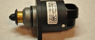
Which to choose
If symptoms or diagnostics confirm that the idle air regulator on your VAZ 2114 is defective, then all you have to do is go to the store for a new sensor. Independent auto industry experts and service workshop specialists recommend purchasing an original IAC. Its number is 2112-1148300-02 (sometimes ending: 01, 02, 04). If there is no factory part, then you can replace it with a worthy analogue.
Table 1. Price of idle speed sensor on VAZ 2114
| Manufacturer | Number | Amount, rub. |
| AvtoVAZ | 21120114830081 | 730 |
| KRAFT | KT104900 | 510 |
| MANOVER | MR21121148 | 450 |
In addition to the above, the products of the manufacturers “Omega” and “KZTA” have proven themselves well.
How to check IAC
There are a lot of counterfeits on the spare parts market. Popular parts are often counterfeited in poor quality. Even some car owners have complaints about Omega, although the majority of VAZ users praise this manufacturer’s IAC. Sometimes you come across outright dummies. Therefore, service workshop specialists are recommended to organize a check of the idle speed sensor before installation on the VAZ 2114.
Self-diagnosis will require a multimeter, which should be switched to an ohmmeter. The IAC has two windings, and there are four outputs on the block: A, B, C, D. First we test A and B (first winding), then C and D (second winding). For model 2112-1148300-02 the natural resistance is 51 (±2) Ohms, and for 2112-1148300-01 - 53 (±5) Ohms. If the parameters on the multimeter tend to infinity, then there is probably an open circuit in the winding circuit.
Attention! The needle on the new regulator should stick out from the body no more than 23 mm, that is, be in a half-closed position. If it protrudes strongly from the body of the regulator, then during installation the splines of the lead screw can be damaged. Car service specialists will help you return the needle to the lower position.
Replacement
Before you begin replacing the idle air control on a VAZ 2114, you need to prepare. It is better to carry out repairs in a well-lit garage, since on a 1.6 engine (16 valves) you will have to “unfasten” the throttle assembly. On 8-valve engines, craftsmen do without dismantling this mechanism. But sometimes the screws cannot be unscrewed (especially the lower one), so you have to disconnect the fuel supply unit from the manifold, and at the same time clean the dirty channels.
To replace the IAC yourself, you will need a simple set of tools: a durable medium-sized Phillips screwdriver, a 13 mm wrench (head), WD-40 lubricant, aerosol carburetor cleaner and a rag. There is a gasket between the throttle body and the intake manifold. Quite often it is in poor condition due to prolonged use. It’s better to buy a new one in advance (price 30–40 rubles). Step-by-step instructions for replacing the IAC VAZ 2114 (8–16 valves) look like this:
- Secure the car with the handbrake.
- Remove the negative terminal from the battery.
- Remove the engine protective screen (for 1.6).
- Loosen the clamps on the crankcase exhaust pipe and the corrugated pipe.
- Disconnect the corrugation from the throttle assembly.
- Remove the upper idle crankcase ventilation pipe.
- Remove the throttle cable.
- Unscrew the 2 nuts of the throttle assembly and remove it from the studs.
- On the left, below, find the location of the IAC.
- Unplug the power plug from the sensor.
- Unscrew the 2 screws of the regulator using a Phillips screwdriver.
- Clean the assembly from carbon deposits and dirt using carburetor cleaner.
- Coat the rubber ring of the regulator with machine oil.
- Install the IAC into the throttle mechanism.
- Collect everything in reverse chronology.
Attention! Once you have finished replacing the idle speed sensor, do not try to start the car. First you just need to turn on the ignition and wait 10–15 seconds. The system will automatically adjust the IAC to the operating position. Then it is recommended to repeat the operation 3-4 times (masters call this “registration”). Only then can you start the car, warm up the engine and evaluate its performance.
Conclusion
The idle speed sensor for VAZ 2114–2115 (correctly IAC) is an electric micromotor with a stepper mechanism. Over time, its internal parts (lead screw and rotor) wear out, so the fuel mixture is incorrect, as a result of which the engine begins to run unbalanced. At the same time, the electronic unit does not always see a failure in the system and does not indicate a malfunction with the Check Engine icon. Therefore, owners cannot immediately determine the source of the problem. But it is possible to identify a failure based on a number of signs. To replace it, it is better to use the original idle air regulator, and you can do the repair yourself.
Diagnostics, repair and replacement of idle air control
To check and replace the regulator itself, you will need to dismantle the throttle assembly and disconnect the device from it. The following tools and resources will be needed:
- screwdriver with Phillips bit;
- slotted screwdriver;
- round nose pliers;
- socket wrench or socket 13;
- multimeter with the ability to measure resistance;
- calipers (you can use a ruler);
- clean dry cloth;
- coolant for topping up (maximum 500 ml).
Dismantling the throttle assembly and removing the IAC
To remove the throttle assembly, you must:
- Raise the hood and disconnect the negative cable from the battery.
- Using a slotted screwdriver, hook the end of the throttle cable and remove it from the gas pedal pin.
- On the throttle block, use round pliers to disconnect the clamp on the throttle valve drive sector.
The fastener is detached using pliers or a screwdriver - Turn the sector counterclockwise and disconnect the cable end from it.
To disconnect the tip, you need to turn the drive sector counterclockwise - Remove the plastic cap from the cable end.
- Using two 13mm wrenches, loosen the cable fastening on the bracket.
To loosen the cable, you need to loosen both nuts - Pull the cable out of the bracket slot.
To remove the cable, it must be removed from the bracket slot - Disconnect the wire connectors from the IAC connectors and the throttle position sensor.
- Using a screwdriver with a cross-shaped bit or pliers (depending on the type of clamps), loosen the clamps on the coolant inlet and outlet fittings.
Remove the clamps. In this case, a small amount of liquid may leak out. Wipe off any spills with a dry, clean cloth. The clamps can be loosened with a screwdriver or pliers (round pliers) - In the same way, loosen the clamp and remove the hose from the crankcase ventilation fitting.
The crankcase ventilation fitting is located between the coolant inlet and outlet fittings - Using a Phillips-head screwdriver, loosen the clamp on the air supply pipe.
Remove the pipe from the throttle body. The air pipe is fixed with a worm clamp - Similarly, loosen the clamp and remove the hose for removing fuel vapors from the fitting on the throttle assembly.
To remove the fuel vapor exhaust hose, you need to loosen the clamp - Using a socket wrench or a 13mm socket, unscrew the nuts (2 pcs) securing the throttle assembly to the intake manifold.
The throttle assembly is attached to the manifold using two studs with nuts - Remove the throttle body along with the sealing gasket from the manifold studs.
A sealing gasket is installed between the throttle assembly and the manifold - Remove the plastic bushing that defines the air flow configuration from the manifold.
The plastic sleeve sets the air flow configuration inside the manifold - Using a Phillips-head screwdriver, remove the two screws securing the regulator to the throttle body.
The regulator is attached to the throttle body with two screws - Carefully remove the regulator, being careful not to damage the rubber O-ring.
A rubber sealing ring is installed at the junction of the IAC with the throttle assembly
Video: removing and cleaning the throttle assembly on a VAZ 2107
Finding and checking the idle speed control on a VAZ 2114: detailed instructions
The first production Zhiguli cars were equipped with Weber carburetors, which only had a regulator for the quantity and quality of the fuel mixture. After further modernization of this device, solenoid valves appeared on the third, sixth models and Niva. The fifth and sixth Zhiguli models have already received a forced idle economizer system. The family of cars with front-wheel drive and injection engines received an idle speed controller.
The idle air control on VAZ 2114, 2113 and 2115 looks exactly like this
ITS PURPOSE IN THE CAR POWER SYSTEM
This device, an essential device for saving fuel, has several common names. It is called a valve, a sensor, and also a regulator for adjusting the idle speed. The operating principle is approximately the same for all devices. It consists of changing the flow area of the inlet channel for the air mixture into the receiving tract of the engine.
If on previous models the operation of the device consisted only of opening or closing the air channel, then in this model, as well as for the VAZ 2113 and VAZ 2115, the operating principle is slightly changed. It is a stepper motor with a cone-shaped needle. The electronic engine control unit reads the readings of various sensors that control various engine systems, and in accordance with their readings, turns on a device whose “step” range is approximately 250 steps.
WHERE TO FIND IT ON THE ENGINE
If someone does not know where the idle speed sensor is located, then we will tell you about its location. These devices are installed on the throttle bodies, fastened using two screws. There is also such a method of fastening as “landing” on the varnish. But it has not become widespread due to the complexity of such work. In the picture the arrow indicates the place where the pxx is installed on the VAZ 2114.
HOW THIS DEVICE WORKS
When the ignition is turned on, the rod completely blocks the air channel and returns to its original position. At the moment of his return, the controller counts his steps. Their number may vary, but depends mainly on the controller firmware. When the engine warms up, it opens the idle valve one gap, and while the warm engine is running, it releases a portion of the air mixture depending on the need.
Signals for determining the required amount of air come from the mass air flow sensor. The controller reads and determines its need in order to issue a control pulse to the pxx. The engine crankshaft position sensor and its signals also participate in the control; the position of the sensor’s conical needle is adjusted through the control unit.
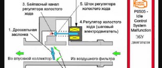
IAC diagram
WHAT ARE THE SIGNS OF ITS MALFUNCTION?
While such sensors are not yet equipped with diagnostic systems, the driver will not see a signal on the display about its malfunction. For now, it is possible to judge the problems with it or check the RX on the VAZ 2114 only by indirect signs, which are quite sufficient to make a correct diagnosis. These signs include:
- Unexpected stops when idling;
- Floating speeds are observed when operating at idle speed;
- It is impossible to achieve an increase in speed when starting a cold engine;
- When the speed is turned off, the motor stops.
I would like to warn car owners that similar signs of malfunctions occur in other sensors, but the controller reacts to some of them and displays an error code on the display.
HOW CAN YOU CHECK ITS OPERATION?
It is best to check performance using instruments. Let's look at how to check the idle speed sensor of a VAZ 2114. It’s good if you can find the simplest multimeter for these purposes, it will be quite enough. To conduct an “instrumental check” you must:
- With the ignition off, remove the connector with wires from the sensor;
- The device is switched to voltage measurement mode and with the ignition on, check its presence on the connector wires;
- If voltage is present, the sensor is faulty, otherwise check the entire circuit from the sensor to the controller.
Checking the idle air regulator can be done without instruments. To do this, check the extension of the rod on the removed sensor with the wires connected when the ignition is turned on. If you lightly hold the cone needle with your finger and turn on the ignition, it should come out. Those owners who know the basics of radio engineering can assemble an pxx tester with their own hands, which can be used to test pxx with a stepper motor. Whoever is interested in such a device, its diagram will be below.
As can be seen from the diagram, the device is connected to the on-board network, and the second connector is connected directly to the sensor.
Now a few words about how to check the idle air control sensor using this device. To do this you need:
- Connect the device to the battery, and the second connector to the sensor terminals;
- When turned on, it retracts all 250 steps, then it extends the rod with the needle about 70 steps;
- Pressing the buttons k1 and k2 will extend the conical needle and vice versa, retract it;
- A comprehensive check of the idle speed sensor will be carried out if you turn on both buttons at the same time and hold them on for a little more than 3 seconds. The device will begin to periodically move in and out the rod with the conical needle;
- A variable resistor can be used to change the speed of the test operation.
IS THIS DEVICE REPAIRABLE?
There is no need to rush to purchase a new sensor because in some cases it is possible to repair the idle speed sensor. Very often, especially when low-quality fuel is used, or the engine life is close to a major overhaul, coking of the rod with the conical needle in the device body occurs. What do they do in such cases?
Carburetor cleaning fluid can come to the rescue. A cotton swab dipped in this liquid cleans all contacts well. After this, the cone needle rod is cleaned. Usually after these steps it starts working.
If there is a break in the wiring inside the sensor, then in some cases this can be fixed. You need to carefully disassemble the body of the device and carefully inspect its internal contents. A broken connection wire can be corrected if it is possible to solder it to the connection point. If everything works out, then the soldering area needs to be covered with a layer of varnish to protect it from corrosion. If a wire breaks inside the stepper motor winding, it is almost impossible to fix it. In this case, the sensor is simply changed.
Description of the regulator
The idle speed control is one of the most important sensors in a car's injection system. It is he who corrects stable idle speed. The regulator is involved in engine operation only at idle.
The IAC is a cylindrical DC electric motor with a worm gear. A shut-off valve is installed on the worm shaft, which, when forming the air-fuel mixture, blocks the flow of air into the throttle valve.
The operation of the IAC is only mechanical by blocking the incoming air channel in the throttle valve. That is, when there is a need for increased speed at idle, the regulator closes the air channel, thereby forming a fuel mixture with a large amount of fuel, as a result of which the engine speed becomes higher.