How to Remove the Crankshaft Pulley Yamz 236
Crankshaft pulley YaMZ 236-1005061-B
Crankshaft pulley 2-thread, si. arr.
Spare parts for tractors:
crankshaft pulley (3 thread, st. st.)
pulley D21-1308157 crankshaft (1 tutorial)
Crankshaft pulley D37-1308157 (2 threads)
Ltd. "TD PROTON" sells YaMZ engines of its own production
The existing crankshafts were restored (polished, tested for cracks, hardness and mileage) by the Minsk Motor Plant for the MTZ 1221 tractor, Amkodor loader, MAZ truck.
Delivery of products to Russia and the CIS by transport companies DPD and PEC from Smolensk, Russian Federation or DPD from Vitebsk, Belarus.
We guarantee quality and an individual approach to cooperation.
New crankshaft D-260 (75,000)
Crank shaft D-260 N1 BU (45000)
shaft D-260 H2 polished BU (40,000)
The crankshaft D-260 N2 is not ground B.U. (35,000)
Crankshaft D-260 P1 polished B.U. (30000)
Crankshaft D-260 R1, not ground B.U. (25000)
as a way to remove a pulley, crankshaft, etc. make yourself a simple shooter
Removing, removing and checking the crankshaft, YaMZ
-238 after speeding. Winter outdoors
Dismantling a clogged Yamza-238 in winter on the street of the Ural timber truck
Water constantly flowed into the crankcase, we decided to disassemble the NMZ
-238. DON 1500 B combine harvester.
Crank shaft D-260 P2 polished B.U. (25000)
Crankshaft 240-1005015 (used) Uralsk
240-1005131 pulley crankshaft D243
Crankshaft (crankshaft) of the YaMZ-240 engine, standard size, without liners, removed from the engine. Good condition. At a price that has not yet been determined, we are waiting for your proposals. Deal.
Engine crankshafts
D-241L, D242/242L, D-243/243L, D-244, D-245, D-245.12S, D-245.7, D-245.7E2, D-245.9, D-245.9E2).
D-241l, D-242, D-243, D-244
2 245,9-1005010 (245,9-1005015)
These types of products are used in the following types of machines and mechanisms
Prompostavka LLC is ready to offer mutually beneficial cooperation for you!
We want to offer a wide range of applications. parts MTZ, DT-75, T-40, T-25, T-16, YuMZ, T-130/170, MAZ, YaMZ
Our company is constantly expanding the range of products sold.
We guarantee fulfillment of your order for the spare parts you ordered, as well as fast delivery!
We will be happy to answer your questions and process your applications seven days a week, from 9:00 to 23:00! Delivery to transport companies is free, regardless of the order amount, flexible system of discounts, shipment from warehouse.
We hope for long-term and mutually beneficial cooperation!
Source
Engines YaMZ-236 and YaMZ-238: Disassembly and assembly alone
When repairing a YaMZ engine, there are not always convenient conditions and lifting mechanisms are not always at hand. Therefore, over time, a certain technique for disassembling the engine and its subsequent assembly was developed.
In addition, I can say that all the steps for assembling and disassembling the engine can be performed almost alone. It doesn’t sound very plausible, considering that the engine weighs 1000-1250 kg. But let’s not rush to conclusions, let’s try to figure it out.
Installing the engine at the disassembly site
When removing and installing the engine at the disassembly site, it is desirable that the base be strong (for example, asphalt or slabs). It’s better to lower it onto something soft for the first time (for example, an old cylinder) and on the left side unscrew the bolts holding the main bearing caps together.
Then, hook the slings or chuck over one head (at the front and rear eye bolts) and prepare an old cylinder liner or a piece of timber along the length of the liner.
It is better to lift the engine by the right head, and then lower it to the floor so that the opposite head rests on the manifold, and the block connector on the pallet rests on a vertically placed sleeve in the middle of the block. An inch board should be placed under the collector.
Pulley installation
Installing a keyed wheel consists of the following steps:
- Insert the segment or rectangular key into the groove provided on the motor shaft.
- Heat the new pulley to a temperature of 125-150°C, and then put the part on the axle.
- Install the drive element using a mandrel and a hammer until it stops.
- After the parts have cooled, the engine is installed in its original place, and then the belt is put on.
- Check the operation of the drive, replace the removed covers of the washing machine body.
When installing the drive on a spline shaft, it is necessary to apply thread locking agent to the surface of the axle. The pulley for the poly V-belt is placed on the shaft using a screw press or a vice; warping of the parts is not allowed. The element is installed on the shaft to its original state (the location of the end edge of the pulley must be marked on the shaft before removing the part). The applied sealant crystallizes within 12-24 hours (depending on the manufacturer); engine operation is allowed after the fixative has hardened.
The drum pulley is put on the shaft in a heated state; sealants are not used in the connection. The part is pressed onto the shaft until it stops by striking a wooden spacer with a hammer. Excessive force poses a risk of structural failure. Then the central bolt or nut is tightened, which is kept from spontaneous unscrewing by a thread lock or the bent edges of a steel washer (depending on the manufacturer of the washing machine).
Dismantling of YaMZ-236 and YaMZ-238 engines
We also remove the fine oil filter. Next, remove the clutch, flywheel and clutch cover. Now, you can start removing the pan, oil pump, and most importantly, don’t forget to remove the corner of the oil pipe screwed to the block.
After this, you can unscrew connecting rods 1, 2, 3, 4 and pull them out along with the pistons. To remove sleeves, it is better to use a special puller, and if you don’t have one, then a copper drift. If the sleeves go to scrap metal, then it is much easier to knock them out with an old axle shaft; it is especially convenient to do this with ZIL or KamAZ axle shafts.
The next step is to begin removing the engine crankshaft. To do this, unscrew the main bearing coupling bolts from the side of the right head, and then unscrew the main bearing caps from the bottom. We take out the lids, leaving the middle one in place. Next, turning the crankshaft sequentially, unscrew connecting rods 5, 6, 7, 8 and remove the connecting rod caps.
Since the block connector plane is in a vertical plane, we prepare a couple of bars and insert them under the crankshaft counterweights. Holding the crankshaft, remove the last middle crankshaft cover and carefully roll it out.
We take the jack, place it at an angle and rest it on the upper corner of the middle of the block connector, jack it up a little and pull out the sleeve from under the block. We lower the jack and if there is not enough movement, then we intercept and lower the block to the ground on the gasket.
Then, use a pry bar to lift it by the left head and place a block under the connector of the block with the head so that the board gasket between the collector and the asphalt comes out. Now we remove the left cylinder head, connecting rods with pistons 5, 6, 7, 8 and cylinder liners. That's it, the engine is disassembled.
Assembly of YaMZ-236 and YaMZ-238 engines
After disassembling the engine, we repair the parts, sharpen or change the crankshaft and piston if necessary, and begin assembly. To do this, we tilt the block onto the 5-8 cylinder, place an inch board under the studs, then place the jack on the edge of the block and lift it so that the sleeve can be placed again.
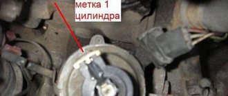
Then, we take the main liners and insert them into the block. Next, if you are alone, then roll the crankshaft into place using blocks and secure it with the middle main cap. We rotate the elbow so that the marks on the camshaft match and install the first yoke, not forgetting to lubricate the liners and bolts with oil.
Then, we put the last one in place and tighten all the others. It is better to tighten the radicals in two steps: the first time 20 kgm; the second, already thoroughly 43-47 kgm.
In order to tighten the radicals, I usually took a multi-faceted spanner and a pipe, and made a mark at 55 centimeters with a file. The wrench was alternately moved to the upper and lower bolts of the main bearings and, under its own weight, sequentially tightened the yoke, not forgetting to turn the shaft after each tightening of the bearing.
Afterword
When operating a MAZ vehicle, it is not uncommon to have to seriously strain yourself; many of us are faced with sciatica and similar diseases. Therefore, when you lift some parts, remember your health.
In my youth, I went to lift weights, I didn’t achieve great results, but I remembered the words of the coach. He said that if you want to be friends with the barbell, then train your legs. After all, the average person’s dead abs pull about 200 kg, so load your legs while keeping your back straight.
For reference, the YaMZ-238 engine head weighs about 90 kg, and the crankshaft 120 kg. Parts of domestic engines are not easy.
However, I had to remove the head from the YaMZ-238 engine many times alone: either you tear it off the gasket with a pry bar, or with the help of your legs, with a straight back and outstretched arms, you manage to lift it from the studs and move it onto the wheel.
I hope that such exercises were given to me without harm to my health. However, it is undoubtedly better to drag such parts together or using lifting mechanisms.
Source
Dismantling the YaMZ-236 engine; 238 MAZ vehicles
An engine removed from a vehicle for repair is disassembled completely or partially, depending on the nature of the damage.
Complete disassembly of the engine is carried out in three stages: partial disassembly, disassembly of the engine into components and parts, and disassembly of engine components into parts.
Disassembly of YaMZ-236 and YaMZ-238 engines is carried out taking into account design features.
Before disassembling, the engine is temporarily placed on a stand, protecting the sump from damage, and the clutch housing mounting bolts are unscrewed.
Remove the gearbox together with the clutch housing, supporting it from below so as not to damage the clutch driven discs or the drive shaft of the box, unscrew the bolts securing the clutch housing to the flywheel and remove the pressure plate with housing assembly.
The bolts must be unscrewed gradually, loosening one by one, since otherwise the last remaining bolts may be torn off by the force of the pressure springs.
Next you need to remove the driven disk.
For clutches YaMZ-238K, YaMZ-2Z8, YaMZ-236K, the middle drive and front driven discs should also be removed.
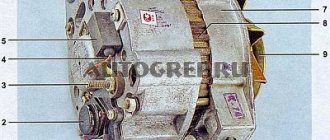
After this, it is necessary to unscrew and unscrew the two coupling bolts 2 (Fig. 1) securing the starter, remove the starter 3, the generator and the air brake compressor, unscrewing the bolts, remove the fan impeller 10 (Fig. 2), unscrew the rod 17 and remove the air filter 16, remove four side plugs 23 (see Fig. 1), two each on the right and left sides.
Having installed the engine on the stand (Fig. 3) and secured it with four clamps inserted into the holes of the water channels, it is necessary:
— remove the oil level indicator;
— loosen the screws of the coupling clamps, remove the bypass 14 (Fig. 2) and connecting 15 tubes of the water thermostats;
— remove the connecting pipe 15 (Fig. 1) of the intake manifolds and the mounting brackets for the high-pressure fuel pipes;
— disconnect pipes 12 and fuel outlet pipe 11, having first freed it from the clamp.
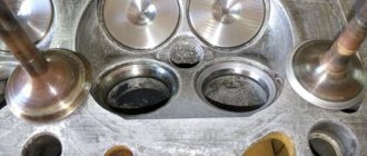
After removing the covers of 10 cylinder heads, you must:
— having disconnected the drainage tubes of the injectors, unscrew the nuts securing the injector brackets and remove the injectors 9
— remove rocker arms 18 with axles assemblies, remove push rods 5;
— remove the 8 cylinder heads and their gaskets.
Turning the engine on the stand with the flywheel housing down, remove the pan 27, the oil pump 28 with the differential valve 26 and tubes.
We unscrew the connecting rod bolts and remove the connecting rod caps, take out pistons 4 assembled with connecting rods 24.
We place the connecting rod caps on the corresponding connecting rods, guided by the marks, and screw them in with bolts.
Turn the engine to the working position and disconnect the low pressure pipes, remove the fine fuel filter 12 (Fig. 2);
— unscrew the nut securing the coupling half on the driven gear shaft of the fuel pump drive and remove coupling half 13 together with the coupling half washer and press the key out of shaft 9;
— remove the coarse and centrifugal oil filters (CMO) and flywheel 22.
To remove the flywheel, we use two cranks 1 (Fig. 3), which we screw into special holes with an M12 x 1.75 thread until it stops in the crankshaft 2.
To avoid distortion of flywheel 3, we screw in the cranks at the same time.
Then, remove the flywheel housing 25 (Fig. 2), the sidewall of the oil pump pulley and the oil pump drive belt.
Having unscrewed the crankshaft pulley mounting bolt using a puller (Fig. 130), remove pulley 2 (Fig. 2) and remove the key from the crankshaft.
After this, remove the bracket 6 of the front engine mount and the top cover 11 of the block, the fan drive housing, the cover 4 of the distribution gears assembled with the water pump.
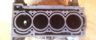
Having turned the engine on the stand with the crankcase facing up, you should:
— unscrew and unscrew the bolts securing the main bearing caps, remove the caps 26, remove the crankshaft 3 from the cylinder block 23, using a special suspension (Fig. 5), protecting the shaft journals from damage;
— remove the liners and thrust half-rings from the supports and main bearing caps, put the main bearing caps in their places, following the marks;
- Unscrew the bolts securing the thrust flange 5 (see Fig. 2) of the camshaft, first bending the lock washers to remove the camshaft 21 assembled with gears;
— press out the 20 pushers, starting from the rear axle, and remove the pushers 19 and the pusher spacer bushings.
Turning the engine on the stand with the crankcase down, remove the bolts securing the thrust flange of the driven gear of the fuel pump drive.
Main stages of work
As it may seem at first glance, the work ahead is not very difficult; the main thing is to understand what will have to be done.
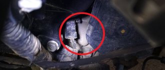
- First of all, we find access to the pulley so that we can access it with a key or ratchet.
- If the bolt cannot be unscrewed with a wrench, you can try to remove it using the starter.
- Alternatively, you can always use special removable devices.
Now about all this in more detail.
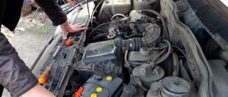
Pulley search
Obviously, your very first action is to find the location of the crankshaft pulley in the engine. As a rule, it is located on your right, less often on the driver's side. Sometimes it can be hidden in the lower front part of the engine.
You need to start looking for it by inspecting the place behind the generator. Most likely you will see something resembling a disk at the bottom of the engine compartment. This will be the part you are looking for.
Preparatory work for convenient access to the necessary components
You need to be prepared for the fact that, depending on the car model, you will have to remove the coolant reservoir, the air filter unit, possibly the radiator and almost always the wheel.
Quite often, such work has to be started by removing the right wheel. You also need to know the location of the ignition coil.
How to remove the crankshaft pulley bolt for starters
The main problem will be to fix the shaft, since its rotation coincides with the threads of the bolt.
On rear-wheel drive cars of the Lada family, the pulley is fixed with a nut (the element is known as a ratchet, due to the ledge for the crooked starter), on front-wheel drive cars with a bolt.
If you don’t have a special tool for removing a bolt in your arsenal, then this job will not be easy for you. The shaft will have to be locked using a fairly long wrench that rests on a hard floor. Head sizes, depending on the brand of vehicle, usually range from 14 to 38.
In some vehicle models, this function can be performed by screwing a bolt designed for this into a special socket. We disconnect the ignition wires or take out the fuse for the fuel pump so as not to accidentally start the engine. It is necessary to place special shoes, bars or any other objects under the wheels that will completely prevent the vehicle from moving.
We take all spectators, assistants and just friends to a safe zone. We ourselves send the gear knob to fourth speed and turn the ignition key with lightning speed. It didn't work the first time, let's try again. Until the bolt turns.
After a successful attempt, we go for the puller and get to work on the pulley itself. Unscrew it counterclockwise. If you are the happy owner of a Honda car, then there is a special ½-inch holder for you that will make your work much easier. It is available for purchase from many online stores.
It is not recommended to perform this operation with the ignition key on some Mazda family cars, since it will be quite difficult to put the unit back together. Also, under no circumstances allow the shaft to rotate in the direction opposite to rotation.
Removing the pulley using pullers
With the bolts removed, you can now remove the crankshaft pulley. To do this, remove the timing cover to give yourself complete freedom to do things like replace the timing belt or seals.
After removing the bolt, you can take on the pulley and this will not be easy. First of all, you will have to remove the belt. To do this, you need to loosen the generator locking bolt, then turn the tension bolt. The belt will loosen and you can remove it. You may find it uncomfortable to operate due to the power steering belt. Then we weaken him too.
The last step of the job is to find the bolt securing the pulley. You can almost always find it if you look under the car next to the right wheel. We go for a pneumatic impact wrench and remove the wheel.
An impact gun will be a great tool for removing a stubborn crankshaft pulley bolt. It has also been experimentally found that a torque wrench is a useful tool for securing it correctly.
All precautions must be taken before lifting and securing the front of your vehicle.
Next, a new stage awaits us - removing the pulley hub from the shaft. It is tightly fixed with a key. To do this, you need a set of inexpensive pullers.
Take the rod, screw it into the main part of the puller a few times and snap it into the end part so that it presses against it. The next step is to do the same on the other end so that it puts pressure on the crankshaft.
On a normal car you will probably notice 4 small threaded holes, which is an advantage as you can insert bolts into them. Once the puller assembly is ready, put it on, remove one bolt and nut and screw it into the small hole. After that, screw another bolt into the hole on the opposite side.
Now that you have both holes pressed tightly, take the socket and secure it using a wrench and keep turning it until it comes off.
Slippage can cause misalignment between the center hub and the drive ring. As a result, the crankshaft pulley will vibrate. This can lead to premature wear.
Never use a jaw puller to remove your vehicle's crankshaft pulley. Using this tool will only rupture the rubber o-ring through the tension of the outer edge of the crankshaft pulley. Use only the recommended pulley removal tool to remove pressure concentrated on the rubber ring.
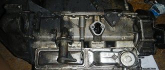
How to remove the crankshaft pulley Yamz 236
To balance the engine and unload the main bearings from the inertial forces of the moving masses of the pistons and connecting rods and unbalanced centrifugal forces, counterweights are installed on the cheeks of the crankshaft, with which the shaft is balanced. In addition, the balancing system includes two remote masses, one of which is made in the form of a recess on the flywheel mounted on the rear end of the crankshaft, the other is a counterweight mounted on the front end of the crankshaft.
Axial fixation of the shaft is carried out by four bronze half-rings installed in the grooves of the rear main support. To prevent rotation, the lower half rings fit into pins pressed into the rear main bearing cover with their grooves.
The toe and shank of the crankshaft are sealed with rubber self-tightening cuffs.
A crankshaft gear and a front counterweight are pressed onto the front end of the crankshaft, secured with a nut with a tightening torque of 176.4 - 294 Nm (18 - 30 kgf m).
The crankshaft of the YaMZ-238BE2, YaMZ-238DE2 engines has a cone at the front end. A hub is installed on the cone, on which a liquid vibration damper and a pulley are attached. When repairing an engine, it should be remembered that impacts and dents on the torsional vibration damper will disable it, which will inevitably lead to breakage of the crankshaft. The extinguisher should be stored and transported only in a special container in an upright position.
The YaMZ-238BE, YaMZ-238DE engines are equipped with a crankshaft 238BE-1005009 (marking 238N-1005015-U), and the YaMZ-238BE2, YaMZ-238DE2 engines are equipped with a crankshaft 238DK-1005009-30 (marking 238DK-100501 5-30) .
The crankshaft in the forging is marked on the 5th cheek.
The crankshaft journals can be of two nominal sizes and therefore the following marking options and the use of corresponding liners are possible.
Note: The letters “DK”, “N”, “U”, “Sh”, “K” and the numbers “30”, “1” are stamped when marking using the impact method.
The flywheel is cast from gray cast iron. The flywheel is marked in a recess on the non-working surface of the casting. The following types of flywheels can be installed on engines:
− 238-1005115-K (for a ring gear with a module of 4.25);
− 238-1005115-N (for a ring gear with a module of 3.75).
These flywheels assembled with toothed rims are not interchangeable with each other.
Flywheel 238-1005115-K (for a ring gear with a 4.25 module) is installed with a starter model 2501.3708-01, and flywheel 238-1005115-N (for a ring gear with a 3.75 module) is installed with a starter model 2501.3708-21.
The flywheel is bolted to the crankshaft. A high-hardness steel plate is installed under the bolts (one for all bolts). The absence of self-loosening of the bolts is ensured by a tightening torque of 235-255 N m (24-26 kgf m). To accurately fix the flywheel relative to the crankshaft journals, two pins are used; in this case, the holes marked on the flywheel and on the plate must coincide with the offset pin on the crankshaft. The offset pin is located in the plane of the first crank. The marking on the plate in the form of a dot should be on the outside.
Twelve radial holes in the flywheel are designed to rotate the crankshaft during engine adjustments.
Access to the holes is possible with the flywheel housing lower hatch cover removed. Rice.
3 — Steel connecting rod, I-section, with an oblique connector of the lower head. The connecting rod is finally processed together with the cap, so the connecting rod caps are not interchangeable. The cylinder serial number is stamped on the cap and connecting rod on the side of the short bolt, and pairing marks are stamped on the side of the long bolt in the form of a number that is the same for the connecting rod and cap.
Replaceable liners are installed in the lower head of the connecting rod, and a steel-bronze bushing is pressed into the upper head.
The bushing is processed after being pressed into the connecting rod.
The YaMZ-238BE2, YaMZ-238DE2 engines are equipped with connecting rods 7511.1004045-02 (marking on the rod 7511.1004045), in which the distance between the axes of the holes in the upper and lower heads is increased by 15 mm, bevels on the upper head, the diameter of the hole under the piston is increased to 52 mm pin and there is no oil channel in the rod.
A steel-bronze bushing 7511.1004052-21 with an outer diameter of 56 mm is pressed into the upper head of the connecting rod.
The YaMZ-238BE, YaMZ-238DE engines are equipped with connecting rods 236-1004045-B3 (marking 236-1004045-B2) with an oil channel in the rod.
A steel-bronze bushing 840.1006026-10 with an outer diameter of 54 mm is pressed into the upper head of the connecting rod.
The main bearing shells of the crankshaft and the lower head of the connecting rod (Fig. 4) are replaceable, thin-walled, have a steel base and a working layer of lead bronze.
Rice.
4 The upper and lower crankshaft main bearing shells are not interchangeable. The upper liner has a hole for oil supply and a groove for its distribution.
The connecting rod lower head bearings are interchangeable.
On YaMZ-238BE, YaMZ-238DE engines, oil is supplied through a hole in the liner to the bushing of the upper connecting rod head and the piston pin.
CLEANING THE CONNECTING ROD CAVITIES
Each time you remove the crankshaft from the engine, clean the cavities of the connecting rod journals by first removing plugs 2 (Fig. 4) that cover the cavities. Replace the plugs with new ones; their reuse is not allowed.
Withdrawal procedure
To remove the pulley from the washing machine drum yourself, you will need a screw puller for rolling bearings. The central nut is first unscrewed (not available on all installations), which can be kept from unscrewing spontaneously by a metal washer. Then the legs of the device are inserted between the spokes and rest against the rear part of the hub, the screw is located in the centering hole on the axle. When the handle rotates, the part is smoothly pulled off the shaft without damaging the mating surfaces.
When removing the drum wheel, sometimes there is a problem with unscrewing the central bolt or nut. To reduce the effort, it is necessary to heat the element with the flame of a portable gas torch or blowtorch. Then you need to try to unscrew the threaded element with a wrench. An alternative technique is based on the use of fluids such as WD40, which is poured into the gap between the bolt and the impeller. The solution penetrates the threads and reduces the force required to unscrew.
Removing the pulley from the electric motor
The electric motor rotor has a small pulley that cannot be removed without a puller. The motor is removed from the washing machine and cleaned of dust and dirt, and then placed on a table or clamped in a vice through wooden spacers. The puller's paws rest against the rear end of the part, and the bolt is installed in the centering hole. To reduce the force, the surface of the pulley is heated to 125-150°C using a torch or blowtorch. The elevated temperature removes the adhesive that is used at the factory to hold the part in place.
When warming up, it is necessary to protect the windings and ball bearings from heat. A damp rag is placed on the shaft and housing; excessive wetting of the material is not recommended due to the risk of water entering the internal cavities of the engine. The heated pulley is carefully pulled off the axle with a puller; the work is done wearing protective gloves to prevent hand burns. After dismantling the drive, the electric motor is disassembled and worn elements are replaced.
To dismantle the drive, you can use a homemade puller made from a steel plate 10-15 mm thick. It is not recommended to use welded structures, since the force of tightening the pulley will destroy the seams. In a homemade device, symmetrical holes are drilled to install a threaded bushing for the lead screw. The configuration of the jaws matches the contour of the pulley. When removing, it is necessary to heat the pulley with a torch and use WD40 fluid.
How to remove a crankshaft pulley bolt: why is everything so complicated?
A knowledgeable motorist usually spends no more than a quarter of an hour on the process of dismantling the crankshaft pulley. But inexperienced drivers, when trying to remove this part on their own, are faced with many problems that they often simply cannot solve. The instructions for carrying out repair work and maintenance of any modern vehicle contain comprehensive information about the dismantling process, but, unfortunately, it does not help car enthusiasts.
First of all, difficulties arise with fixing the crankshaft. It is very difficult to dismantle it if the part is constantly rotating, “slipping” out of your hands. It is also not clear to many from which side to approach the bolt that holds the pulley. And its strong tightening usually makes the process of removing the unit very, very difficult, since dismantling under such conditions is fraught with damage to the body covering or elements of the car’s engine compartment.
All car manufacturers and car service specialists use great force to tighten the nut or bolt of the crankshaft pulley (on some vehicle models the mechanism is supported by a bolt, in others by a nut).
This is done specifically to avoid self-unwinding of this part during vehicle operation. If a bolt (nut) falls out while driving, it will not be easy to bring the car back to life in order to continue driving it, and the repair itself will cost, believe me, a pretty penny. In addition, the described fasteners increase their tightening level independently when the engine is running. And the final “indestructibility” of the bolt is given by the phenomena of coking, sticking, and corrosion.
When is it necessary to remove the crankshaft pulley?
By and large, this part will have to be removed in two cases:
- Disassembly of the entire engine or any repairs (for example, replacing crankshaft seals).
- Replacing the pulley itself. The reasons why this action is necessary are almost always related to wear and tear on the part itself.
The degree of wear is determined empirically, but this is a topic for a separate article. The bottom line is that the pulley must be removed in any case. And this process cannot be called simple, although if you have certain skills and tools, you can perform the operation yourself.
How to unscrew and remove the crankshaft pulley
The most difficult action, as a rule, can be considered to be unscrewing the fixing nut or bolt. This is because the thread direction matches the torque of the crankshaft. In other words, the thread is reversed. By the way, this fact is the answer to the question of which direction to unscrew the crankshaft pulley bolt. This is done correctly in a clockwise direction.
The procedure for unscrewing a bolt or nut
- Place the car on the inspection hole (if, of course, you do not completely remove the engine), fix the wheels.
- Remove the alternator belt. To do this, loosen the generator locking bolt and the tension bolt. If the car is equipped with a power steering with a separate belt, then you will also have to remove the belt of this mechanism by unscrewing its tension bolt (here you will need a 14mm wrench).
- It will be necessary to remove the armored wire from the ignition distributor to avoid starting the engine.
- Then you need to take a spanner wrench (usually 19) with an extended lever (this can be done by cutting a pipe). The length should be enough for the key to rest on the floor. Place it over the head of the nut or bolt, resting the lever on the floor.
- In the vehicle's cabin, briefly turn the ignition key to the "Start" position. The bolt or nut, under the action of the starter on one side and the fixed wrench on the other, “breaks” out of place and is unscrewed.
- Please note that most often this will not work on the first try. Therefore, you will need to turn the key in the lock several times.
Good night! Today I tried to unscrew the crankshaft pulley, but nothing worked. I couldn't lock the crank like Altrie
(since I couldn’t find where to stick the screwdriver) Car: Mazda 323 BJ 2003. ZM engine
I found another option. But here you need to make a “special key”.
Tell me, are there any other options? Thank you
Place a socket wrench on the pulley bolt, rest the knob against the suspension arm and turn it with the starter, like that.
Clearly, you don't have access to the faceplate teeth. You unscrew the bolt, but how are you going to tighten it (if you have an automatic transmission)? It unscrews as Valermont suggested. I also unscrew it with the starter, resting (“leaning”) the crank into the ground through the extension pipe. But I think you still have to make an adjustment. Otherwise, how do you plan to tighten it? Since then, when I did the mega-report, I have already acquired a device and use it to tighten it, and not, as before, with a screwdriver into the teeth.
Last edited by Altrie; 01/26/2014 at 02:58.
Of course, the best option is the lever that the vehicle itself inserted into its post. But, if you don’t want to make a lever, then you take a belt, fold it into a loop, throw it on and tighten it on the pulley, install it point-blank, and everything unscrews. But if there is no hole, then it won’t work. The key will not move. Good luck.
Wow! Interesting option. We need to take note. Thank you.