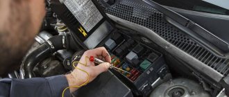
Checking engine sensors are largely similar to each other, despite the fact that these devices measure different physical quantities and values. To test most of them, an electronic multimeter is used that can measure the value of electrical resistance and voltage. However, most sensors can be tested using other methods, depending on their operating principle. Before checking, the sensors must be removed from their mounting location, because in most cases, checking directly on site is impossible.
Let's consider the purpose and methods of checking the main sensors under the hood of any modern car. Since if at least one of them fails, the operation of the entire engine will be disrupted.
Mass air flow sensor
As the name implies, abbreviated as MAF, it measures the volumetric amount of air intake by the engine. The unit of measurement in this case is kilograms per hour. For most cars, this sensor is installed on the air filter housing or on the intake manifold. Its device is simple, so it rarely fails. However, in some cases it may record and provide incorrect information.
For example, if the readings from it are overestimated by 10...20%, problems arise in the operation of the engine, in particular, the idle speed may “float”, the engine “chokes” and starts poorly. If the readings from the sensor are lower than they actually are, then the dynamic characteristics of the car decrease (it does not accelerate, it drives slowly uphill), and fuel consumption also increases.
Correct operation of the mass air flow sensor is highly dependent on the condition of the air filter. So, if the latter is very clogged, then there is a risk of debris falling on the sensor - grains of sand, dirt, moisture, and so on, and this is very harmful to it, and leads to the fact that the sensor provides incorrect information. This can also happen if the machine has a zero resistance filter (or there is simply no filter).
An interesting feature of the mass air flow sensor is that cars equipped with it cannot be tuned by increasing engine power. In particular, this applies to VAZ engines, which some car enthusiasts “pump” up to a power value of 150...160 horsepower. In this case, the sensor will obviously not work correctly, since it is simply not designed for such an amount of air volume passing into the engine.
For standard VAZ engines, the mass air flow sensor at idle speed should record the passage of about 8...10 kilograms of air per hour. When the speed increases to 3000 rpm, the corresponding value increases to 28...32 kg/hour. For engines similar in volume to VAZ ones, these values will be close or similar.
Checking the mass air flow sensor involves measuring the DC voltage it produces using an electronic multimeter.
Throttle position sensor
The sensor is designed to record the position of the throttle valve at a specific point in time. The corresponding position changes depending on whether the accelerator pedal is pressed and how far. Typically, the throttle position sensor is installed directly on the throttle and/or on the same axis as the throttle. It is noted that if an original high-quality sensor is installed on the machine, then most likely there will be no problems with its operation. However, there are many counterfeit low-quality sensors on sale (for example, made in China), which, firstly, do not last long (about a month), and secondly, provide incorrect information, which leads to the engine operating in suboptimal conditions for it.
For example, if the throttle position sensor partially fails, problems arise in the car’s response to the driver’s actions in relation to the gas pedal. For example, dips appear when it is pressed, a spontaneous increase in speed, and its “swimming”. Also, if the throttle position is faulty, jerks and dips may occur when the engine is running under load. In a word, the accelerator pedal, as it were, “begins to live its own life.”
There are known cases when TPSs failed due to the fact that they were damaged by a powerful water jet at car washes. To the point that they can simply be knocked off their seat. Therefore, you need to carefully monitor this when washing cars yourself or in a specialized establishment. In general, the throttle position sensor is a fairly reliable device. However, if it fails, it cannot be repaired, so it should only be replaced completely.
check the throttle sensor using a multimeter that can measure DC voltage in the range of up to 5 volts.
How to check sensors in a car, checking the main sensors of a car
For full interaction and control of the main parameters of car devices, special sensors are used. If a device in one system fails, it will lead to a failure in the operation of other systems. When purchasing a used car, it is important to check the car's sensors. The higher the mileage of the car, the more likely it is that devices and systems have malfunctions. Autocode will tell you how to properly check sensors on a car when purchasing.
For inspection for these purposes, you should take with you a minimum set of tools for dismantling interfering parts and an ohmmeter (multimeter).
Also read: What can you check with a multimeter?
Temperature sensor on car
One of the important devices of any car that shows the temperature of the coolant in the system. Installed directly in the cylinder head. When the sensor is faulty, a special indicator lights up on the dashboard. Here are the main signs that will indicate a malfunction of the temperature sensor:
- The engine constantly overheats.
- As the engine temperature rises, the car's drivability decreases.
- Increased fuel consumption.
- The composition of the exhaust deteriorates significantly.
How to check temperature sensors on a car? It is necessary to measure the resistance between the terminals depending on the engine temperature. The higher the temperature, the lower the resistance value should be. It will be necessary to remove the rubber casing that covers the contacts. Next, the “plus” of the measuring device is connected to the signal contact conductor, and the “minus” to ground. Then the car engine starts and warms up to certain temperatures. For each car there is a special table with resistance readings depending on temperature.
Throttle position sensor
This is an electromechanical resistor, which consists of a special stepper motor and an element with increased sensitivity. You can check the sensor on the car using a special ohmmeter; to do this, measure the resistance between the terminals. For each car model there is a standard indicator, which is prescribed in the operational documentation. The main symptoms of a malfunctioning throttle sensor:
- Sharp jumps when engine speed increases.
- Unstable engine operation at idle.
If the discrepancy between the readings does not exceed 20%, then the device is considered operational.
ABS sensor
Before purchasing a used car, special attention should be paid to the special ABS sensor. For testing, a conventional modern multimeter with full functionality is used. A more accurate check is performed at service stations using an oscilloscope.
We connect the device to the contacts, measure the resistance and compare it with the basic indicators, which are specified in the documentation for your car. During the measurement, it is necessary to shake the wires. If the multimeter readings change, this indicates an open circuit.
In addition to resistance, the ABS sensor is also checked for voltage. To do this, switch the multimeter mode from measuring resistance to measuring voltage. Next, we spin the car wheel up to 50 rpm and measure the voltage. The indicator should not exceed 2 V.
Crankshaft position sensor (CPS)
A general check of car sensors before purchase can include checking the DPKV. If the element is faulty, your car will not even start. With its help, the processes of supplying the finished combustible mixture to the cylinders and ignition are synchronized. To check the DPKV it is necessary to remove it. It is important to remember the previous position of the element; for this there are special marks on it. After removal, check for integrity. If it is damaged, it must be replaced immediately without inspection.
Next, we connect the DPKV contacts to a multimeter and measure the operating resistance. We compare this reading with the standard one, which is indicated in the operational documentation.
Before buying a used car, it will be useful to check not only the technical condition of the devices and mechanisms, but also the entire history of ownership and operation. To do this, use the Autocode service. By going to the main page of the service, you will see a line in which you need to enter the license plate number of the car.
After this, a report will appear with the characteristics and history of the vehicle. In addition, Autocode offers on-site inspection services. The help of a specialist will come in handy if you do not have the opportunity to come for an inspection yourself or do not have enough experience.
The technician will inspect the car himself and issue a professional opinion.
If you are a professional car seller, use the “Autocode Pro” unlimited car check service. “Autocode Pro” allows you to quickly check a large number of cars, add comments to reports, create your own lists of liquid vehicles, quickly compare options and store data about cars in an orderly form.
Also read: How to check your car's steering
Source: https://avtocod.ru/kak-proverit-datchiki-avtomobilya
Coolant temperature sensor
It also has other names - temperature sensor, coolant sensor. As the name implies, its task is to record the temperature of antifreeze or antifreeze and transmit this information to the engine electronic control unit (ECU). Based on the information received, the control unit adjusts the richness of the air-fuel mass entering the engine; accordingly, the colder the engine, the richer this mixture will be. The coolant temperature sensor is most often located on the exhaust pipe of the cylinder head (although there may be other options, this depends on the specific car model).
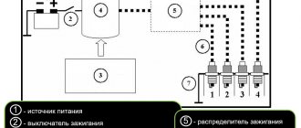
Essentially, this sensor is a thermistor - that is, a resistor that changes its internal electrical resistance depending on the temperature of its control element. The lower the temperature, the higher the resistance, and vice versa, the higher the temperature, the lower the resistance. However, the sensor supplies the ECU with a voltage value rather than a resistance value. This is implemented by the sensor control system when a 5 Volt signal is supplied to it through a resistor with a constant resistance, which is located inside the control controller. Therefore, along with the resistance, the output voltage also changes. So, if the antifreeze temperature is low, the output voltage will be high, and as it warms up, the voltage will decrease.
Signs of sensor failure:
- Spontaneous activation of the cooling fan when the engine is cold;
- the cooling fan does not turn on when the engine is hot (at extreme temperatures when it should turn on);
- problems with starting the engine “hot”;
- increased fuel consumption.
To be fair, it is worth noting that the sensor design is quite simple, and there is simply nothing to break there. However, in some cases (for example, due to mechanical damage or old age), the electrical contact inside the sensor may become damaged. The second possible cause of failure is a break in the wiring from the sensor to the ECU or damage to its insulation. As is the case with other sensors, this unit cannot be repaired and only needs to be replaced with a new one.
check the coolant temperature sensor either directly at its seat in the engine or by first removing it.
How to check the temperature sensor
First you need to figure out how to check the temperature sensor, which is mounted in the cylinder head. If there are any problems, the corresponding indicator on the dashboard will light up. But there are indirect signs that say that it is out of order:
- fuel consumption has increased sharply,
- the composition of the exhaust has changed,
- the car's controllability has decreased due to the engine temperature increasing,
- the motor often overheats.
To check, you need to find out what the resistance is between the terminals at different engine temperatures. There is an inverse relationship here - the higher the temperature, the lower the resistance. To check, you need to remove the rubber casing covering the contacts. The “plus” of the multimeter is connected to the conductor through which the signal is transmitted, and the “minus” to ground. Record the indicators that the device shows when warming up to a certain temperature. Each brand of car has its own table of standard values, which can be found in the technical documentation.
Knock sensor
The knock sensor (abbreviated DD) detects the appearance of detonation knocks directly in the engine. Typically, the knock sensor is installed directly on the engine block, most often between the second and third cylinders. Currently, there are two types of such sensors - resonant and broadband. The first of them (resonance) are considered obsolete and can only be found in engines of older designs. The resonant sensor is designed for a certain sound frequency, which corresponds to micro-explosions in the motor. A wideband sensor records sound waves in the range from 6 Hz to 15 kHz. The relevant information is transmitted to the electronic control unit, and the control unit then decides whether detonation occurs or not. And if it does exist, the ECU automatically shifts the ignition angle to avoid its recurrence.
Signs of failure of the knock sensor are the following factors:
- loss of dynamic characteristics of the car (it does not accelerate, does not pull well uphill);
- idle speed “floats”, they can also be unstable in operating mode;
- increased fuel consumption.
Checking the knock sensor can be done in two ways - by measuring the value of the output resistance, voltage, or using an oscilloscope to watch its operating mode in dynamics.
Check for VAZ 2110
Using an ohmmeter (multimeter).
For clarity, let’s look at each method of checking the crankshaft position sensor using the example of several cars.
The first will be the VAZ-2110, which uses an inductive type device.
This means that the engine in the “ten” has broken down and we can assume that this is a malfunction of the crankshaft position sensor. This is at hand - a multimeter that can work in ohmmeter mode.
This is enough to check the winding resistance.
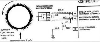
The first thing you need to do is check the device as it is installed on the car, or rather, check the gap between it and the synchronizing disk.
It is quite possible that there is no gap there due to contamination that caused the failure.
If everything is fine, take a break until we disassemble the device from the car.
On the VAZ 2110 it is located on the oil cap. pump.
Before this, it is better to check the DPKV item.
The next step is to assess the external condition. The sensor body must be intact and without signs of damage, the core must be clean, the contact wires must not be oxidized, and the wires must be undamaged.
If external contamination is visible on the ADCG, it can be washed before testing (use only pure gasoline or alcohol) and any traces of contact removed with a file.
After cleaning, rinsing and drying, you can start measuring. To do this, switch the multimeter to ohmmeter mode and connect it to the sensor contacts using a measuring tip.
During measurement, a working DPKV should have a resistance in the range of 550-570 Ohms.
For other cars, this value may be different, so it is better to find out the rated voltage of the sensor before measuring it in the technical documentation for the car.
If the resistance value is less than or greater than the specified range, the sensor is faulty and must be replaced.
This is the easiest way to check DICV, but it is also the most inaccurate. It can only give a partial idea of the state of the device, although sometimes it is quite adequate.
Oscilloscope.
The most accurate way to check this is with an oscilloscope. Therefore, let's figure out how to check the sensor on a VAZ-2110 with this device.
With this test there is no need to disassemble the ETC and all measurements are taken directly on the vehicle.
Before performing the test, you must properly connect the oscilloscope to the vehicle. Typically this device has one clamp and two probes.
The terminal must be connected to the motor ground, that is, to any metal part of the motor.
One probe is installed parallel to the sensor signal output terminal. The second probe is connected to pin 5 of the scanner connection terminal.
After connecting, switch the device to the “Induction crankshaft” mode.
Then start the engine. If it doesn't work, you'll have to crank the crankshaft with the starter so that the oscilloscope can take readings.
You can then evaluate the sensor's performance based on the resulting waveform. Any malfunctions in its operation will be reflected in the oscillogram image, and it will be clearly visible.
Oxygen concentration sensor
Another name for the sensor is lambda probe. The main task of the unit is to record the amount of oxygen in the exhaust gases. As a rule, it is installed next to the catalyst or on the exhaust pipe of the muffler. In some car models, the design provides for the use of two oxygen sensors - one before the catalyst, and the second after. The relevant information is traditionally transmitted to the electronic control unit, and it then makes a decision on the supply of fuel to the engine, adjusting the composition of the air-fuel mixture (poor/rich). If oxygen is detected in the exhaust gases, it means the mixture is lean; if not detected, it means it’s rich.
The oxygen sensor itself is quite reliable and rarely fails. However, if this happens, then the emission of harmful substances along with exhaust gases into the atmosphere increases. Externally, the failure of the lambda probe can be determined by increased fuel consumption. A conditional disadvantage of the sensor is its relatively high price compared to other car sensors.
Checking the oxygen sensor is carried out both visually and with a tester. The method of measuring voltage and sending a signal will depend on how many contacts a particular lambda has.
Oxygen device, lambda probe
The main task of this device is to record the volume of oxygen in the exhaust gases. Most often, the device is installed next to the exhaust pipe catalyst. Information from this device is sent to the ECU for processing. As a result, the composition of the air-fuel mixture is adjusted.
There is a very simple relationship here. The more oxygen the exhaust contains, the leaner the fuel. This device is quite reliable. When it fails, gasoline consumption increases.
Crankshaft position sensor
Its abbreviated name is DPKV. This is one of the main sensors of an internal combustion engine, and all its operation depends on it. The task is to generate an electrical signal about a change in the angular position of a special toothed disk mounted on the crankshaft. Based on this information, the electronic engine control unit decides at what time to supply fuel to which cylinder and light the spark plug. Typically, the crankshaft position sensor is installed on the oil pump cover. Structurally, the device is very similar to a regular magnet with a thin wire.
If the DPKV sensor fails, two situations may occur. The first is that the engine stops working completely because the synchronization of fuel supply, spark, and so on is lost. This happens most often. However, in some cases, the electronic control unit switches the engine to emergency mode, in which engine speed is limited to 3000...5000 rpm. This will activate the Check Engine light on the dashboard.
Checking the crankshaft position sensor is performed using three methods: measuring resistance, inductance, and an oscilloscope.
How to check the air sensor
An important part of the car is the mass air flow sensor. It is called MAF for short. The fuel consumption and power of the car depend on how stable it works. Before you check the air sensor, you need to remember where it is located in order to return it exactly to its original place. The sensor is installed between the air pipe that leads to the throttle valve and the corresponding filter. The sensor is needed to measure the amount of air entering the cylinders. It transmits this information to the control unit. Based on the measured indicators, “smart electronics” decides whether to increase or decrease the air supply to the mixture.
How to prove datchiki avtomobilya3
Certain signs indicate a malfunction of the device. First of all, this is a signal on the dashboard that calls for checking the engine. This also increases fuel consumption.
The most primitive, but fairly reliable way to check is to forcibly turn off the sensor and see how the running engine will work. Normally, it will operate in emergency mode, as indicated by the signal on the dashboard. You cannot drive a car for a long time with the sensor disabled, but you need to take it for a drive. The car should accelerate faster. This will show that the problem lies with the sensor. You can also use the classic testing scheme using a multimeter.
Speed sensor
It is located on the gearbox and records the shaft rotation speed, transmitting the corresponding information to the electronic control unit. And the ECU already calculates the speed based on the information received. In cars with a manual transmission, the relevant information is transmitted to the speedometer located on the dashboard. In cars equipped with an automatic transmission, based on information including from it (but not only), a decision is made to shift gears up or down. Also, based on information from the speed sensor, the car’s mileage is calculated, that is, the operation of the odometer.
The sensor supplies the electronic control unit with voltage pulses in the range from 1 to 5 Volts with a frequency proportional to the wheel speed. Based on their frequency, the device calculates the speed of the machine, and based on the number of pulses, the distance traveled.
The sensor itself is a fairly reliable device, but in some cases the plastic gear wears out and its contacts may oxidize, which leads to ECU problems. In particular, the control unit cannot understand whether the car is standing or driving, and at what speed. Accordingly, this leads to problems in the operation of the speedometer, as well as gear shifting in an automatic transmission. Also, when the sensor fails (oxidation of the contacts), reduced idle speed values are noted; during sharp braking, the engine speed “sags” greatly, and the dynamic characteristics of the car decrease (it accelerates poorly, does not pull). On some cars (for example, on some Chevrolet models), the electronic control unit turns off the engine in emergency mode, and movement becomes impossible.
Checking the speed sensor requires using one of three available methods.
Camshaft position sensor
Similar to the DPKV, the camshaft position sensor (abbreviated DPRV) reads information about the angle of its position and transmits the corresponding information to the ECU. Based on the information received, the control unit makes a decision to open the fuel injectors at a certain point in time. Old injection engines (up to about 2005) did not have a camshaft position sensor installed. Because of this, fuel injection into the intake manifold on such engines was carried out in pairs-parallel mode, in which two injectors open simultaneously, which is characterized by excessive fuel consumption.
On engines on which DPRV is installed, so-called phased fuel injection is performed. That is, only one injector nozzle opens, where fuel should be supplied at the moment. As for the location of the sensor, on eight-valve engines it is mounted at the end of the cylinder head. On sixteen-valve power units, this sensor is also usually located on the cylinder head, near the first cylinder.
If the camshaft position sensor fails, the electronic control unit switches the engine to emergency mode, in which the injectors operate in pairs-parallel mode, opening simultaneously. This leads to excessive fuel consumption by 10...15%, in some cases the engine “troubles”. Typically, this generates an error signal in the ECU and activates the Check Engine light on the dashboard. Therefore, it is necessary to perform additional diagnostics using an electronic error scanner.
The DPRV sensor can be checked using a multimeter and/or an oscilloscope.
What is DPKV
As mentioned above, DPKV stands for crankshaft position sensor. It determines the position of the crankshaft at each moment in time, thereby monitoring its rotation frequency, and ensures the correct functioning of the ignition system.
DPKV transmits the following indicators to the control unit:
- the moment the pistons reach TDC and BDC in the first and last cylinders;
- crankshaft position and speed.
Based on this data, the vehicle's ECU can regulate the following processes:
- ignition timing for each cylinder;
- control of fuel injection through injectors, the required amount of fuel;
- camshaft rotation angle (variation of valve timing);
- operation of the fuel vapor recovery system (control of the canister purge valve).
Not a single injection engine with an electronic control unit can operate without DPKV. There is no need for it in carburetor engines, since a saturated air-fuel mixture enters the engine in equal quantities, regardless of needs. The injector allows you to regulate the fuel supply and save fuel consumption. And it is on the basis of data from the DPKV that the system regulates its work.
Many drivers confuse the DPKV with the camshaft position sensor (CPS). Although their structure and purpose are largely similar, there are differences. DPRV determines the angular position of the camshaft and is responsible for fuel injection into the cylinders and ignition at the right time. The DPRV uses a permanent magnet and its operation is based on the Hall effect. We can say that DPKV and DPRV work in tandem with each other, but the first is more important for engine operation.
This is interesting: Where is the main Audi plant located?
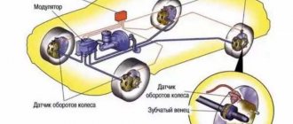
Anti-lock braking system sensor
As the name implies, this unit is key to the operation of the anti-lock braking system (abbreviated as ABS). On vehicles equipped with this system, there is one such sensor on each wheel. Their task is to record the speed of rotation of the wheel at a specific moment in time. The location method for cars may be different, but in any case the sensor will be located in close proximity to the wheel rim, in the area of the hub. Usually signal wires go to it, along which you can determine the exact location of the sensors on the front and rear wheels.
As a rule, the sensors themselves are quite reliable and rarely fail, except due to mechanical damage associated with the fact that they are installed in close proximity to the wheel and road. More often, the wiring going to/from them is damaged. It may fray or the insulation on the wires will be damaged. If the electronic control unit “sees” that incorrect information is coming from the sensor/sensors, then it activates the Check Engine warning light on the dashboard, and simply turns off the ABS system in emergency mode. Naturally, this leads to a decrease in driving safety.
Checking the ABS sensor is carried out in various ways - by measuring resistance, voltage or using an oscilloscope (the most advanced method). On newer cars, Hall effect sensors are installed as ABS sensors.
Device and use
The simplest way to measure R is through indirect calculations. According to Ohm's law, it is enough to know the voltage and current in a section of the circuit to determine the value of Ω with sufficient accuracy. Despite the fact that this method provides good results, in itself it is not very practical for household needs. It is convenient to measure resistance with devices more suitable for this purpose - ohmmeters, which are essentially a voltage source, voltmeter and ammeter combined in one housing. The most widespread are universal devices that include this function.
Analog multimeters
This instrument's scale responds to the current flowing through the component during testing. High resistance corresponds to low current, which is reflected by the position of the arrow on the left side of the dial, high, respectively, on the right. One of the features of the device is that it needs to be calibrated before operation. This is done by shorting the probes and setting the scale to zero at this moment.
Each time, before measuring resistance with a multimeter in a different range, it is necessary to check the deviation from the zero value, since the position of the arrow may change in different modes. In addition, after each break, the tester must be calibrated again, since the measurement itself depends on the state of the battery. The process of working with an analog multimeter consists of the following steps:
- Selecting the element whose resistance you want to know.
- Attaching probes to the device. As a rule, the case has several sockets for connection and one of the plugs should be in the common connector, and the second in the socket marked Ω.
- Selecting the required range. It should be such that the most accurate value is determined on the scale. Usually the function switch is pre-set to maximum resistance mode, and after the first test the range is refined.
- Calibration (zeroing) of the device.
- Taking measurements and adjusting the range.
- Turn off the multimeter. It is advisable to set the switch to measure maximum resistance. This way you can insure against damage to the tester the next time you turn it on due to accidental use without the correct settings.
Analog multimeters have found widespread use as part of test equipment. They are relatively cheap and offer a reasonable level of accuracy and performance.
Digital multifunction devices
Measuring resistance with a digital multimeter is much easier and faster than with an analog one. First of all, because when using it there is no need to reset the counter. A few simple steps required to test a resistor with a multimeter:
- Select a component to test.
- Connect the probes to the correct sockets. Most devices have red and black wires and corresponding markings at the connection points on the body. There are usually several sockets for connecting red. Necessary items are marked with an Ω icon.
- Select the appropriate range. The overall spectrum can vary from 1 ohm to 1 megaohm. Some modern devices are equipped with an automatic selection function. When using simpler instruments, you should start working in high resistance ranges and, if necessary, reduce the measurement limits to obtain a more accurate result.
- Turn off the device.
It is important to remember that measuring the resistance of components is only permissible with the power turned off in the circuits being tested. Any readings from the device are meaningless if there is a potential difference in the tested area.
Scope of application of multimeters
The device is indispensable for specialists and amateurs dealing with electronics. It can be used to understand what is happening in circuits, find faults and troubleshoot problems. As an ohmmeter, it is used by radio amateurs to measure the resistance of variables (potentiometers) and fixed resistors. Areas in which multimeters are widely used:
- Radio component testing lines. Resistors, inductors and chokes require monitoring by the manufacturer for compliance with specified resistance tolerances, so quality control workers are equipped with multimeters.
- Factories producing switches, connectors, relays and fuses. They need to check the contact resistance for compliance with the established limit.
- Enterprises that install power cables and distribution devices. Their work requires constant monitoring of the quality of connections to achieve the lowest possible resistance. If this is not done, poor contacts in connections or switches will sooner or later fail due to overheating.
- Organizations related to the maintenance of electrical facilities. The basis of control in such activities is the continuity of cable insulation. The wiring resistance is measured with a megohmmeter, but usually, in order to detect defects, it is enough to ring the elements suspected of malfunction with a multimeter.
- Service centers for repairing household appliances. All modern electrical equipment is controlled electronically. Measuring the resistance of circuit components is one of the main diagnostic methods.
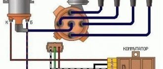
Hall Sensor
Sensors whose operation is based on the Hall effect (which is why they are called that) are used in electronic ignition systems. Their use provides two main advantages - the absence of a contact group (a problematic unit that can sometimes burn out), as well as providing a higher voltage on the spark plug (30 kV instead of 15 kV). However, similar sensors are also used in other systems of modern cars - brake, anti-lock braking, and tachometer operation. However, the principle of testing is almost the same and consists of measuring the resistance and/or voltage on the sensor with an electronic multimeter.
If the Hall sensor located in the electronic ignition system fails, the following external signs of this failure occur:
- problems with starting the engine, up to complete inability to start it;
- problems with the engine idling (interruptions appear, unstable engine speed);
- twitching of the car when driving in a mode where the engine has reached high speeds;
- The engine stalls while the car is moving.
A Hall sensor is a fairly simple and reliable device, but in some cases it can “lie,” that is, produce incorrect data. If, as a result of the test performed, it turns out that the sensor is completely or partially out of order, then it is unlikely to be repaired (and there is no point in doing so), so it is necessary to replace it. The sensor in the ignition system of a carburetor car is located in the distributor.
Checking the Hall sensor in the ignition system can be done in one of four ways.
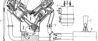
Oil pressure sensor
There are two types of oil pressure sensors (or oil pressure sensors for short) - mechanical (considered obsolete and installed, accordingly, on old cars) and electronic (modern, installed on most modern cars). Regardless of its type, the position of the oil pressure sensor is usually located in the area of the oil filter in the engine compartment.
Oil pressure sensors are fairly reliable devices (although the mechanical one fails more often, since its design has moving electrical contacts that fail over time), but malfunctions in their wiring occur (broken wires, damaged insulation). Signs of sensor failure will be problems with indicating pressure and/or oil level in the engine.
Please note that if problems arise in the operation of the oil pressure sensor, diagnostics must be performed as quickly as possible, since the low level of lubricating fluid in the engine crankcase is a critical indicator, and it must be kept at a normal value at all times!
Checking the oil pressure sensor is only possible when removing it from its seat. To check, the car enthusiast will need an electronic multimeter (it can be replaced by a control lamp) and an air compressor.
Fuel pressure sensor
The fuel pressure sensor is designed directly so that the ECU actually receives information about the value of this pressure. These devices are installed on both gasoline engines equipped with injectors and modern diesel engines with a Common Rail fuel system. These sensors are installed in the engine fuel rail. In both gasoline and diesel engines, the task of the fuel pressure sensor is the same, and is to ensure the pressure value within certain limits necessary for the normal functioning of the engine, ensuring its rated power, and normalizing noise during its operation. Some systems provide for the installation of two sensors - in high and low pressure systems.
Structurally, the sensor is a sensor element consisting of a metal membrane and strain gauges. The thicker the membrane, the greater the pressure the sensor is designed for. The task of strain gauges is to convert the mechanical bending of the membrane into an electrical signal. The output voltage value is about 0...80 mV.
If the pressure value goes beyond the specified limits (these values are stored in the memory of the electronic control unit), then the control valve in the fuel rail is activated in the system, and the pressure is adjusted accordingly. If the sensor fails, the ECU activates the Check Engine light on the dashboard and begins using standard (non-adjustable) fuel consumption values. This leads to the engine operating in a non-optimal mode, which is reflected in excessive fuel consumption and loss of engine power (dynamic characteristics of the machine).
You can read information about checking the fuel pressure regulator
MAP sensor
In the classic version, the absolute air pressure (ABP) sensor is made of four resistors that have a variable resistance value and are connected by an electronic bridge. They are glued to a diaphragm, which either compresses or expands depending on what incoming air pressure is currently available in the intake manifold. The task of the DBP is to record changes in pressure in the intake manifold depending on changes in load and crankshaft speed, converting this information into an output electrical signal. This signal is traditionally sent to the electronic control unit, and based on this information, the ECU changes the duration of fuel supply to the combustion chambers, as well as the ignition timing.
As a rule, the air pressure sensor is located on the intake air tract (depending on the design of the particular vehicle). When it fails, problems begin in engine operation - idle speed “floats”, the car loses dynamic characteristics, and fuel consumption increases. If the sensor is damaged, it must be replaced with a new one.
How to check DBP
If the absolute air pressure sensor in the intake manifold malfunctions, the car’s engine will not operate stably and its power will decrease. You can check the functionality of the DBP sensor with a multimeter and a syringe. But first you need to clean it Read more
Information sensors
Oxygen sensors (02)
The oxygen sensor produces a voltage signal that changes with the difference between the oxygen content of the exhaust gases and the ambient air.
Crankshaft position sensor (CPS)
The crankshaft position sensor provides the ECM with information about the crankshaft angle and rotation speed.
Camshaft position sensor (CMP) (models produced since 1998)
The camshaft position sensor provides a signal that the ECM uses to identify the No. 1 cylinder and synchronize the sequential fuel injection system.
Fuel composition sensor ( AFS ) (models produced since 2001)
Some models are equipped with a mixture sensor, which is installed in front of the catalytic converter. Its purpose is the same as that of oxygen sensors.
Coolant temperature (ECT) sensor
The coolant temperature sensor monitors engine coolant temperature and sends a voltage signal to the ECM, which uses this information to regulate fuel mixture, ignition timing, and control the exhaust gas recirculation (EGR) system.
Intake air temperature ( IAT ) sensor (pre-2000 models)
The IAT sensor provides the ECM with information
O. intake air temperature. The ECM uses this information to regulate fuel delivery, ignition timing, and EGR system operation. On these models, this sensor is integrated into the mass air flow (MAF) sensor.
Throttle Position Sensor ( TPS )
The TPS sensor senses throttle valve movement and records its position, then sends a voltage signal to the ECM. The sensor signal voltage changes in accordance with the change in the throttle position angle - opening or closing the throttle.
Intake absolute air pressure (IAP) sensor
The MAP sensor measures the amount (volume) of air entering the engine intake manifold. The MAP sensor (as well as the IAT sensor) supplies the ECM with information about the volume of incoming air and its temperature, which helps the ECM determine the most accurate fuel/air ratio in the working mixture.
MAF sensor (models produced since 2001)
The sensor measures the mass of air passing into the intake tract by determining the volume and weight of portions of air passing through a heated conductive filament located in the inlet air stream.
Vehicle Speed Sensor ( VSS )
The sensor reports vehicle speed information to the ECM.
Fuel vapor pressure sensor (VPS)
The sensor is part of the EVAP system and is used to monitor the vapor pressures in the EVAP system. The ECM uses this information to turn the charcoal evaporation canister .
Power Steering Fluid Pressure Contact Sensor ( PSP )
The sensor is used to increase the idle speed when maneuvering the vehicle at low speed.
Transmission sensors
The ECM receives information from the following sensors located inside or connected to the transmission: the direct clutch speed sensor and the vehicle speed sensor.
Phase sensor
The operation of the phase sensor is based on the Hall effect mentioned above. Its task is to fix the so-called top dead center of compression of the piston of the first cylinder. The relevant information is transmitted to the ECU, and based on it, phased fuel injection is carried out into the remaining cylinders in accordance with the operating order of the engine cylinders. As a rule, the installation location for the phase sensor is the rear of the cylinder head.
If the phase sensor fails, a misphasing of fuel injection into the cylinders occurs, that is, the engine switches to unphased fuel injection mode. The electronic control unit then activates the Check Engine warning light on the dashboard. At the same time, the engine begins to work unstably, up to a complete stop, the dynamics of the car decrease in different driving modes, the engine “troubles”. In some cases, on the contrary, increased fuel consumption is observed. Replacing the sensor is not difficult. Usually all you need to do is use a wrench.
You can see partial information on how the phase sensor is checked
Camshaft position sensor (CPR)
The camshaft position sensor is used to detect the angular position of the camshaft. The Engine Control Module (ECU) uses this signal to determine the firing sequence of the engine's cylinders.
What function does the sensor perform: determining the position of the engine camshaft, determining the top dead center during the compression stroke in the cylinder block. Thanks to the sensor, the sequential injection of fuel and ignition is controlled.
Symptoms: When the camshaft position sensor fails, engine power output decreases. An ignition failure will also occur: as a rule, when you press the gas pedal, the car will shake but accelerate slowly. This is due to loss of power. Also, if the sensor fails, a “Check engine” indicator may appear on the dashboard. Attention! When the engine warms up, the indication may disappear or appear again.
see also
Mass air flow sensor: Symptoms of malfunction and replacement cost
Intake air temperature sensor
The sensor is abbreviated as DTVV or in the English abbreviation IAT. It is necessary to ensure that the air-fuel mixture has the optimal composition for engine operation. As a rule, the intake air temperature sensor is installed on the air filter housing or behind it, that is, in places where air is directly drawn into the engine. In some cases it may be part of the mass air flow sensor. Failure of this element threatens unstable engine operation, “floating” idle speed (they will be either too high or too low), loss of vehicle dynamics and power. Also, if the unit is faulty, there will be problems with starting the engine, as well as significant excessive fuel consumption, especially in severe frosts.
A sensor malfunction can be caused by damage to its electrical contacts, failure of its signal wiring, low voltage in the automotive electrical network, a short circuit inside the sensor, or dirty contacts. To be fair, it should be noted that this sensor, unlike many others, can be restored to its functionality, that is, without replacement. Sometimes basic cleaning helps (you need to do it carefully).
The operation of the intake air temperature sensor is checked using an electronic multimeter.
Motion sensor design and technology
- Let's start with interrupters. As we already know, the device consists of an emitter and a receiver. The simplest implementation is a photo of a couple with a lens that forms a directed beam. However, such devices have not been used for several decades. Which sensor can be considered modern? One that uses a coherent or polarized beam. That is, a laser.
For reference: The laser beam can be visible or invisible. This expands the capabilities of the device when used in security systems.
There are two design options: in one housing or with a separate receiver and transmitter. In the first case, it is necessary to electrically combine two nodes into a single electrical system. The second option uses a reflective surface and the beam is returned to the receiving sensor located next to the emitter.
This design is not suitable for the street; there are too many potential objects to trigger (birds, animals). Therefore, it is necessary to duplicate rays located at a distance (to avoid false alarms on small objects).
- Reflectors are also emitters, with their own receiver in the housing. According to the use of waves, they are divided into three groups:
- How does a microwave motion sensor work? It emits microwave waves, which form a certain background of high-frequency waves around it. They are reflected from objects, and the “brain” of the sensor remembers a three-dimensional image in the form of radiation levels in different planes. When a foreign object appears inside this background, the level of reflected radiation changes. This is detected by the receiver and an alarm is activated. After the object disappears, the sensor returns to its resting state.
- Ultrasound. We know its practical application from the ultrasound device, which is used in medicine. There are other uses: motion sensors. The ultrasound generator constantly emits ultrasound waves in a given sector. It is difficult to check (detect) the operation of the device, which is why these types of sensors are popular in security systems. When an obstacle occurs, sound waves are returned and recorded by the receiver. The sensor is triggered.
Another similar option is an electromagnetic sensor. Registers changes in the magnetic field when volumetric objects enter the sector. Lower sensitivity, high dependence on interference.
Checking the sensors
In most cases, the verification process is simple and does not take much time. Before performing the test, it is recommended to scan the memory of the electronic control unit for errors using a special scanner (for example, the popular ELM 327 device or its equivalent). This will make it easier to check both a specific sensor and a malfunction of the vehicle as a whole.
Sometimes situations arise when the location of a particular sensor is unknown. In this case, it is better to seek help from the manual. Also on specialized websites there is information about the position of sensors on specific car models.
Conclusion
Before checking a particular sensor, you need to make sure that the signs of failure indicate the failure of a particular sensor. If you have doubts about this, it is better to seek help from a car service center. Direct testing in most cases is performed using an electronic multimeter capable of measuring electrical resistance and DC voltage in the range of up to 12 Volts. Therefore, purchase such a device if you don’t already have one. It is not necessary to take expensive samples; a device from the middle price category is quite sufficient (you should not buy a very cheap one either, since it may show incorrect data). Well, to dismantle the sensors, you need to have regular plumbing tools on hand - wrenches, screwdrivers, and so on.
Checking the inside of the sensor
To check the electronic circuit of the device, it must be disconnected from the network, dismantled and the housing removed. To check the board, it is enough to conduct a visual inspection - serious defects, as a rule, become noticeable to the naked eye. The circuit should not have swollen, darkened, loose, fallen off or cracked parts. The presence of at least one component that is faulty or has fallen out of the general circuit leads to a distortion of performance characteristics. You should also check the integrity of the soldering points of the elements and conductive paths.
If external inspection convinces of its serviceability, the motion sensor for turning on the light must be checked. To do this, you can use a standard incandescent lamp.
Attention! This instruction describes work with high voltage, which is hazardous to health. Be extremely careful when carrying out work and do not take risks if you believe that personal experience in electrical installation is not sufficient to guarantee safety.
It is better to supply electric current to the sensor through a 1-2 A circuit breaker; to protect against electric shock, it is better to generally supply power through a circuit breaker. After applying current, using a voltmeter or multitester, its functional elements are checked for the presence of voltage. An important element of the circuit is the control transistor of the operation relay. You also need to check the output relay. Due to the constant switching of external load, its contact group can quickly exhaust its working resource.