Different cars, as a rule, are equipped with gasoline or diesel engines of different power, with different amounts of torque and, accordingly, different crankshaft speeds.
Also, regardless of the type of internal combustion engine, cars are equipped with different gearboxes. At the same time, for most gearboxes, such a concept as the main gear of a car is relevant. Next we will talk about what a final drive is and what it is needed for.
Design and principle of operation
The principle of operation of the final drive is quite simple to understand. When the car is moving, torque is transmitted from the motor to the variable task box. After which, due to the main gear and differential, it is transmitted to the drive shafts. Accordingly, the main gear acts as a changing element. It changes the torque transmitted to the wheels and changes the speed of rotation of the wheels. The main characteristics of this gearbox include the gear ratio. The parameter reflects the ratio of the number of teeth of the driven gear to the driving gear. The larger the gear ratio, the faster the car will accelerate. However, in this case, the value of the maximum speed will inevitably decrease. The maximum speed is increased by reducing the gear ratio.
The main gear design is also quite simple. It consists of two gears of different sizes. It is subject to special requirements, including minimum noise and vibration levels during operation, minimum fuel consumption and high efficiency. The main gear must provide high traction and dynamic characteristics, be technologically advanced, reliable and undemanding in terms of maintenance.
This is interesting: Which engine runs on gas 66
Primary requirements
The GP consists of 2 gears. The drive shaft is smaller and is connected to the secondary shaft of the gearbox. The driven gear is larger in size than the drive gear and interacts with the differential and wheels of the car. Main requirements for transfer:
- lowest level of noise and vibration during operation;
- lowest gasoline consumption;
- increased efficiency;
- ensuring increased traction and speed parameters;
- manufacturability;
- smallest dimensions (to increase ground clearance and reduce the level of the bottom of the car);
- less weight;
- increased strength;
- minimal maintenance.
The transmission efficiency can be increased by increasing the quality of the teeth of the two gears and increasing the strength of the parts, as well as by using rolling bearings in the design.
Reducing vibration and noise during operation as much as possible is necessary for vehicle gearboxes. To do this, it is necessary to ensure good lubrication of the teeth. This will increase the accuracy of fastening the gears and increase the diameter of the shafts. It is also worth taking other measures to increase the reliability of the mechanism parts.
Differential
The differential is a planetary mechanism designed to distribute torque between the drive axle shafts of a tractor or car and ensure rotation of the drive wheels at different frequencies when moving along a curve or uneven path. When turning or on an uneven path, the drive wheels move in arcs of different lengths. If both wheels were located on a common shaft, then their movement would be accompanied by slipping, tire wear and breakdowns. Therefore, the drive wheels are installed on separate shafts - axle shafts, connected by a differential.
Let us consider the operating principle of the differential according to the diagram shown in Figure a. Gears - satellite 7 (Figure a) is in mesh with racks 6 and 8 (in the actual design these are gears 6 and 8). A force P is applied to the axis 10 of gear 7, tending to move this gear upward.
If the resistance of racks 6 and 8 to movement by force P is the same, then equal forces P/2 act on their teeth and the racks move upward as a single unit with gear 7. However, when the resistance to movement of one of the racks, for example rack 6, will be greater than racks 8 , gear 7 begins to rotate around its axis and, rolling along rack 6, moves rack 8 up faster. In this case, the speed of movement of rack 8 increases as much as the speed of movement of rack 6 decreases. If the resistance to movement of rack 6 is increased so that it stops, then gear 7, rolling along it, will drag rack 8 up with it, and the speed of movement of rack 8 will be 2 times the speed of axis 10.
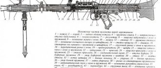
Drawing. Diagram of the differential and its locking mechanism: a - diagram of the differential operation; b - differential diagram with a locking mechanism; 1 - body; 2 — cam on the differential housing; 3 — differential lock mechanism fork; 4 - movable cam clutch; 5, 9 — axle shafts; 6, 8 — axle gears; 7 — satellite; 10 — satellite axis; 11 — driven bevel gear of the main gear.
Now let's look at a real differential circuit (Figure b). In the bosses of the housing 1, a satellite gear 7 is freely installed on the axis 10. The holes in the side bosses of the housing serve as supports for the axle shafts 5 and 9 with bevel semi-axial gears 6 and 8 mounted on them, meshed with the satellite gear 7. Rotation to the differential housing 1 is transmitted from the driven gear 11 main gear. If axle shafts 9 and 5 have the same resistance to rotation, then satellite 7, jammed by gears 6 and 8, is stationary on axis 10 and the entire system rotates as a single unit.
If the resistance to rotation of one axle shaft, for example, axle shaft 9, is greater than the resistance of axle shaft 5, then the satellite 7, turning on its axis, will slow down the rotation of gear 8 and speed up the rotation of gear 6, just as it was in the example with the movement of gear 7 and racks 6 and 8 (see figure a).
Changing the rotation speed of the axle shafts by the differential when the resistance on the wheels fluctuates reduces the tractor's maneuverability on moist or loose soil. In difficult soil conditions, it is better to turn off the differential to increase the traction of the wheels. For this purpose, tractors are equipped with differential locking mechanisms, very diverse in design.
Differential locking mechanisms
Differential locking mechanisms are divided into:
- forced
- automatic
- self-locking
And by drive type:
- mechanical
- hydraulic
Forced (mechanical) differential locking occurs when the movable cam clutch 4 (see Figure b), installed on the splines of the tractor axle shaft 5, engages with the cams 2 on the differential housing 1. In this case, the rotation speeds of the differential housing 7 and the axle shaft 5 will be the same, i.e. the differential will be locked.
The locking mechanism is activated by a pedal (or handle), and it is turned off by a pull-out spring when the force applied by the driver stops.
Automatic differential lock allows the driver not to expend any effort - the process of turning the mechanism on and off occurs automatically. Automatic differential locking is used on tractors MTZ-80, MTZ-82, T-150K, etc.
Variety of final drives
As we already understood, the final drive of a car is a very serious unit. It is clear that for such a responsible task that is entrusted to him, a reliable and at the same time simple engineering solution is necessary, and here wide open spaces for action have opened up for designers. Let's look at the types of final drives of cars. Depending on the number of gears, this unit can be like this:
- single;
- double.
The first type is a combination of two gear parts - the drive and driven gears. It is most common among cars and small trucks. Double final drives have, as you might guess, several pairs of gears, and are usually used where an increase in the gear ratio is necessary, for example, in buses and special equipment.
The picture would be incomplete without mentioning the types of gear connections used. There are many of them, and the following are distinguished:
- cylindrical;
- hypoid;
- conical;
- worm-type
The cylindrical final drive of a car is the most popular type for a configuration with front-wheel drive, as well as a transversely mounted engine and gearbox. It uses, as the name suggests, cylindrical helical, spur or chevron gears. The gear ratio of such units ranges from 3.5 to 4.2 - this is no longer possible, since the dimensions and noise from operation increase enormously.
No less popular, but true for classic rear-wheel drive vehicles, are the so-called hypoid gears. Their key feature is curved teeth, which makes it possible to transmit high torque values.
In addition, the gears in this case can be offset relative to each other, which allows, for example, to lower the floor level in the car. The main gear of a car of this type has a gear ratio in the range of 3.5-4.5.
As for bevel and worm mechanisms, they are less common. You can see the final drive of a car of these types on various vehicles with rear drive wheels, but due to their design features, they are currently used less and less. The disadvantages of the former include large size and noise, while the latter require high precision in manufacturing, which entails extra costs.
Well, dear readers of our blog, we got acquainted with the purpose of the final drive of a car, found out what this unit could be and where it is located. In the next publication we will look at another, no less important unit of the machine. Which? Subscribe to us and be among the first to know about it!
Purpose of main gear
The main purpose of the main gear in the transmission is to transfer engine traction to, so to speak, the “end user” - the wheels. If the car is rear-wheel drive, then the thrust from the gearbox through the driveshaft is transmitted to the main gear, and that, in turn, redirects the power flow to the wheels through axle shafts (if the rear suspension is dependent and has an axle) or drive shafts with constant velocity joints (velocity this will be discussed further). If the car is front-wheel drive, then the main gear is connected directly to the gearbox through a gear.
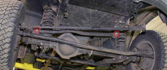
There is such a thing as a continuous bridge. It means that the main gear together with the differential are located in a housing to which two axle shaft housings are initially connected or cast together with it. Axle shafts are the shafts that connect the differential and final drive to the wheels. This design is part of the dependent suspension of the car, as it rigidly connects the right and left drive wheels. The axle shaft rigidly connects the wheel and the main gear, that is, when overcoming any obstacle, the entire bridge moves along with the wheels and all contents. We remove the axle housing, install the main gear housing on the body or subframe, connect the wheels with the main gear using drive shafts through constant velocity joints and get a split axle and independent wheel suspension. All this is described in more detail below in the section “Main drive device” and is presented in Figure 5.32.
Note The final drive serves to reduce the speed transmitted from the engine to the wheels and increase traction. It ensures the transmission of rotation from the driveshaft to the axle shaft at an angle of 90° in a classic car layout (which is described in detail in Chapter 3). In the main transmission, gear transmissions, single or double, are used.
Final drive device
The main gear consists of two gears, or more precisely, a bevel gear (in Figure 5.33 - drive gear) and a bevel gear (in Figure 5.33 - driven wheel).
Figure 5.33
The gear is the driving element (thrust from the gearbox and engine is supplied to it), and the wheel is the driven element (receives thrust from the gear and redirects it at an angle of 90 degrees).
Gears are manufactured with helical teeth, which increases the strength of the teeth, increases the number of teeth in mesh at one time, and makes the gears operate smoother and quieter.
In addition to a simple bevel gear transmission, in which the axes intersect each other, a hypoid transmission is used in passenger cars (shown in Figure 5.34). In this gear, the teeth have a special profile and the axis of the small bevel gear is shifted downward relative to the center of the large gear by a certain distance “S”. This makes it possible to position the propeller shaft lower and reduce the height of the convex upper part of the tunnel to accommodate the shaft in the body floor, resulting in more comfortable placement of passengers in the body. In addition, it is possible to slightly lower the vehicle's center of gravity and increase its stability when driving. Hypoid gearing has smoother operation, higher tooth strength and wear resistance.
Note However, the hypoid transmission has one unpleasant feature: the jamming threshold during reverse motion. Calculations for this transmission, of course, exclude this possibility, but it is always worth remembering that this main gear can jam if the calculated speed is exceeded (when rotating in the opposite direction). So be careful when choosing your reverse speed.
For hypoid transmissions, it is necessary to use special grades of lubricant due to the high pressure between the teeth during operation and the high speeds of relative sliding between the teeth. In addition, higher accuracy of transmission installation is required.
Figure 5.34 Elements of the final drive. Hypoid transmission.
Principle of operation
General view of a hypoid final drive
The principle of operation of the final drive is quite simple: while the car is moving, torque from the engine is transmitted to the variable gearbox (Gearbox), and then, through the main gear and differential, to the drive shafts of the car. Thus, the final drive directly changes the torque that is transmitted to the wheels of the machine. Accordingly, through it the speed of rotation of the wheels also changes.
The main characteristic of this gearbox is the gear ratio. This parameter reflects the ratio of the number of teeth of the driven gear (connected to the wheels) to the drive gear (connected to the secondary shaft of the gearbox). The higher the gear ratio, the faster the car accelerates (more torque), but the maximum speed decreases. Reducing the gear ratio increases the maximum speed, while the car begins to accelerate more slowly. For each car model, the gear ratio is selected taking into account the characteristics of the engine, gearbox, wheel size, brake system, etc.
Final drive device
In fact, the main gear is nothing more than a gear reduction gearbox, in which the drive gear is connected to the secondary shaft of the gearbox, and the driven gear is connected to the wheels of the car. According to the type of gear connection, the main gears are divided into the following types:
- cylindrical - in most cases used on cars with a transverse engine and gearbox and front-wheel drive;
- conical - used very rarely, as it has large dimensions and a high noise level;
- Hypoid is the most popular type of final drive, which is used on most cars with classic rear-wheel drive. Hypoid transmission is characterized by its small size and low noise level;
- worm - practically not used on cars due to the complexity of manufacturing and high cost.
It is also worth noting that front-wheel drive and rear-wheel drive vehicles have different final drive locations. In front-wheel drive vehicles with a transverse gearbox and power unit, the cylindrical main gear is located directly in the gearbox housing.
In cars with classic rear-wheel drive, the main gear is installed in the drive axle housing and connected to the gearbox via a cardan shaft. The functionality of the hypoid transmission of a rear-wheel drive car also includes a 90-degree rotation due to bevel gears. Despite the different types and locations, the purpose of the final drive remains the same.
Advantages and disadvantages
- Cylindrical main gear. The maximum gear ratio is limited to 4.2. A further increase in the tooth ratio leads to a significant increase in the size of the mechanism, as well as an increase in the noise level.
- Hypoid main gear. This type is characterized by low tooth load and reduced noise level. In this case, due to the displacement in the meshing of the gears, sliding friction increases and efficiency decreases, but at the same time it becomes possible to lower the driveshaft as low as possible. Gear ratio for passenger cars – 3.5-4.5; for freight – 5-7;.
- Bevel main gear. Rarely used due to its large size and noise.
- Worm main gear. This type of gear connection is practically not used due to the complexity of manufacturing and the high cost of production.
Types and their applicability
The main characteristic of the main gears is the type of gears and the type of tooth engagement between them. The following types of gearboxes are used on cars:
- Cylindrical
- Conical
- Hypoid
- Worm
Types of main gears
Spur gears are used in the main gears of front-wheel drive cars. The absence of the need to change the direction of rotation allows the use of such a gearbox. The teeth on the gears are oblique or chevron.
The gear ratio for such gearboxes is in the range of 3.5-4.2. A larger gear ratio is not used, since this requires increasing the size of the gears, which is accompanied by an increase in the noise level of the transmission.
Bevel, hypoid and worm gears are used where it is necessary not only to change the gear ratio, but also to change the direction of rotation.
Bevel gearboxes are usually used on trucks. Their peculiarity comes down to the fact that the gear axes intersect, that is, they are on the same level. In such gears, oblique or curved teeth are used. This type of gearbox is not used in passenger cars due to its significant overall dimensions and increased noise.
On rear-wheel drive cars, a different type is most often used - hypoid. Its peculiarity is that the gear axes are shifted. Due to the location of the drive gear lower relative to the driven axis, it is possible to reduce the dimensions of the gearbox. Moreover, this type of transmission is characterized by increased resistance to loads, as well as smooth and silent operation.
Worm gears are the least common and are practically not used on cars. The main reason for this is the complexity and high cost of manufacturing the components.
Who's in charge here and why?
So, the main transmission of a car is a unit, without which the efforts of the engine and gearbox would be a waste of energy. Why? The fact is that it is she who is responsible for transmitting torque from the gearbox directly to the drive wheels.
In addition, rotation, as a rule, still needs to change direction - from longitudinal (along the axis of the car) to transverse in order to get to the wheels. And all this is performed, in fact, by one gear mechanism, also known as a gear reducer. In addition to everything, the gear ratios are selected in such a way as to increase the torque of the motor.
This is interesting: What is an adsorber in a car?
Why is the final drive needed and what is it?
As you know, today the following types of gearboxes are installed on cars:
- (gear selection is done manually);
- (provides automatic selection of gear appropriate to current driving conditions);
- (provides a smooth change in the gear ratio.);
- (manual transmission, clutch release and gear shift functions are automated).
The main task of the gearbox is to transmit and change torque from the engine to the drive wheels with the ability to change gear ratios. At the exit from the box, the torque is small, and the rotation speed of the output shaft is high.
To increase torque and reduce rotation speed, the vehicle's main gear, which has a certain gear ratio, is used. The final drive ratio depends on the type, purpose of the vehicle and engine speed. Typically, the main gear ratios for passenger cars are in the range of 3.5-5.5, and for trucks 6.5-9.
Purpose, design features
The main task of this element is to change the torque before applying it to the wheel drive. The gearbox does the same, but it has the ability to change gear ratios by engaging certain gears. Despite the presence of a gearbox in the design of the car, the torque output from it is small, and the rotation speed of the output shaft is high. If you transfer rotation directly to the drive wheels, the resulting load will “crush” the engine. In general, the car simply will not budge.
The final drive of the car provides increased torque and reduced rotation speed. But unlike a gearbox, its gear ratio is fixed.
This transmission on a passenger car is a conventional single-stage constant mesh gearbox, consisting of two gears of different diameters. The drive gear is small in size and is connected to the gearbox output shaft, that is, rotation is supplied to it. The driven gear is much larger in size and it supplies the resulting rotation to the drive shafts of the wheels.
The gear ratio is the ratio of the number of gear teeth in the gearbox. For passenger cars this parameter is in the range of 3.5-4.5, and for trucks it reaches 5-7.
The higher the gear ratio (the greater the number of teeth on the driven gear relative to the drive gear), the higher the torque supplied to the wheels. In this case, the tractive effort will be greater, but the maximum speed will be lower.
The main gear ratio is selected based on the performance indicators of the power plant, as well as other transmission components.
The final drive design directly depends on the design features of the car itself. This gearbox can be either a separate unit installed in its own housing (rear-wheel drive models) or be part of the gearbox design (cars with front-wheel drive).
As for some all-wheel drive cars, they may use a different layout. If in such a car the location of the power plant is transverse, then the main gear of the front axle is included in the design of the gearbox, and the rear axle is located in a separate housing. In a car with a longitudinal layout, the main gears on both axles are separated from the gearbox and transfer case.
In models with a separate main gear, this gearbox performs one more task - it changes the angle of rotation by 90 degrees. That is, the gearbox output shaft and wheel drive shafts are perpendicular.
In front-wheel drive models, where the main gear is included in the gearbox design, these shafts are parallel, since there is no need to change the direction angle.
A number of trucks use two-stage gearboxes. It is noteworthy that their design can be different, but the most widespread is the so-called spaced layout, which uses one central gearbox and two wheeled (on-board) gearboxes. This design allows you to significantly increase the torque and, accordingly, the traction force on the wheels.
Drive cars
The peculiarity of the gearbox is that it evenly divides the rotation between both drive shafts. For straight-line motion, this condition is normal. But when cornering, the wheels of the same axle travel different distances, so it is necessary to change the rotation speed of each of them. This is the job of the differential used in the transmission design (it is installed on the driven gear). As a result, the main gear supplies rotation to the drive shafts not directly, but through the differential.
Double final drive
A double main gear differs from a single one in that it has two pairs of gears, one of which, as a rule, is bevel or hypoid, and the second is cylindrical, i.e., structurally, such a main gear is a two-stage gearbox. Double final drives are widely used on medium- and heavy-duty trucks when the required gear ratio cannot be achieved with a single gear due to excessive size.
One of the main purposes of using double final drives is also the need to relieve the bevel pair and drive shaft bearings from large circumferential, radial and axial forces. In addition, transferring part of the load to a cylindrical pair of gears helps to increase the efficiency of the final drive, since the efficiency of the cylindrical gearing is higher than the efficiency of the bevel gearing.
Double final drive gears can transmit high torque. The gear ratio of the bevel pair usually varies from 1.5 to 2.5, the rest of the torque transformation is carried out through a cylindrical pair.
There are two types of double main gears - central and spaced (separate).
Central final drive
In the domestic automotive industry, the most common is the central main gear, in which both pairs of gears are placed in a common housing located in the central part of the vehicle’s drive axle.
In Fig. Figure 1 shows the main gear of the KamAZ-4310 vehicle. In this main gear, the first pair of gears (first stage) is bevel, and the second is cylindrical. Bevel gears have spiral teeth, cylindrical gears have helical teeth. The total final drive ratio is 7.22.
The drive bevel gear of the middle axle reducer is mounted on the splines of the drive shaft. The driven bevel gear 3 is mounted on the shaft of the drive cylindrical gear on a key 4. The drive gear 5 is made in the same block with the shaft. The driven spur gear 23 is attached to the cups 17 of the differential with bolts 22. The drive cylindrical gear shaft is mounted on two tapered roller bearings 6 and 9 located in the housing 7, and one cylindrical bearing 26 installed in the transmission housing.
The preload of the bearings of a bevel pair of gears is established by selecting the thickness of the adjusting washers 12 located between the inner races of the bearings.
Adjustment of the engagement (contact patch) of bevel gears is carried out by selecting the thickness of the packs of adjusting shims 13, which are installed under the flanges of the cups 7 of the tapered bearings. The position of the driven spur gear relative to the drive gear is adjusted using adjusting nuts 15 located on both sides of the differential. To lubricate the bearing units, there are oil sumps in the main gear crankcase, from which oil flows through channels in the crankcase walls to the bearings.
The main gears of the middle and rear axles are usually unified. The main gear housing is attached to the front axle with a flange located in a vertical plane. Therefore, the main gears of the front axle are not interchangeable with the main gears of the middle and rear axles.
Staggered double final drive
The dimensions of the central gearbox of the final drive directly affect the ground clearance, and therefore the vehicle’s maneuverability on soft soils. In addition, the dimensions of the main drive of the front drive axle determine the height of the engine and the layout of the vehicle as a whole. Therefore, in order to increase the gear ratio of the main gear while keeping the dimensions of the central gearbox constant, the second stage of the double main gear is sometimes placed in the area of the drive wheels (Fig. 2).
A double final drive, in which a second pair of gears is located in the drive to each of the drive wheels, is called a spaced final drive. It consists of a central bevel or hypoid pair of gears and two wheel planetary gearboxes (Fig. 2, a). Such gears make it possible to relieve the bevel gear and cardan gear from large torques and, therefore, make these units reliable with optimal compactness and weight.
The torque increases mainly in wheel gearboxes (Fig. 2, b), which include a sun gear 4, an epicyclic gear 8, three satellites 5 rotating on axes 6, mounted on a carrier 7. The epicyclic gear is connected to the hub driving wheel of the car. The carrier is fixedly fixed on the flanges of the axle sleeves. From the central bevel gear, the torque is transmitted through the axle shafts to the sun gears, which rotate the satellites, and they, in turn, rotate the epicyclic gears with hubs.
On a number of foreign heavy-duty vehicles, the epicyclic gear is stationary in the planetary wheel reduction gear, and the carrier is connected to the wheel hub. This makes it possible to obtain a slightly larger gear ratio with the same dimensions of the wheel gearboxes.
Wheel gearboxes can be a cylindrical pair of gears with internal gearing, as on UAZ cars (Fig. 3), or a bevel gearbox like a cross-axle differential, as on MAN cars.
The disadvantages of a spaced main gear include the relative complexity of the design and the greater complexity of maintenance.
Types of main gear by type of gear connection
If we divide the types of main gears, then we can distinguish:
- cylindrical;
- conical;
- worm;
- hypoid;
Cylindrical final drives are used in front-wheel drive passenger cars with a transverse engine and gearbox. Its gear ratio is in the range of 3.5-4.2.
Spur gears can be spur, helical or chevron. The cylindrical gear has a high efficiency (at least 0.98) but it reduces ground clearance and is quite noisy.
- The bevel final drive is used on rear-wheel drive light and medium-duty vehicles with a longitudinal arrangement of the internal combustion engine, where overall dimensions do not matter.
The axes of the gears and the wheels of such a transmission intersect. These gears use straight, oblique or curved (spiral) teeth. Noise reduction is achieved by using an oblique or spiral tooth. The efficiency of the final drive with a spiral tooth reaches 0.97-0.98.
- The worm main gear can be either with a lower or an upper worm arrangement. The gear ratio of such a main gear is in the range from 4 to 5.
Compared to other types of gears, the worm gear is more compact and less noisy, but has a low efficiency of 0.9 - 0.92. Currently, it is rarely used due to the complexity of production and the high cost of materials.
- Hypoid final drive is one of the popular types of gear connection. This transmission is a kind of compromise between a bevel and a worm final drive.
The transmission is used on rear-wheel drive cars and trucks. The axes of the gears and the wheels of the hypoid gear do not intersect, but are crossed. The transmission itself can be either with a lower or an upper offset.
A bottom offset final drive allows the driveline to be positioned lower. Consequently, the center of gravity of the car also shifts, increasing its stability when driving.
Compared to bevel gears, hypoid gears are smoother, quieter, and smaller in size. It is used on passenger cars with a gear ratio of 3.5-4.5, and on trucks instead of a double main gear with a gear ratio of 5-7. In this case, the efficiency of the hypoid transmission is 0.96-0.97.
With all its advantages, the hypoid transmission has one drawback - the jamming threshold when the car reverses (exceeding the rated speed). For this reason, the driver needs to take special care when selecting the speed of reversing.
Classification of final drives
In the process of development of the automotive industry, differentials are constantly being modernized, the quality of materials is improving, as well as the reliability of the unit.
By the number of pairs of gears
- single (classical) - the unit consists of a drive and driven gear;
- double - two pairs of gears are used, where the second pair is located on the hubs of the drive wheels. A similar scheme is used only on trucks and buses to provide a higher gear ratio.
By type of gear connection
- cylindrical - used on front-wheel drive vehicles with a transverse engine, helical gears and chevron type gearing are used;
- conical - mainly for rear-wheel drive, as well as the front axle of all-wheel drive cars;
- hypoid - often used on passenger cars with rear-wheel drive.
Types of car transmissions
The type of transmission system depends on the energy source and the method of transmitting torque from the internal combustion engine to the wheels of the vehicle. Automakers produce vehicles with several types of transmissions:
- mechanical;
- hydromechanical;
- electrical;
- hybrid.
Mechanical
The most common type of power transmission, present in all cars with a manual gearbox and clutch unit. The rotation of the crankshaft is transmitted through the clutch discs to the gearbox and other transmission units.
Hydromechanical
It is gaining popularity due to the widespread use of automatic transmissions in new car models. Mechanical rotation is transformed into fluid (oil) movement in the torque converter, a more advanced clutch replacement. The transmission of torque through the transformer is smoother.
Electric
Used in electric cars and cars with hybrid power plants. In the first case, electricity from the battery powers an electric motor that rotates the wheels. Autohybrids are equipped with two types of power plants: internal combustion engines, electric motors, and batteries. Some car models use an internal combustion engine only after accelerating to a certain speed; up to this point, the wheels are turned by electric current. Some solutions allow you to constantly move with the help of electric motors, using a low-power gasoline engine only to recharge the batteries.
Types of final drives of cars
We will not delve into the description of each type of main gear; I will name them briefly with a brief description and attach a photo for a visual perception of each type:
Ordinary final drive
Single final drives are most common. In such gears, bevel or hypoid gears are used. The gear ratios of single main gears range from 3.0 to 6.5. A further increase in the gear ratio necessitates an increase in the diameter of the driven gear, which reduces ground clearance and complicates heat treatment.
Cylindrical final drive
Cylindrical final drives are widely used in front-wheel drive passenger cars with a transverse engine, for example the VAZ-2108, -09, -10 and others. In this case, the main gear is usually combined in one housing (crankcase) with the gearbox, which makes it possible to significantly simplify and reduce the cost of the transmission design.
Bevel final drive
This type of main gear is used when it is necessary to change not only the magnitude, but also the direction of the torque transmitted to the drive wheels. Bevel final drives with straight or (usually) spiral teeth are the simplest in design and most technologically advanced in production, therefore they are widely used in passenger cars with rear-wheel drive and light and medium-duty trucks.
Hypoid final drive
Hypoid main gear (hyperboloid) is a type of helical gear transmission carried out by bevel wheels (with oblique or curved teeth) with crossing axes (usually 90°). A hypoid gear has an axial displacement between the large and small gears. This type of transmission is characterized by increased load capacity, smooth running and quiet operation. Gear ratio from 1 to 10 (within the limit: up to 60).
Unlike conventional bevel gears, the initial cones of which have coinciding vertices and touch along a common generatrix, the vertices of the initial cones of hypoid wheels do not coincide, and their axes are shifted by the amount of the so-called hypoid displacement E = kEdm2, where kE is the hypoid displacement coefficient (usually kE =0.2—0.3), and dm2 is the average initial diameter of the wheel. The teeth of hypoid wheels have a proportionally decreasing height from the outer to the inner diameter.
Worm final drive
Worm main gear (gear-screw gear) is a mechanical transmission carried out by engaging a worm and an associated worm wheel (to convert angular velocity and rotational force) or a nut (for linear movements).
Double final drive
Double final drives are used on trucks when large gear ratios are required. According to the layout, they are made central and separated. Central double final drives are a combination of a bevel or hypoid pair, which are combined in a common housing.
Central double final drive
The double central main gear allows for a large gear ratio with sufficiently high ground clearance under the axle housing. Such a main gear is installed, for example, in the drive axles of some cars. The final drive housing, together with the drive axle beam, is a rigid structure, which helps ensure proper gear engagement.
Staggered double final drive
This transfer has the following advantages:
- low loads on the differential, axle shafts and cardan mechanisms of equal angular velocities installed in the drive steering axles (therefore, their overall dimensions and weight are reduced);
- low loads on the teeth with small dimensions of the central part of the bridge; at the same time, the ground clearance increases, which allows you to obtain larger gear ratios;
The disadvantages of spaced double final drives are the relative complexity of the design due to the increase in the number of spur gears and the need for an additional two separate crankcases. In addition, the placement of bearing units of wheel reducers is difficult.
Wheel gearboxes use transmissions with parallel and coaxial shafts. The use of a transmission with parallel shafts with a gear located above the gear allows for the highest ground clearance, but does not make it possible to obtain a high gear ratio.
Where is?
We seem to have figured out the purpose of the car’s main gear; now it would be nice to find it. Doing this can be a difficult task, because the location of this unit can be different and depends on the type of machine drive and the imagination of the development engineers.
Fortunately, the flight of thoughts here is limited by the number of axes. So, for example, if we have front-wheel drive, then in this case the main gear of the car should be looked for in the gearbox along with the differential, in vehicles with rear drive wheels - directly in the rear axle. If all four are leading, then choose one of the above options.
The most common signs of transmission failure
The most difficult transmission element to repair is the gearbox. The car owner should be wary of:
- difficulties when changing gears, crunching, creaking, other extraneous sounds when moving the lever to another position;
- it is impossible to engage the gear;
- a strong smell of engine oil appears in the cabin;
- rustling, knocking noises when the gear shift lever is in neutral.
An oil leak from the gearbox is a serious reason to immediately contact a specialist. Lack of lubrication can completely damage the mechanism.
Damage to the cable or a “weak” clutch pedal can lead to “sticking” of the clutch. When you press the pedal, the discs will not be able to separate, and you will not be able to change the speed. At the same time, an unpleasant grinding sound is heard.
Gear ratios (row)
Gear ratios are the gears of each gear, which also have their own size.
Gear ratios characterize the speed characteristics of a car in a particular gear. In a standard VAZ, the following numbers are used:
| Gearbox ratios: | |
| I | 3,636 |
| II | 1,95 |
| III | 1,357 |
| IV | 0,941 |
| V | 0,784 |
| reverse | 3,53 |
The characteristics shown above are just with standard gear ratios.
The standard range on the 2114 is far from ideal: First gear is too short – second gear is too long. Due to this, there is a sharp drop in dynamics when switching from first to second. Not only is there a failure, but when switching sharply, the second gear synchronizer slowly dies.
Therefore, there are sports series where the gap between 1st and 2nd is removed, and not only: sports series are selected according to the type of engine: it can just be a good city engine, or a sports one, or tailored for 402-meter racing. There are also “turbo” gears - designed for a turbo engine.
How is the GP structured?
What does the main gear consist of:
- bevel gear;
- bevel wheel.
The gear is the driving part (the thrust from the gearbox and the engine is attached to it), and the wheel is the driven element (it receives the thrust from the gear and transmits it at an angle of 90°).
Gears are made with teeth in the form of a spiral, because of this their hardness and number increase. At the same time, they are meshed, and the gears operate smoothly and without noise.
In addition to a bevel gear transmission with axes that intersect each other, the machine uses a hypoid transmission. Here the teeth have a certain design and the axis of a small bevel gear. It is shifted downward relative to the center of the largest gear by a certain distance.
This allows you to place the driveshaft lower and reduce the height of the convex upper part of the tunnel for positioning the shaft on the underbody, thereby increasing the area of the car interior.
It becomes possible to slightly reduce the center of gravity of the machine and increase its stability. Hypoid transmission has significant smoothness, high tooth strength and wear resistance.
Single final drives
Single final drives consist of one pair of gears.
The cylindrical main gear is used in front-wheel drive passenger cars with a transverse engine and is located in a common crankcase with a gearbox and clutch (see VAZ and AZLK twin-shaft gearboxes, Figure 2). Its gear ratio is 3.5...4.2, and the gears can be spur, helical and chevron. The cylindrical main gear has a high efficiency - at least 0.98 , but it reduces the vehicle's ground clearance and is noisier.
The bevel final drive (Figure 2, a) is used on passenger cars and light and medium-duty trucks. The axes of the driving 1 and driven 2 gears in the bevel main gear lie in the same plane and intersect, and the gears are made with spiral teeth. The transmission has increased strength of gear teeth, is small in size and allows for a lower center of gravity of the vehicle. The efficiency of the bevel main gear with a spiral tooth is 0.97...0.98 . The gear ratios of bevel main gears are 3.5...4.5 for passenger cars and 5...7 for trucks and buses.
Figure 2 - Main gears
a, b, c - single; g, d - double; e - gearbox; 1 - drive gear; 2 — driven gear; 3 - worm; 4 - worm gear; 5 - bevel gear; 6 - cylindrical gears; 7 — axle shaft; 8 — sun gear; 9 — satellite; 10 - axis; 11 — ring gear; l – hypoid displacement
The hypoid final drive (Figure 2, b) is widely used in cars and trucks. The axes of the drive 1 and driven 2 gears of the hypoid main gear, unlike the bevel gear, do not lie in the same plane and do not intersect, but intersect. The transmission can be with upper or lower hypoid displacement l. A top-biased hypoid final drive is used on multi-axle vehicles, since the drive gear shaft must be through, and on front-wheel drive vehicles, based on the layout conditions. The final drive with lower hypoid displacement is widely used in passenger cars.
The gear ratios of hypoid main gears for passenger cars are 3.5...4.5, and for trucks and buses 5...7. The hypoid main gear is more durable and quiet than others, has high smoothness of engagement, is small in size and can be used on trucks instead of a double main gear. It has an efficiency equal to 0.96...0.97 . With a lower hypoid offset, it is possible to position the driveshaft lower and lower the vehicle’s center of gravity, increasing its stability. However, the hypoid final drive requires high precision manufacturing, assembly and adjustment. Due to the increased sliding of gear teeth, it also requires the use of special hypoid oil with sulfur, lead, phosphorus and other additives that form a strong oil film on the gear teeth.
The worm main gear (Figure 2, c) can be with an upper or lower location of the worm 3 relative to the worm gear 4, has a gear ratio of 4...5 and is currently rarely used. It is used on some multi-axle, multi-wheel drive vehicles. Compared to other types, the worm final drive is smaller, quieter, provides smoother engagement and minimizes dynamic loads. However, the transmission has the lowest efficiency ( 0.9...0.92 ) and is the most expensive in terms of labor intensity of manufacturing and the materials used (tin bronze).
Gearbox maintenance and troubleshooting
Below are links to articles that can help you find the information you need.
- What kind of oil to pour into the gearbox? Types of oils, viscosity, oil service life.
- How to remove/replace the gearbox? Step-by-step instructions for removing the gearbox.
- The gearshift lever is rattling, what should I do? We get rid of the rattling of the gearbox handle at 2.5-4 rpm.
- How to replace a malso in a gearbox? Step-by-step instructions for changing the oil in the box.
- How to check the oil level? About where the dipstick is on the box and how to check the level.
- How to replace the reverse sensor (RDS)? The reversing lights do not light up - most likely the sensor has failed. Detailed instructions for replacing the sensor.
- Reverse gear does not engage. What to do? The reasons for this problem and what can be done about it.
- Second gear crunches. The reasons for this problem and what can be done about it.
We hope you found answers to your questions.