Design and principle of operation of a typical ignition system
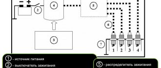
On the technical side, the ignition system is part of the engine electrical equipment complex. Structurally, it consists of the following elements:
- Battery or other power source. It supplies a low voltage of 12 volts to the network.
- Switch. When you turn the key, the switch closes and low voltage flows into the energy storage device.
- Energy storage. There are two types: inductive (a transformer-type ignition coil that converts low voltage into high voltage up to 30 thousand volts) and capacitive (capacitor).
- Energy storage and distribution control unit. Depending on the type of ignition system, this may be a chopper, a transistor switch, or an ECU (electronic control unit).
- Distributor. This unit can be mechanical or electronic. It supplies certain candles with energy at a given point in time.
- High voltage circuit wires. They supply high voltage to the electrodes of the spark plugs.
- Spark plug.
The operation of the ignition system is based on the following principle: when low-voltage voltage is supplied to the network, energy is accumulated and converted, which is then distributed among the spark plugs, on the electrodes of which a spark is formed, provoking the ignition of the air-fuel mixture.
Types of ignition systems
In the modern automotive industry, ignition systems are classified depending on the method of controlling the process. There are three main types of schemes:
- contact (contact-transistor);
- contactless (transistor);
- electronic (microprocessor).
Characteristic features of the contact system
Historically, the contact system was one of the first and today it can only be found on older car models. In such designs, the formation of high voltage occurs in a transformer coil, and its distribution to the spark plugs is carried out mechanically - by closing and opening the circuit contacts with a breaker-distributor.
Contact ignition system device
In addition to the main elements, such systems include a centrifugal ignition timing regulator, which is necessary to convert the ignition timing relative to the crankshaft speed. It consists of two weights acting on a mobile plate in contact with the cam mechanism of the breaker.
Ignition timing is a certain position of the crankshaft at which high voltage is supplied to the spark plugs. In this mode, ignition occurs until the piston reaches top dead center, which ensures the most efficient combustion of the air-fuel mixture.
Also in the contact circuits, a vacuum ignition timing regulator is used, which changes the timing angle according to the operating mode (load) of the engine. It is connected to the cavity located behind the throttle valve, and when you press the gas pedal, it changes the advance angle depending on the magnitude of the vacuum.
When the contacts are closed, a low voltage is applied to the primary winding of the coil, where energy is accumulated and at the moment the contact opens, a high voltage is formed on the secondary winding. The energy then goes to the ignition distributor and then to the corresponding spark plug.
If the load on the power unit increases, the rotation speed of the chopper-distributor shaft increases, and the weights of the centrifugal regulator diverge, changing the position of the plate. This promotes earlier opening of contacts, which increases the advance angle. When the load on the engine decreases, the reverse process occurs.
What are the differences between a contact-transistor ignition system?
The next generation of the ignition system was a contact-transistor one, which involved installing a transistor switch coil in the primary circuit. It allows you to reduce the current in the low voltage winding, which increases the service life of the contacts.
Contact-transistor ignition system
Due to the installation of a transistor, the voltage supplied to the spark plugs is 30% greater than in a classic contact system. The gap between the electrodes and, as a consequence, the length of the spark is also larger, which means that the contact area with the air-fuel mixture also increases, which contributes to its complete combustion. In a contact-transistor ignition system, the breaker acts not on the coil, but on the switch.
When you turn the key, two types of currents begin to pass through the transistor:
- management;
- main current of the primary winding.
When the contacts open, the control circuit current disappears and the transistor turns off, preventing primary current from flowing. At this moment, the magnetic field forms a high voltage on the secondary winding. To speed up the turn-off of the transistor, a pulse transformer can be installed in a contact ignition system of this type.
Operating principle of the contactless system
An evolutionary continuation of the transistor-contact system is contactless ignition. In such designs, a special pulse sensor is installed instead of a breaker. This makes it possible to increase the service life of the ignition system due to the absence of malfunctions associated with the breaker contacts.
The sensor generates low voltage electrical pulses. It comes in three types:
- Hall Sensor. The design of such a sensor includes a permanent magnet and a semiconductor wafer equipped with a microcircuit.
- Inductive. The principle of its operation is based on changing the induction value of the sensing element depending on the size of the gap between the sensor and a moving plate rotor acting on the magnetic field.
- Optic. It consists of an LED, a phototransistor and a matching chip. When light from the diode hits the phototransistor, the sensor supplies ground (minus power) to the switch. Blocking the flow of light provokes the disappearance of the current in the coil and contributes to the further formation of a spark.
Structurally, the pulse sensor is integrated into the distributor and is regulated by the engine crankshaft rotation mode. Interruption of the current in the primary winding of the ignition coil of the contactless system is also carried out by a transistor switch, but responding to sensor signals.
When the crankshaft rotates, the sensor sends voltage pulses to the switch. The latter, accordingly, generates current pulses in the low voltage winding of the coil. When no current flows, a high voltage appears on the secondary winding, which is transmitted to the distributor and then through high-voltage wires to the desired spark plug. Changing the advance angle in a contactless ignition system is also performed by centrifugal and vacuum regulators.
Electronic and microprocessor systems
The most modern system is considered to be electronic. It has no mechanical contacts, and therefore can also be called contactless. Electronic ignition is part of the engine management system.
Electronic ignition system
There are two types of electronic contactless ignition systems:
- With distributor. In such a circuit, a mechanical ignition distributor is used, which supplies high voltage to a given spark plug.
- Direct ignition. With this scheme, high voltage is supplied to the spark plug electrodes directly from the coil.
Ignition system switches
Purpose and principle of operation of the ignition system switch
In the ignition system of automobile engines, to produce a high voltage current that causes sparking on the electrodes of the spark plugs, the principle of electromagnetic induction is used - the ignition coil, which is a kind of transformer, is capable of converting the voltage of the vehicle's on-board circuit (12 V) into a voltage reaching several thousand volts. To do this, it is necessary to periodically apply and disconnect current from the primary circuit of the ignition coil, as a result of which the direct current of the on-board circuit becomes variable (cyclically varying in value from zero to 12 V and vice versa). The first engine ignition systems used devices (breakers) for these purposes that open and close electrical contacts mechanically. In principle, these devices can be called the ancestors of modern switches for automotive ignition systems.
However, mechanical (contact) switches had a number of significant shortcomings, which became more and more obvious as automobile engines developed and improved. The contacts were prone to burning, required systematic cleaning and gap adjustment, and could not “boast” of the stability of the generated impulse in terms of magnitude and duration. In addition, they had noticeable inertia, like all mechanical devices, which limited the capabilities of high-speed engines, and an insufficiently long and powerful spark was a stumbling block to increasing the compression ratio. However, such ignition systems have been used in cars for a long time, and only the advent and improvement of semiconductor devices allowed designers to make a kind of revolution in the method of switching control pulses.
At first, the designers did not abandon the use of mechanical contacts of the breaker, but they solved the problem with their electrical load, which leads to burning. A weak control current was passed through the contacts of the breaker, which was supplied to the base of a powerful transistor, which served as an amplifier of the signal entering the primary circuit of the ignition coil. This is how contact-transistor ignition systems and the first semiconductor switches appeared. Subsequently, designers of ignition systems abandoned mechanical contacts, using various magnetoelectric sensors, as well as sensors operating on the Hall effect, to form a low-power pulse. The improvement of these devices continues to this day, while modern switches of automotive ignition systems are completely different from their mechanical and even transistor “ancestors”.
The use of semiconductor and microprocessor switches in contact-transistor or contactless ignition systems allows you to obtain the following advantages:
- the current flowing through the contacts of the breaker decreases, as a result of which they practically stop burning (for a contact-transistor ignition system);
- the duration of the spark supply increases, which guarantees effective ignition of the working mixture in the engine cylinders;
- it becomes possible to significantly increase the compression ratio in the engine cylinders, as well as the crankshaft rotation speed, without compromising the reliability of spark formation.
In general, the reliability of the ignition system is increased and the complexity of its maintenance is reduced.
Manufactured switches for contact-transistor and contactless ignition systems are divided into three groups:
- switches based on discrete semiconductor components using packaged integrated circuits mounted on printed circuit boards;
- switches made using thick film technology using standard bulk and discrete components;
- switches manufactured using hybrid technology using a special solid-state microcircuit on which the main functional components of the switch are implemented.
***
Switches for contact-transistor ignition systems
Switches of contact-transistor systems and switches with a constant duty cycle of output current pulses for contactless ignition systems are functionally simple and contain a small number of semiconductor components (usually no more than four transistors). They belong to the first group. They are based on a cast aluminum housing with a ribbed outer surface to improve heat transfer. All elements of the switch are located inside the case with the exception of the output transistor, which is mounted on the case in a special pocket.
Many types of transistors (for example, npn) require insulation from the switch body, so they are mounted through a special gasket. To reduce the thermal resistance of the junction between the switch body and the gasket, thermally conductive pastes are applied, due to which the cooling of the output transistor is more intense. A terminal block is used to connect the switch to the vehicle’s on-board network and to the elements of the ignition system.
Switch TK102
In Fig. 1 shows the TK102 switch, which belongs to the first group, which is designed to work in the contact-transistor ignition system of cars with eight-cylinder engines, but can be used to work with any classic ignition distributor. Coil B114 is used as a load (W2/W1 = 235; L1 = 3.7 mH; R1 = 0.42 Ohm). To limit the primary current, an additional resistance SE107 (1.04 Ohm) is used. The TK102 switch has one powerful germanium transistor GT701A (VT1), a zener diode D817V (VD2) and a diode D7Zh (VD1), which serve to protect the power transistor VT1 from overvoltage. Choke L1 and resistor R1 are designed to speed up the process of closing transistor VT1, capacitor C1 of the primary excitation circuit of the ignition coil and capacitor C2 serve to protect the components of the switch circuit from voltage surges in the vehicle's on-board network. In the event of a switch failure (for example, if a transistor fails), the wires can be moved to the standard position, and the engine will continue to operate, allowing the driver to get to the repair site.
***
Switches for contactless ignition systems
Switches of this type are used in ignition systems, where magnetoelectric sensors, rather than mechanically controlled contacts, are used to generate a current control pulse in the primary circuit of the ignition coil.
Electronic switches of contactless ignition systems perform the following functions:
- generating an output current pulse of the required amplitude and duration supplied to the primary winding of the ignition coil (or coils) to provide a given level of high voltage and spark energy;
- ensuring the moment of spark formation in accordance with the specified edge of the control pulse arriving at the input of the switch;
- stabilization of the parameters of the output current pulse during fluctuations in the voltage of the vehicle’s on-board network and the influence of external factors.
Various switches can perform additional functions:
- stabilization of power supply and protection against overvoltage pulses in the vehicle’s on-board network in abnormal modes of a microswitch operating on the Hall effect;
- limiting the amplitude of the secondary voltage pulse in abnormal modes (for example, in open circuit mode);
- preventing the flow of primary current through the primary winding of the ignition coil when the ignition switch is on and the engine is not running.
The input terminals of the switch receive control pulses generated by a non-contact sensor of the angular position of the engine crankshaft or an electronic voltage regulator - a collector. The output (load) of the commutator is the primary winding of the ignition coil (or coils). In the case when the commutator serves two or more coils, it serves as a distributor of high-voltage pulses across the engine cylinders.
Numerous switches for contactless ignition systems can be divided into two groups:
- switches with a constant duty cycle of the output primary current pulse (duty factor is the ratio of the pulse repetition period to their duration), independent of the engine speed;
- switches with a standardized duty cycle of the output current pulse.
Common to both groups of switches is the presence in the output circuit of a powerful output transistor capable of switching currents with an amplitude of up to 10 A in the inductive load of the collector.
Switch 13.3734
An example of switches for contactless ignition systems is switch 13.3734, developed on the basis of the first serial domestic switch TK200 “Iskra”. The switch is designed to work together with a contactless magnetoelectric sensor, a B116 ignition coil and an additional resistance of 14.379.
Switch 13.3734 (Fig. 2) contains an output resistor VT3 (KT848A), a pre-amplification stage on transistor VT2 (KT630B) and resistor R7, a sensor signal conditioner on transistor VT1 (KT630B) and elements R1-R8, C1, VD1, VD2.
There is a positive feedback between the output and input of the commutator (R10, C7), ensuring stable operation of the commutator at the starting speeds of the distributor shaft (20...30 rpm). Circuit R3-C1 serves to reduce the electrical displacement of the ignition timing depending on the speed of the sensor shaft.
The switch also contains circuit elements (C2-C4, VD3, VD4, R8) and output transistor protection circuits (C5, C6, R9). The switch is made on a printed circuit board on which low-power circuit elements are mounted. The board is installed in a finned cast duralumin housing, where the power elements are located.
***
Switches with normalized duty cycle of output current pulses
Switch 36.3734
The first domestic switch 36.3734 with a standardized duty cycle of output current pulses, used on the VAZ-2108 car, is also made using discrete technology and is designed to work with a contactless sensor operating on the Hall effect. The load used is ignition coil 27.3705 (W2/W1 = 85; L1 = 3.8 mH; R1 = 0.5 Ohm).
The 36.3734 switch implements software control of the time of energy accumulation in the primary winding of the ignition coil, active limitation of the primary current level (8...9 A), limitation of the amplitude of the primary voltage pulse (350...380 V), spark-free shutdown of the primary current when the engine is stopped (Totkl = 1 ,53 s). The latter is designed to smoothly turn off the switching transistor to prevent sparking when the engine stops when the ignition coil remains energized.
In the 36.3734 switch, the main functional units are made on operational amplifiers DA1.1-DA1.4, which are components of the K1401UD1 microcircuit. Based on amplifiers DA12 and DA13, an integrator and comparator (normalization of the pulse duty cycle) of the output current are implemented. The DA1.1 amplifier contains a spark-free current shutdown circuit, and the DA1.4 amplifier contains a comparator for limiting the amplitude of the output current. A Darlington transistor KT848A is used as the output transistor. Structurally, the switch is a printed circuit board on which the radio components of the circuit are located, with the exception of the output transistor VT4, the protective diode VD7 and the zener diode VD4 of the supply voltage limiter, which are mounted on the switch body. To connect the switch to a contactless Hall sensor, to the ignition coil and power source, a removable contact connector is used.
***
Switch 42.3734
The ideas of software control of the duty cycle of output current pulses are also implemented in ignition systems with low-voltage distribution of high-voltage voltage pulses. In this case, the switches are usually made of two channels - serving two ignition coils.
The electrical circuit of the discrete two-channel switch 42.3734 is developed on the basis of the electrical circuit of the switch 36.3734. The main difference is the presence of two output stages (VT4, VT6 and VT5, VT7) that control the operation of output transistors VT8 and VT9. In turn, the output stages control the switch channels using a key stage on transistor VT2 (KT342A). The switch circuit is also equipped with a signal conditioning device for controlling the tachometer (VD14, VD15, R53, R54).
The 42.3734 switch is made on two printed circuit boards (Fig. 3): the control board A1, on which the operational part of the switch is located, and the power board A2 with elements of the output stages and output transistors. Moreover, the latter are mounted on an additional heat sink. The boards are installed in the case, one above the other.
***
Advantages and disadvantages of different types of switches
The disadvantages of switches of the first group include large overall dimensions and weight, as well as, in large-scale production, low manufacturability and insufficient reliability due to the large number of radio components.
A significant reduction in weight and size parameters can be achieved by manufacturing switches using thick-film technology using standard unpackaged components. However, this technology is relatively expensive and labor-intensive, and therefore has not been widely used in industrial large-scale production of switches.
The best indicators in terms of labor intensity and manufacturability of production, as well as reliability, are possessed by switches of the third group, which contain a special microcircuit where the main functional units are located: a duty cycle normalization circuit with adaptation to the output current level, a spark-free current shutdown circuit, a current limiting device, etc. Hybrid thick-film technology is used to implement the power part of the switch circuit with elements of protection against pulse overloads along the power circuit. An example of the use of this technology is the 0.227.100.103 switch (Germany), the diagram of which is shown in Fig. 4.
The circuit includes the following elements: unpackaged output transistor VT1; specialized microcircuit DA1 (MA 7355) with miniature hanging capacitors C2-C5, which performs the main functions of the switch; body diode VD1, zener diode VD2, miniature capacitor C1 and thick-film resistors R3, R4, which perform the functions of protection against surge voltages in the on-board network and reversal of battery polarity.
There are also thick film resistors that serve to change and adjust the required levels of primary current (R6, R7, R10) and primary voltage (R8, R9). The protection circuit of the output transistor is made on discrete elements C7 and R11.
The production of similar switches has been launched, made in the form of a large hybrid integrated circuit (LHC), which is a thick-film micro-assembly of the operating part and a micro-assembly of the power part of the switch, mounted on a copper base SA made of polymer material. Moreover, the housing is made integral with the seven-pin connector. The housing is sealed with an adhesive lid. The substrates of thick-film assemblies are aluminum oxide ceramics (Al2O3). The appearance of single-channel and dual-channel switches is shown in Fig. 5.
With the development of digital and microprocessor technology and the development of complex engine control systems, a transistor switch, while maintaining its functional purpose, in design terms may not have the outline of an independent product, being combined into a single design with a digital controller. The next step towards integrating the electronic unit is to transfer the function of normalizing the duty cycle of the output current pulse to the controller circuit. In this case, the switch module implements the functions of distributing high-voltage pulses, limiting current and primary voltage, and issuing a feedback signal about the current level in the ignition coil.
***
The switch is. Switch diagram. How to check the ignition switch
The switch is an electronic component to ensure the operation of a contactless ignition system. It is transitional between contact and microprocessor. The latter, the most advanced, allows you to control the torque using data read from sensors - oxygen, speed, engine speed and others. But there are still many cars on the roads that have both contact breakers and contactless ones. Therefore, for maintenance and diagnostics, you need to know the purpose of all elements, as well as troubleshooting methods and their main symptoms. Before testing the switch, review all parts carefully.
Signs of a faulty switch: how to check the switch yourself.
Purpose and design features of the switch.
A switch is one of the elements of a car's electrical equipment. His task
– ensuring normal operation of the contactless ignition system. The assembly is fastened in the engine compartment.
The device is different
reliability, ability to withstand severe vibrations and shock loads. This is very important, because the switch housing contains sensitive electronics.
At the heart of the VAZ switch
– standard L 497 microcircuit, which controls an “NPN” type transistor.
>Scheme feature
– possibility of programming by the user and setting the required delay coefficient. Starting a cold engine directly depends on the correctness of this indicator.
Thanks to precise settings
, you can speed up the crankshaft rotation speed (while eliminating failures in operation) and guarantee high-quality traction of the power unit.
The main parameters of the switch device include:
Voltage range – from 6 to 16 Volts; operating voltage level – 13.5 Volts; ensuring an uninterrupted spark when the crankshaft rotates in the range from 20 to 7000 rpm; switching current – from 7.5 to 8.5 A.
Signs of a faulty switch.
One of the main symptoms of a faulty switch is loss of spark.
. The engine starts hard and stalls from time to time, causing interruptions in operation.
But don't rush to replace it
- it is important to verify the reason, because
loss of spark can occur for a number of reasons
- failure of the Hall sensor, rupture of the timing belt, malfunction of the ignition coil, poor contact in the distributor cap, problems in the wiring, and so on.
If diagnostics of other nodes does not produce results
, then we can move on to our “hero”. But how to check the switch, since the device has a very complex design?
How to check the switch yourself.
Most car enthusiasts don’t bother with diagnostics and simply install a new unit. This method has its advantages.
Firstly
, there is no need to waste time checking - just install a new part.
Secondly
, you can immediately determine whether this is the reason or not. In fact, there is no need to be afraid of the work, because checking the switch takes a few minutes.
So, to carry out work at home, a test lamp (nominal voltage should be 12 Volts) and a standard set of keys are enough.
With their help, you can verify the presence or absence of pulses, and later make a decision about the serviceability of the device itself.
Algorithm for checking the switch:
To begin work, it is advisable to disconnect the battery so as not to accidentally short-circuit the wiring that you will unscrew.
Using an eight-point wrench, unscrew the nut and remove the wiring from the ignition coil marked “K”. This wire is easy to recognize - it is brownish in color and goes to the terminal labeled one on the switch;
Connect this wire through a control light to terminal “K” on the ignition coil, and then connect the battery;
Turn on the engine starter and observe the lamp's actions. If it blinks, then the switch is working. If the light bulb does not show any signs of life, then the only way out is to replace the device.
If there are doubts about the serviceability of a part, the check should be carried out on a special stand (there is always one at the service station).
In this case, it is possible not only to determine whether the product is working, but also to measure the duration of the pulses.
When the first suspicions appear, you should not immediately change the switch or spend money on a specialist. You are quite capable of doing the job yourself.
Moreover, now you know how to check the switch on the VAZ 2109 and other models of the domestic brand. All that remains is to allocate time and prepare a minimum set of tools. Have a good trip and of course no breakdowns.
Contactless ignition system
In total, there are three huge groups of systems - contact, contactless, microprocessor. The first is divided into two subgroups - contact and using a transistor operating in switch mode. Transistors are also used in the design of a contactless ignition system. This scheme began to be actively used in the early 80s of the last century. And it has a number of advantages, which will be discussed below. The switch circuit is simple; it can be implemented both on transistors and on a controller.
But the contactless ignition system also has many disadvantages when compared with a microprocessor one. The latter allows you to control almost all engine parameters. BSZ does not allow this; it also cannot be used normally on injection engines. The reason for the obsolescence of the contactless system lies not only in the development of electronics and the automotive industry, but also in the adoption of stringent measures to ensure the environmental friendliness of internal combustion engines. Unfortunately, only microprocessor control can reduce the amount of harmful substances in the exhaust.
Advantages of contactless systems
For an ignorant car enthusiast, the main argument in favor of BSZ is the fact that at the moment not a single manufacturer produces cars with a contact-cam spark generation system. Foreign brands abandoned it in the distant 80s of the last century, and in the Russian Federation mechanical ignition lasted until the 90s. The reasons for the refusal are quite clear:
- sparks constantly flashed across the contacts, causing them to burn and require frequent cleaning;
- the contact group wore out quite quickly, on average it was enough for 15-20 thousand kilometers, after which the element had to be replaced;
- the wear of the bearing on which the contacts were located made itself felt, which caused unstable operation of the power unit;
- the springs of the balance weights were stretched.
All of the listed malfunctions appeared one by one, haunting the owner of the “classic” Zhiguli. Due to an imperfect design, the spark power of the spark plugs was constantly decreasing, engine performance was deteriorating, and fuel consumption was increasing. New BSZ systems are free of such disadvantages; they are characterized by durability and stable sparking. The spark power also increased, since the output pulse voltage increased from 16-18 kV to 24 kV, which contributes to better ignition of the fuel.
At first, the weak point of domestic contactless systems was considered to be the switch, which quickly failed and could not be repaired. But later it was improved and the reliability of the BSZ increased.
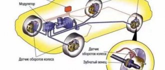
Main elements of the system
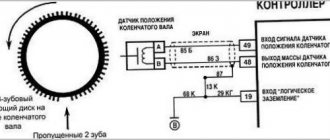
Of course, the first thing to mention is the spark plugs. They are installed in the cylinder head, the electrodes come out from the inside. These are the elements that allow the air-fuel mixture to ignite. But with the help of spark plugs alone, the engine will not be able to run. It is necessary to monitor the position of the crankshaft in order to know in what position the pistons are in the cylinders.
For this purpose, an inductive sensor operating on the Hall effect is used. It is part of the design of another element - the ignition distributor. The sensor produces a pulse that is sent to the switch. This device allows you to amplify a weak signal to a voltage of 12 volts, and then apply it to a coil. A coil is nothing more than a simple transformer (step-up). Its secondary winding has a greater number of turns than the primary. Due to this, the voltage increases and the current decreases. The voltage in the BSZ is supplied to the spark plugs at a value of 30-35 kV (depending on the car model).
How is BSZ better than contact?
Having carefully read the previous section, you can see that the system uses an inductive non-contact Hall sensor. The advantage is obvious - there is no friction and commutation. For comparison, look at the contact system. In it, the breaker switches the voltage, the value of which is 12 Volts. Whatever one may say, the metal contacts are constantly in contact with each other, gradually wear out, and become covered with soot.
For these reasons, it is necessary to constantly monitor the breaker, adjust the gap, and carry out timely replacement. BSZ is devoid of these shortcomings, therefore, without third-party intervention, the system operates much longer. The Hall sensor fails very rarely, as does the switch. This increases the reliability of the system, but precautions must also be taken, in particular, the connection of the switch to the body must be as tight as possible to ensure effective heat exchange. In addition, BSZ allows you to improve engine performance, increase, albeit slightly, its power, along with increasing reliability.
Existing types of switches
There are two main types of devices: AC CDI and DC CDI. The first switches were small and simple, using a high-voltage generator in their circuitry. The latter are more common, equipped with four contact groups with minus and plus, as well as separate outputs for the coil and Hall sensor. But the latter function only in the presence of high voltage supplied from an external source.
Switches are also usually classified according to their functional features:
- traditional or stock devices that strictly correspond to the parameters of the car - as a rule, they are installed from the factory;
- sports - they have the ability to increase the upper limit of the number of revolutions of the internal combustion engine, however, this type is the lot of experienced specialists and has the risk of accidents;
- with the ability to adjust the phases of the UZ - an excellent option when you need to equalize the torque of the power plant, improve acceleration characteristics and stabilize engine operation at different speeds.
Of course, switches are usually divided into main types.
Electronic
This type of switch is also called a microprocessor switch with transit keys. It is used to control the converter voltage and reduces the load on the connections, thereby increasing the current capacity.
Advantages of the electronic system:
- possibility of better filling of internal combustion engine cylinders;
- efficient engine output at all speeds.
Hybrid
These systems additionally use a mechanical part - a cam distributor. The electronics are represented by the switch itself and the coil. The unit is very reliable, economical and convenient. For example, if a switch fails, you can switch to an old converter with a slider.
Contactless
A group with transistors, widely used since the early eighties. It replaced the antediluvian classical contact systems. At one time it was considered the most effective, since its performance indicators were much higher than those of other switches.
Dual channel
The same contactless system, but significantly modernized. For example, a conventional BSZ has the same disadvantages of a KSZ - loss of spark energy, instability of idle speed, limitation on adjustment of the SPD, high sensitivity to pollution and humidity. A two-channel system or DBSZ eliminates these disadvantages from the ignition system, providing even higher spark energy through the use of additional coils. Also, problematic moving elements - a slider and a coal - are not used here, and the lid serves only as a protective element. Therefore, it is not subject to burnout.
Interestingly, two-channel ignition was used before. This was implemented on export VAZ-21083. However, switches of this type, also called dual-circuit switches, were not widely used due to the poor quality of the electronics of that time.
One more nuance regarding switches. They may have different outputs. Those with the default number “1” are extremely dangerous for the ignition coils at the moment they experience malfunctions. But the advantage of such devices is that standard converters for contact ignition can be integrated with them.
For the second types of switches, in which output “0” is used by default, conventional coils are completely unsuitable. They will get very hot, or the spark will not flow properly. Such a switch includes, for example, the model for BTsZ 131.3734.
How does a switch work?
Essentially, a switch is a simple signal amplifier. It can even be compared to a Darlington assembly, which is used in microcontroller technology to convert a weak signal from an output port to the required level. The basis of this assembly is field-effect transistors operating in switch mode. An operating voltage is applied to them, a signal is sent to the control terminal, which is amplified and removed from the collector.
The ignition switch has an almost similar operating scheme. Only the signal from the Hall sensor is used. It has three outputs - control, common, plus power. When a metal plate appears in the sensor area, a current is generated, which is supplied to the input of the switch. Next, the signal is amplified and supplied to the primary winding of the coil. The entire system is powered only after the ignition is turned on (after turning the key).
Operating principle of a car ignition switch
The signal from the rotation sensors is very weak and for use in control systems, it must be generated and amplified. In addition, various types of sensors provide signals of an analog type or in a form that is inconvenient for use. To control the current of the primary winding of the ignition coil, electronic devices have been developed that allow switching (switching) at high speed. The signal from the switch is supplied to the primary winding of the ignition coil.
Rice. Photo of the switch and oscillogram of control pulses.
Rice. Photo of the switch and oscillogram of control pulses.
The switch can also be two-channel, controlling two ignition coils at once.
Rice. Photo of the switch and oscillogram of ECU signals.
The switch can also perform a more complex role. Let's consider an example on the control diagram of a FORD Scorpio EEC 4. The figure shows a diagram of such an ignition system. Such a device can even be called an ignition module. It is located on the ignition distributor. The module receives a PIP (Profile Ignition Pickup) signal from the Hall sensor located in the distributor.
Rice. Diagram of the ignition system of a FORD car.
It is processed and transmitted to the engine ECU in the form of a frequency signal of 10-15 Hz. The ECU recalculates the correction factors and returns the SPOUT (SPark OUTput) signal back to the TFI module. The frequency of such a signal is 10-15 Hz, but the shape of the pulses is different. At idle, the PIP signal has a frequency of 25-35 Hz, and the SPOUT signal has a frequency of 40-45 Hz, which controls the output stage of the switch. Oscillograms of the input and output signals of the TFI module are shown in the figure.
Rice. Oscillograms at 3000 rpm.
Basic Switch Elements
The switch circuit is quite simple, but making this unit yourself is pointless, since buying a ready-made version will be much easier. Installation must be carried out as competently as possible, otherwise the device will not operate correctly. In addition, when using transistors, you need to carefully select them according to their parameters, and for this you need to have high-quality measuring equipment. Unfortunately, for two identical semiconductors, the spread of characteristics can be very large. And this affects the operation of the device.
The VAZ switch, designated 76.3734, consists of one main element - the L497 controller. It is designed specifically for use in contactless ignition systems. The domestic analogue of this controller is KR1055HP2. Their parameters are almost identical, which allows you to use any of the controllers. In addition, this chip allows you to connect a tachometer located on the dashboard of the car. But you can also use a simpler circuit, which is an amplifier unit of two stages. True, the reliability of such a device is much lower.
Replacing the switch on a contactless ignition system
An unscheduled replacement of the switch on the “seven” is carried out when it is impossible to operate the device due to a breakdown. Carrying out work of this kind is very simple; only initial knowledge in plumbing and electrical engineering and the availability of the necessary tools (a set of heads with a wrench and a ratchet) and a replaceable device are required.
This replacement of the VAZ 2106 ignition switch occurs in the following order:
- We disconnect the wiring from the “six” switch, which connects it to the breaker - distributor with a plug:
- We unscrew 2 body fasteners of the VAZ 2106 switch at different edges of the gadget; for this it is better to use a set of sockets with a ratchet and a wrench-extension:
- We dismantle the ignition switch to check it, and if necessary, replace it;
- Installation of this gadget follows the reverse principle.
Connection diagram for electronic ignition elements of VAZ 2107
Connecting the switch
Cases vary, and it is possible that you will have to change the wiring. Therefore, you will need to take into account the purpose of all pins on the switch plug. This will allow the connection to be made correctly, and there will be no risk of damaging it. The first pin of the switch is the output. In other words, the amplified signal is removed from it. It must be connected to the terminal of the “K” coil. The second contact is connected to ground - the negative of the battery.
All three wires from the Hall sensor go to the VAZ switch. Moreover, the signal wire is connected to the sixth terminal of the switch. The fifth is the power output (the voltage on it is stable 12 Volts). The third output of the switch is ground (minus power). The third is connected inside the block to the second. But between the fourth, which is supplied with power from the battery, and the fifth there is a constant resistance and a voltage stabilizer.
How to check
There is nothing complicated in this procedure. The easiest way is to use a known-good node, since you can check the switch this way in literally a matter of minutes. But if there is none, and you need to determine exactly whether the fault is in the coil or in the switch, it is wiser to use other methods. You will need a simple incandescent lamp. If you don’t know where to get it, then unscrew it from the interior lamp or from the side lights.
Connect one terminal of the lamp to the negative of the battery. Connect the second one to pin “1” of the switch. This is the same pin from which the amplified signal is removed. If the lamp lights up, then the device is working properly. A more advanced testing method is carried out using an oscilloscope. On the screen you can see the magnitude and shape of the signal, and also compare it with the reference one.
Test method
First, you need to check the presence of supply voltage at the terminals of the switch (not only with a voltmeter, but also with a load). Make sure there is a correct input signal to the switch (oscillogram). The output signal from the switch is checked with a car oscilloscope or a regular car light bulb. If the signal increases from 0 to the supply voltage, then the light bulb is connected between the “+” and the signal terminal (disconnect from the ignition coil). The light should flash when the engine is rotated by the starter.
It must be remembered that switches used with generator-type sensors cannot be used in systems with a Hall sensor and vice versa.
Ignition settings
When setting up the ignition, you will need to do the most important thing - install the shafts according to the marks so that the gas distribution functions synchronously with the operation of the piston group. This is the first thing you should do before you start adjusting the ignition. It is worth noting that there should not be any particular difficulties during setup, especially on VAZ 2108-21099 cars. The thing is that the ignition distributor on the engines of these machines can only be installed in one position. Moreover, the ignition switch does not undergo any settings during this procedure, since it does not have any.
The distributor body rotates around its axis to make more precise adjustments. And this turns out to be enough. To accurately set the torque, you can use a simple circuit that uses a simple LED as an indicator. The Hall sensor is disconnected from the system, and positive power is supplied to its negative terminal. An LED is switched on between “+” and the signal LED, and a 2 kOhm resistance is connected in series with it to reduce the voltage. But the plus of the Hall sensor is connected to ground. Now all that remains is to slowly rotate the distributor housing. The moment when the diode lights up will be the desired one.
How to determine if the ignition switch is faulty
The introduction of an ignition switch into the design of a car, especially on domestic cars of the VAZ family, made it possible to increase their reliability. And although the first production car with an electronic ignition system was the VAZ 2108, similar devices began to be installed on many other cars, primarily classics. However, the use of such a rather complex product has led to the fact that finding a malfunction, as well as checking and repairing the switch, has become possible for the most part only in specialized centers. External signs indicating that a malfunction has occurred may include:
- the engine does not start, there is no spark at the spark plugs;
- the engine starts but stalls after a few minutes;
- The motor is unstable; if the switch is replaced with a known good one, the defect is eliminated.
The easiest way to identify a malfunction and test a switch, as already noted, is to install a known-good one. Due to the rather low quality of the switches supplied for the VAZ family of cars, including the VAZ 2108, drivers have to carry additional switches with them to replace the failed one. However, there is also an indirect evaluation principle that allows you to check the performance of the product and identify its malfunction.
To do this, you can use the readings of the voltmeter in the instrument cluster. You need to turn on the ignition, and the needle will be in the middle of the scale, and a little later it will swing to the right (due to the power supply to the coil being turned off when the engine is not running). This arrow behavior indicates that there is no fault in the switch. In the event that there is no voltmeter, a test lamp is required to check the ignition. One end of it is connected to ground, the other to the output of the coil connected to terminal 1 of the switch. If you turn on the ignition, then if the switch is working properly, after a while the lamp will burn brighter.
However, in some cases, the ignition malfunction is not related to a switch failure. It is necessary to check the condition of the wires, first of all, contact with ground and the condition of the connectors. It is also necessary to check the Hall sensor.
The appearance of a voltage switch in the design of a car, including the domestic VAZ 2108, was a natural result of the development of the ignition system. Its further improvement was the use of first dual-channel and then multi-channel switches to improve operating efficiency. » alt=»»>
Post Views: 3
conclusions
Many advantages are provided by such a simple unit in a contactless ignition system as a switch. This includes an increase in power, even if only slightly, a reduction in fuel consumption, and a significant improvement in the engine in terms of reliability. And most importantly, there is no need for constant monitoring and timely adjustment of the system. The modern driver does not want to repair a car, he needs a means of transportation. Moreover, it is reliable and will not let you down at the most crucial moment. Regardless of which switch is used in the BSZ, its efficiency is much higher than that of a contact breaker.
Basic principles
The correct conditions for the ignition system, or rather, the basic conditions, are:
- The spark must appear in the correct cylinder, in accordance with the firing order of the cylinders.
- The spark must occur in a timely manner, at the right moment and with the required ignition timing.
- It must be guaranteed to ignite the mixture.
- Reliability
As you understand, such a system may also experience problems, for example, misfiring, detonation, and difficulties starting the engine.
In today's world there are several types of ignition systems for cars, contact, contactless and electronic. These systems have common features, for example, the absence of an ignition distributor, which long ago gave way to a coil.
In a contact ignition system, the accumulation and distribution of electrical energy among the cylinders is controlled by a mechanical device - a breaker-distributor. A further development of the contact ignition system is the contact transistor ignition system, in the primary circuit of the ignition coil of which a transistor switch is used.
Unlike a contact system, a contactless ignition system uses a transistor switch that interacts with a contactless pulse sensor to control energy accumulation. The transistor switch in this system acts as a breaker. The distribution of high voltage current is carried out by a mechanical distributor.
The electronic ignition system uses an electronic control unit, which controls the process of accumulation and distribution of electrical energy. In early electronic ignition system designs, the electronic unit simultaneously controlled the ignition system and the fuel injection system (the so-called combined injection and ignition system).
Device
The principle of operation of the ignition system is the accumulation and conversion of the low voltage (12V) ignition coil of the vehicle's electrical network into high voltage (up to 30,000V), distribution and transmission of high voltage to the corresponding spark plug and the formation of a spark at the right moment on the spark plug. The following stages can be distinguished in the operation of the ignition system: accumulation of electrical energy, energy conversion, energy distribution over the spark plugs, spark formation, ignition of the fuel-air mixture.
The mechanical breaker directly controls the accumulation process (primary circuit) and is responsible for closing/opening the power supply to the primary winding. The breaker contacts can be seen by looking under the distributor cap. The plastic spring of the movable contact presses it against the fixed contact. They are opened only for a short period of time, namely, at the moment when the advancing cam of the drive roller exerts pressure on the movable contact hammer.
A capacitor is connected to the contacts, which prevents them from burning. The electrical discharge is absorbed and sparking is reduced. In parallel, a low reverse current voltage is created in the circuit, which has a positive effect on the disappearance of the magnetic field.
Switch VAZ 2108, 2109, 21099
The contactless ignition system of VAZ 2108, 21081, 21083, 2109, 21091, 21093, 21099 cars uses an electronic switch.
Switch for contactless ignition system of carburetor engine of VAZ 2108, 2109, 21099 cars
Switch Purpose
The switch is designed to interrupt the electric current flowing through the primary winding of the ignition coil, according to a signal from the Hall sensor. The interruption results in a high voltage current flowing to the spark plugs.
In addition, the switch automatically regulates the period of current accumulation in the ignition coil depending on the crankshaft speed. It also turns off the current supply through the ignition coil when the engine is not running but the ignition is on.
Switch device
Inside the switch there are powerful transistors designed to interrupt the electrical current. As well as devices for automatic accumulation of current in the ignition coil and automatic locking of the transistor when the engine is stopped.
Operating principle of the switch
When the ignition system is operating, pulses from the Hall sensor installed in the distributor are sent to terminal “6” of the switch and then through it to the primary winding of the ignition coil. When the current in the primary winding of the ignition coil is interrupted, the magnetic field in it sharply contracts and induces an EMF of 22-25 kW, which gives a spark on the spark plugs sufficient to ignite the fuel mixture.
Switch connection diagram
Connection diagram for the switch of the contactless ignition system of the carburetor engine of VAZ cars VAZ 2108, 2109, 21099
Switch problems
"The switch is on"
Car engine does not start
The engine “troits” - interruptions in sparking
See “Checking the switch of VAZ 2108, 2109, 21099”,
“The carburetor engine starts and stalls: reasons related to the ignition system.”
Applicability of the switch on VAZ 2108, 2109, 21099 cars
In the contactless ignition system of VAZ 2108, 2109, 21099 cars, the following switches are used: 36.3734, 3620.3734, 76.3734, 133.3774-01, RT1903, PZE1022 and their analogues from different manufacturers.
Notes and additions
— When replacing or checking the switch, it is prohibited to disconnect the wire block from it with the ignition on, in order to avoid damage to its electronic filling.
Twokarburators VK - More information on the topic in our VKontakte group, on Facebook Twokarburators FS and on Odnoklassniki - Twokarburators OK
More articles on the ignition system of VAZ 2108, 2109, 21099 cars
— Distributor VAZ 2108, 2109, 21099 principle of operation
— Signs of a Hall sensor malfunction
— What is the difference between spark plugs for contact and contactless ignition systems?
— What is the difference between hot and cold spark plugs?
— Checking the spark on the spark plugs
— The ignition coil is heating up, why?
— The switch is heating up, why?