Ignition system maintenance
Military Encyclopedia - historical and archival military-patriotic portal
home☆Soviet military encyclopedia☆military equipment☆military science☆military review☆history of weapons☆forum
military equipment ☆ articles on the VAT device ☆
During TO-1, the surfaces of the ignition devices are cleaned of dust and dirt, and the tightness of all connectors of the shielding hoses of high-voltage wires and connectors of low-voltage wires is checked.
During TO-2, lubricate the shaft and bushing of the ignition distributor rotor; inspect the distributor and check the ignition installation; turn the spark plugs out, check and adjust the gap between their electrodes; wipe the removable parts of the spark plugs, check the condition of the wire insulation and their fastening.
During the fourth TO-2, the ignition distributor is removed, inspected and eliminated.
At a service station, the ignition system is checked to avoid difficult starting of a cold engine in winter.
The distributor shaft is lubricated through a cap-type oiler screwed into its body. For this purpose, turn the oiler 1/2…1 turn; If required, put Litol-24 lubricant in the oiler. The rotor bushing is lubricated with 4...5 drops of engine oil.
The gap between the electrodes of the spark plugs is checked using a special round probe. Setting the normal gap is done by bending the side electrode.
When removing the ignition distributor from the engine, it is disassembled, all elements are inspected, cleaned of dirt and dust, assembled and its operation is checked on a special stand.
Rice. 76. Ignition installation: 1 - ignition installation indicator; 2 — crankshaft pulley; 3-risk, on the flange of the distributor drive housing; 4 — upper flange of the distributor drive housing; 5 — groove on the distributor drive shaft: 6 — lower flange of the distributor housing.
The ignition installation is performed if the distributor is removed from the engine or if the ignition timing is violated. The procedure for performing this work is as follows:
- set the piston of the first cylinder to a position 4.5 before TDC. To do this, unscrew the spark plug, close the hole with a paper plug and turn the crankshaft until the plug is pushed out, after which a mark is placed on the crankshaft pulley (Fig. 76) between numbers 3 and 6 on the ignition setting indicator scale;
- install groove 5 on the upper end of the distributor shaft so that it is in line with disks 3 on the upper flange of the distributor drive housing and is shifted to the left and up from the center of the shaft;
- insert the distributor drive into the block socket, first ensuring the alignment of the bolt holes in the lower flange of the drive housing and the threaded holes in the block;
- in the distributor drive installed in place, the shaft groove is placed parallel to the axis connecting the holes on the upper flange of the drive housing;
- turn the crankshaft two turns; the mark on the pulley should be between numbers 3 and 6 on the ignition indicator; put the distributor in place so that the octane corrector plates are directed upward, remove the screen cover, screen and distributor cover and by turning the distributor body, align the red marks on the rotor and stator of the pulse sensor, while pressing the rotor counterclockwise to select the gaps. In this position, secure the distributor body and tighten the bolt securing the upper plate of the octane corrector;
- install the distributor cap and screen, check the correct installation of the wires connected to the distributor cap in accordance with the operating order of the cylinders (1-5-4-2-6-3-7-8).
Check the correct installation of the ignition with mileage. When driving in direct gear at a speed of 30 km/h on a flat road, sharply press the throttle pedal. If at the same time the speed increases to 50 km/h and weak, quickly disappearing detonation knocks are heard, then the ignition is set correctly. If there are no knocks, then the ignition timing is increased, if the knocks are strong, they are reduced. The ignition angle is adjusted using an octane corrector. Before driving the car, the engine must be warmed up to 75-80°.
Tags: maintenance ☆ car device ☆ car electrical equipment ☆
| Design and operation of ignition system devices < Prev. | Track. > Ignition system malfunctions |
Only high-quality inexpensive furniture made in Russia. All furniture is checked by specialists.
- Contacts:
- +7
- from 9:00 to 20:00 daily
- Moscow
Military Encyclopedia. Map of site.
Main signs of a faulty ignition system
The main external sign of a faulty ignition system is engine failure or unstable operation. Also, problems with ignition may be indicated by a decrease in engine power, as well as increased fuel consumption. It is worth noting that problems in the ignition system are often associated with defects in the vehicle’s fuel system or malfunctions of the injection system. That is why, when diagnosing a car and identifying the causes of a breakdown, it is necessary to carry out a comprehensive check of all the listed systems.
Why does the car stall while driving?
Repairing the car engine power supply system
As for the most common malfunctions that many drivers of VAZ cars encounter, the list of common reasons includes those that lead to the fact that the domestic car 2106 stalls while driving. Let's look at them in detail.
- Low quality of fuel used. This is where experts recommend starting to look for the source of the problem. If, when draining the old fuel and replacing it with a new one, you are lucky and the car starts, you can confidently say that you should not skimp on the quality of gasoline for your car.
- Candles. Often, after changing the fuel and the problem persists, that is, the VAZ still does not start, suspicion falls on the spark plugs. You should check their condition after they are unscrewed and, if necessary, replace them with new ones.
- Fuel filter. Very often, a clogged filter can provoke interruptions in the fuel supply, as a result of which the VAZ 2106 stalls while driving. To eliminate the problem, it is enough to replace the fuel filter.
- Problems with the air filter are solved using the same method as with the fuel filter. A clogged filter does not allow air to pass through, which leads to engine pressure, that is, a drop in power. This way, the combustion process of the mixture will not take place, and as a result, the engine will stall.
- The problem is the fuel pump. A faulty fuel pump causes the VAZ 2106 to stall or not start at all. Treatment is checking the pump followed by repair or replacement.
- Battery: oxidation or poor terminal contact. The terminals should be checked, and then the battery should be cleaned or replaced.
- If the engine stalls while driving and won't start again, the cause may be the generator, which is not providing a charge. And since the car is powered only by the battery and, as you know, it doesn’t last long, the car starts working on the battery until it is completely empty.
- In modern brands, the cause of breakdown can be faulty electrical equipment. With such a problem, it is better to immediately contact specialists, because without experience and knowledge, you can replace half a car, but not get rid of the problem.
Every car owner who drives classic cars from AvtoVAZ constantly faces some problems. It often happens that you really need to drive right now, but the car won’t start. VAZ 2106 is no exception. There are several typical reasons for this behavior. Today we will look at the main problems that can occur with the “six”.
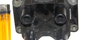
Breaker-distributor
Vehicle power system design
The main faults are:
- wear and burning of contacts
- decrease in spring elasticity
- wear of the textolite bushing and heel of the breaker lever
- cracks or through spark breakdown of parts (cover, rotor)
Burnt contacts are cleaned with glass sandpaper or a special needle file, followed by wiping with a rag soaked in gasoline. If the contact height is less than 0.6 mm, replace the breaker lever or contact stand assembly. Instead of worn contacts, new ones are soldered using PSr-70 solder.
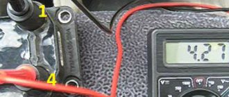
The spring tension is checked using a dynamometer. The spring force along the axis of the contacts at the moment of their rupture must be at least 4.9 N. The moment of contact rupture is determined by a test lamp. If the spring weakens, the breaker lever assembly is replaced.
In ignition timing regulators, damaged springs, diaphragms, fitting gaskets, and textolite parts are replaced with new ones.
In the assembled breaker-distributor, the roller should rotate easily, its longitudinal movement should not exceed 0.25 mm. The assembled breaker-distributor is adjusted and tested on the KI-968 stand. It is connected to the induction coil and battery of the stand. The average value of the current passing through the contacts of the breaker, other things being equal, depends on the angle of the closed state of the contacts, i.e., on the angle of rotation of the breaker cam, within which the contacts are in the closed state. At the stand it is controlled using the IUC device. The angle is checked at a cam rotation speed of 1500 rpm and adjusted by changing the gap between the contacts.
The suitability of the capacitor is determined by comparison with a standard one in terms of sparking quality. If, when the capacitor under test is connected to the circuit, the intensity of sparking decreases, the capacitor is faulty.
The assembled switch-distributor is checked for uninterrupted spark formation. With a gradual increase in the rotation speed of the distributor shaft to the values specified by the technical requirements, there should be no interruptions in spark formation noticeable to the eye or ear on three-electrode spark gaps with a spark gap of 7-10 mm.
The correct alternation of spark formation in the distributor is checked by applying high voltage from the induction coil to the neon lamp of the stand's synchronoscope. The angle of alternation of lamp flashes, measured on a graduated disk at a distributor roller speed of 100-150 rpm, should be 90° for cams with four protrusions, 60° for cams with six and 45° for cams with eight protrusions. The deviation should not exceed ±1°. Large unevenness indicates cam wear.
The operation of the centrifugal ignition timing regulator is also checked using a synchronoscope. By gradually increasing the rotation speed of the distributor shaft, the tachometer is used to determine at what rotation speed the displacement of the luminous mark began and ended relative to the zero division of the scale, and the value of the angle of displacement of the mark was determined. The obtained data is compared with the technical requirements. The operation of the centrifugal regulator is adjusted by changing the spring tension of the weights or by replacing the springs.
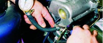
The vacuum ignition timing regulator is checked after connecting the vacuum pump and vacuum gauge to the fitting. The characteristics of the vacuum regulator are changed using adjusting washers installed under its plug.
When testing the electrical strength of the cover and distributor rotor, high voltage from the induction coil of the stand is applied to the central socket of the cover, and the high voltage output wires are connected to the spark gaps, maintaining a spark gap of 10 mm. Set the distributor shaft rotation speed to 500-700 min-1 and observe the new formation on the spark gap. The rotor and cover are considered to be in good condition if sparking at the spark gap is uninterrupted.
Connecting a motor tester to take high voltage oscillograms
The sequence of connecting measuring sensors to different types of systems differs significantly, so we will consider three types of systems that can be found on modern gasoline engines.
These are the systems:
- classic with mechanical distributor;
- DIS type system;
- SOP type system.
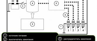
The connection to a classic system with a mechanical high voltage distributor is shown in the figure:
The synchronizing sensor of the first cylinder is installed on the high-voltage wire of the first cylinder, the measuring sensor is installed on the central wire between the ignition coil and the distributor. This connection ensures that high voltage pulses are displayed simultaneously for all four cylinders, and synchronization is carried out according to the pulse of the first cylinder.
The question arises: is it possible to connect a measuring sensor directly to the wire of the cylinder we are interested in and take an oscillogram from it?
Yes, you can, but you need to understand that due to the additional spark gap between the slider and the distributor cap, after the spark dies out, the measuring sensor is actually disconnected from the ignition coil. This phenomenon leads to the disappearance of damped oscillations on the oscillogram, which characterize the serviceability of the coil.
The ignition systems used on some Japanese and American-made cars stand out. In the literature their name is Integrated Ignition Assembly (IIA), which can be translated as “integrated ignition assembly”. Such systems are similar to classic ones, but contain a coil built into the mechanical distributor and, accordingly, do not have a central high-voltage wire.
Connecting the motor tester to a type IIA system is carried out similarly to the classic one, with the installation of the first cylinder sensor on the corresponding wire. The difference is that to take an oscillogram you need to bring the measuring sensor to the high-voltage terminal of the ignition coil, clearly visible on the cover. As practice shows, this is quite enough to obtain a stable oscillogram of the voltage on the coil with characteristic damped oscillations after the spark dies out.
Let's consider connecting the motor tester sensors to a DIS type system. It is distinguished by the use of ignition coils with two high-voltage terminals. In most cases, the coils are combined into one unit, and high voltage is supplied to the spark plugs directly from the coils through wires.
In such an ignition system, sparking occurs simultaneously in two cylinders, while the polarity of the pulses on the spark plugs of a pair of cylinders is opposite. Considering all of the above, it is not difficult to come to the conclusion: when working with the DIS system, the measuring sensors of the motor tester are installed on each high-voltage wire, and polarity must be observed. As in the case of the classical system, a synchronizing sensor is installed on the wire of the first cylinder.
Measuring sensors of different polarities are usually marked with different colors. The procedure for determining the polarity itself depends on the design of the motor tester and is described in the manual for the specific device.
To diagnose the DIS system using primary voltage, it is necessary to take voltage oscillograms on the primary windings of the coils by connecting motor tester probes to their terminals in voltage measurement mode up to 500V. In this case, synchronization can be used both from the sensor of the first cylinder, and any other, for example, by DPKV. It should be noted that a power stage for controlling the primary winding can be built into the coil body. In this case, diagnosis using the primary voltage becomes impossible.
Taking an oscillogram in the case of COP-type systems has its own characteristics. This system is characterized by the fact that each spark plug is served by its own (individual) ignition coil. Depending on the design, individual coils can be divided into two types - compact and rod.
In addition, there are designs where individual coils are combined into a module of two, three or four:
Since each engine spark plug is serviced by its own coil and commutator, we can say that each cylinder has its own ignition system. Therefore, diagnostics of COP ignition systems comes down to a sequential check of each part.
To carry out diagnostics using the primary voltage, you need to take its oscillogram by connecting one of the channels in the mode of changing the voltage up to 500V to the control terminal of the primary winding.
If an individual coil contains a built-in switch, then the control terminal is located inside the coil body and is inaccessible for connecting motor tester probes to it. This makes it impossible to carry out diagnostics using the primary voltage and it is carried out using the secondary voltage using overhead COP sensors of capacitive or inductive types of various designs.
The use of a capacitive sensor is preferable, since the oscillogram obtained with its help more accurately replicates the voltage shape in the secondary circuit of the ignition system being diagnosed. The time parameters of the oscillogram (duration of energy accumulation, moment of high-voltage breakdown, spark burning time) obtained using a capacitive sensor exactly correspond to reality.
But the amplitude values of the breakdown and combustion voltages cannot be estimated: they strongly depend on the distance between the sensitive surface of the sensor and the secondary winding of the coil - the smaller this distance, the greater the amplitude of the signal. Unfortunately, the use of such a sensor becomes impossible if the electric field created by the secondary winding is structurally shielded.
In such a situation, an inductive type sensor is used. Most often, it is required when working with individual rod-type coils or modules of several individual coils. When installing the sensor, you should select its position relative to the core of the ignition coil under study, at which the maximum amplitude of the oscillogram will be observed.
As in the case of using a capacitive sensor, correct analysis of only the time parameters of the oscillogram is possible. Amplitude values, again, cannot be estimated: they strongly depend on the relative position of the sensor and coil, as well as on the features of their design.
It should be noted that obtaining an oscillogram using clamp-on COP sensors of both types in some cases is quite a creative activity. The wide variety of designs of individual coils from different manufacturers makes it necessary to look for methods for taking oscillograms using first sensors of one type, then another, searching for a successful relative position of the coil and sensor.
One way or another, in most cases it is possible to obtain an oscillogram more or less suitable for analysis. Certain parts of it, such as energy storage, may be highly distorted due to the design features of the coil. In this case, it makes sense to conduct a comparative analysis of the oscillograms of the coils of different cylinders. As a rule, serviceable coils have waveforms of the same or very similar shape. If the voltage waveform of one of the coils is noticeably different from the others, we can talk about the presence of a defect and carry out a more detailed check.
Brief summary
To work with ignition systems, two types of sensors are used: capacitive and inductive. Classic system with a mechanical distributor: a synchronizing sensor is installed on the wire of the first cylinder, a measuring sensor is installed on the central wire. DIS type system: a synchronizing sensor is installed on the wire of the first cylinder, measuring sensors are installed on the wires of all cylinders, observing polarity. COP type system: a patch-on capacitive or inductive sensor is used, oscillogram analysis is possible by comparison, amplitude values cannot be assessed.
Purpose, principle of operation of the ignition coil
Car electrical equipment repair
The device is the most conservative part in a gasoline internal combustion engine. Its prototype was invented in Germany by the engineer Ruhmkorff in the mid-nineteenth century. It replaced magnetos in automobile engines in the early 20th century.
The main purpose of the device is to convert low-voltage electrical pulses with an amplitude of about 12 Volts (vehicle on-board voltage) into high-voltage pulses with an amplitude of more than 15,000 Volts. High voltage is necessary to break down the working area of the spark plug.
According to the type of design and ignition circuit, the coils are classified:
- single;
- double (triple, four-block);
- individual.
Ignition coil design
Single devices are used in systems with an ignition distributor. Twins are used in four-cylinder internal combustion engines without a distributor. One part forms a high-voltage pulse to the 1st and 4th cylinders, the second serves the 2nd and 3rd. Triple and quad coils are sometimes used in six-cylinder and eight-cylinder engines, respectively. Individual coils are widely used in modern cars. They are installed on each spark plug individually. A custom spark plug coil has a number of advantages over conventional ones:
- failure of one of the devices does not lead to a complete stop of the engine;
- it is easier to organize an electronic control scheme;
- the absence of a mechanical ignition distributor makes the system more reliable;
- distribution of pulse load reduces currents and increases service life;
- it is easier to identify a faulty device, which is easily done by computer diagnostics;
- Most individual coils have a pulse amplifier installed; it is controlled by low signal currents, which reduces electrical interference and increases the reliability of electrical equipment.
By type of control they are divided into:
- contact;
- electronic;
- with built-in switch (pulse amplifier).
In the ignition contact bobbins, a low-voltage pulse is generated by a chopper. When the primary circuit is switched by a breaker, an electromotive force pulse is induced in the primary circuit. The device is an autotransformer that increases the pulse amplitude N times, where N is the transformation coefficient equal to the ratio of the number of turns in the secondary to the primary winding. The transformation ratio of contact devices exceeds 1000.
Contactless systems use electronic coils. Their transformation ratio is higher and they form a stable spark. During repairs, contact and non-contact devices cannot be interchanged.
A built-in switch is installed on most individual coils, often installed on dual coils. Their disadvantage is a higher probability of failure due to the presence of electronic components.
Obtaining oscillograms of the ignition system
This is perhaps one of the most important aspects of using a motor tester.
The ignition system of a gasoline engine plays an important role in ensuring the normal functioning of the work process, and the slightest malfunction in it leads to interruptions in engine operation, a drop in power and environmental performance. Therefore, monitoring the functioning of the ignition system occupies one of the first places in the list of diagnostic procedures. Analysis of oscillograms of the ignition system and the manifestation of characteristic defects on oscillograms are discussed in the section devoted to these systems. The issues of connecting a motor tester and methods for obtaining oscillograms will also be covered here.
To record high voltage oscillograms, special sensors included in the motor tester kit are used. They can be of two types, differing in the operating principle and, accordingly, design: capacitive and inductive.
An inductive sensor is most often used to synchronize a motor tester with a high-voltage pulse from the first cylinder, although it can also be used as a sensor for taking an oscillogram in COP-type ignition systems.
The operating principle of such a sensor is similar to the operation of a transformer. Two ferrite half-rings are used as the magnetic core of such a “transformer”; the secondary winding is a coil wound on one of the half-rings, and the primary winding is the current-carrying core of a high-voltage wire.
Thus, any changes in current in the wire are converted into voltage on the winding, which is the output signal of the sensor. The formation of voltage at the sensor output is due to the phenomenon of electromagnetic induction when the magnetic field changes.
The capacitive sensor is structurally composed of insulated metal plates that form a capacitor with the current-carrying conductor of a high-voltage wire. The signal is collected due to capacitive coupling between the sensor plates and the core wire. It is these sensors that are used in most devices as meters when working with ignition systems with high-voltage wires - classic and DIS type systems. To record oscillograms of the COP system, capacitive sensors of a different design are used.
Their main difference is that the signal is collected due to the capacitance between the shielded insulated plates of the sensor and the secondary winding of the coil. There are a large number of designs of such sensors, depending on the design of the ignition system coil and the method of its installation on the engine. One way or another, the operation of all sensors of this type is based on a change in the electric field, in contrast to inductive sensors that use a magnetic field.
Both types of sensors - capacitive and inductive - are used as signal ones when taking oscillograms in the COP system. You need to understand that the oscillograms obtained with their help can have very different appearances. This is due to the different operating principles of the sensors. It is even possible that a sensor of one type is completely unable to create any real oscillogram, while a sensor of another type will display a completely plausible oscillogram. Let us repeat, we are talking about the SOP system.
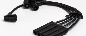
What to pay attention to
First, check the wires for visible damage - melting and insulation damage. Rapid failure of wires can be observed in the following situations: Vibration. The cause of wire failure may be engine vibration, which leads to loosening of the electrical contacts of the spark plugs. At the same time, the voltage supplied to the spark plugs increases. An increase in voltage can damage not only high-voltage wires, but also ignition coils.
High temperatures. Heat from the engine can melt insulation and wire lugs. A damaged tip disrupts the fixation of the wire and affects the operation of the corresponding spark plug. Damage to the insulation can lead to grounding of the wire to metal parts of the body, and there will be no sparking in the cylinder.
Abrasive impact. When high-voltage wires begin to touch engine parts (especially those with sharp edges), damage and breakage of the wires occurs. If this happens, there is a risk of the wire being grounded to the body.
Ignition switch malfunctions
In non-contact ignition systems with a distributor, a switch is installed; it is designed to ensure uninterrupted sparking at the spark plugs, and also serves to form a stable spark at all engine speeds, including idle. If the switched device fails, the engine begins to start poorly, and in many cases does not start at all.
The main sign of a faulty switch is that it is very hot; overheating can be determined by touching the body of the device with your hand. As a rule, along with the commutator, the coil also gets very hot. Often these parts heat up and fail on old Gazelle and Volga GAZ 31029-3110 cars with a ZMZ 402 engine. The reason for such frequent breakdowns is the low quality of spare parts supplied by various manufacturers.
Related articles:
- Repairing internal combustion engines (ICE) with your own hands Most often, major repairs of internal combustion engines are carried out in specialized car services, but it is not so rare that car owners repair engines with their own hands - much depends on the complexity of the power […]
- The benefits and harms of chip tuning The main task of tuning a car engine is to improve its technical characteristics: increasing power, increasing torque, improving dynamic and […]
- What are the most reliable engines in the world? This article will consider both the most reliable engines in the world, which do not break down for a long time, have a very good service life in terms of mileage and hours worked, and not the best power […]
Checking the resistance of the wires that lead to car spark plugs
Equipment Required: Digital Multimeter
Set the digital multimeter to measure resistance (Ohms, ?). Hold the tester's pins on both ends of the wire and determine its resistance. The Society of Automotive Engineers (SAE) has set the upper limit of the resistance value at 3,600 ohm-m. However, car manufacturers may recommend different values, so it is best to consult your vehicle's repair manual for reference.