Description of KamAZ cylinders
The sequential alternation of strokes in the engine chambers represents the order of operation of the KamAZ 740 cylinders and other modifications. When calculating this indicator, attention is paid to the characteristics inherent in the block, as well as the design features of the part that converts the force from the connecting rods into torque and the part that controls the opening and closing of the intake and exhaust valves.
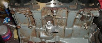
KamAZ block:
Thus, the KamAZ power unit has a V-shaped block layout. A design feature of the frame, a shift of the left row of pistons relative to the right by 29.5 millimeters. This arrangement is due to the fastening of two connecting rods on one neck, the action of the parts is directed in opposite directions. Thus, the order of operation of KamAZ cylinders follows the scheme 1x5x4x2x6x3x7x8.
The design of the crankshaft simplifies the product technologically, and at the same time increases the efficiency of the power plant. The shaft is shortened, designed for eight pistons, which are attached to cranks mounted on 4 journals. The coherence of the gas distribution mechanism, valves and cranks increases the potential of the engine.
Chapter 5.2 Engine composition, structure and operation of KamAZ-740
5.2 ENGINE COMPOSITION, DEVICE AND OPERATION
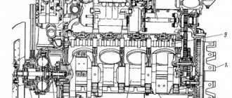
The cylinder block is the main body part of the engine and is a cast iron SCh25 GOST 1412-85.
The casting is subjected to artificial aging to relieve thermal stress, which allows the block to maintain the correct geometric shapes and dimensions during operation.
Two rows of cylinder seats, cast integrally with the upper part of the crankcase, are located at an angle of 90° to one another.
The left row of cylinders is shifted forward relative to the right by 29.5 mm, which is due to the installation of two connecting rods side by side on each crankpin of the crankshaft.
Each row has four cylinder sockets that extend onto the top machined planes, which serve as mating surfaces for the cylinder heads. The mating surfaces are characterized by high flatness and parallelism to the axis of the bores for the crankshaft bearings.
Each cylinder socket has two coaxial cylindrical holes made in the upper and lower chords of the block, along which the cylinder liner is centered, and recesses in the upper zone, forming annular areas for the collars of the sleeves. To ensure correct fit of the sleeve in the socket, the parameters of flatness and perpendicularity of the support area under the sleeve collar to the common axis of the centering bores must be performed with high accuracy.
On the lower belt there are two grooves for sealing rings, which prevent coolant from entering the engine oil sump cavity from the cooling cavity of the block.
Four bosses for fastening the cylinder head with bolts are evenly molded to the transverse walls of the block, forming the cooling jacket for each cylinder.
The main bearing caps are connected to the crankcase part of the block with main and tie bolts.
The cover of the fifth main support is centered in the longitudinal direction along two vertical pins, ensuring accurate alignment of the bores for the crankshaft thrust half-rings on the block and on the covers.
The procedure for tightening the bolts securing the main support covers is given in Appendix 8.
Boring of the cylinder block for the main bearing shells is done as an assembly with the caps, so the main bearing caps are not interchangeable and are installed in a strictly defined position. Each cover is marked with a serial number of the support; the numbering of the supports starts from the front end of the block.
Parallel to the axis of the bores for the crankshaft bearings, bores are made into which camshaft bushings of increased dimensions are pressed and bored in comparison with the serial camshaft bushings.
Valve pusher guides are cast into the crankcase camber part of the cylinder block.
Note: During the transitional period of mastering production, a cylinder block with screwed-in pushrod guides, with oversized camshaft bushings, without enlarged oil channels, with tightening torques for the main bearing cap bolts can be used in the engine:
— preliminary tightening - 95-120 N m (9.6-12 kgf m);
— final tightening - 206-230 N m (21-23.5 kgf m);
— the coupling bolts are tightened to a torque of 81-91 N m (8.2-9.2 kgf m)
Closer to the rear end, between the fourth and eighth cylinders, there is a cooling cavity bypass pipe to improve coolant circulation. At the same time, it gives the block additional rigidity.
In order to increase the circulating oil supply, an oil pump of increased capacity is installed on the engine. Therefore, the diameters of the oil channels in the cylinder block are significantly increased.
In the lower part of the cylinders, along with the block, bosses are cast for the piston cooling nozzles.
In order to install a filter with a heat exchanger on the right side, the platform was enlarged and two additional mounting holes were made, as well as a drain hole from the filter.
The cylinder liners (Fig. Installing the liner and piston cooling nozzle) are of the “wet” type, easily removable. On the conical surface in the lower part, the cylinder liners are marked as follows: installed on engines 740.11-240 and 740.14-300 - 7406.1002021, on engine 740.13-260 - 740.13-1002021.
Installing the liner and piston cooling nozzle
The cylinder liner 7406.1002021 is made of gray special cast iron, strengthened by volumetric hardening; it differs in a reduced (in height) zone of the shoulder release from the heat treatment of liners marked 740.1002021-20. Sleeve 740.13-1002021 is made of special, alloyed gray cast iron and is not heat treated.
Installing liners on engines with markings that do not comply with recommendations leads to accelerated wear of liners and piston rings. The shell mirror is a sparse network of depressions and areas at an angle to the axis of the shell. When the engine operates, the oil is retained in the depressions, which improves the running-in of the cylinder-piston group parts.
In the connection between the liner and the cylinder block, the cooling cavity is sealed with rubber O-rings. In the upper part there is a ring installed in the bore of the liner, in the lower part there are two rings in the bores of the cylinder block.
The drive of the units (Fig. Installation diagram of the gears of the drive of the units) is carried out by gears with straight teeth, which serves to transmit torque to the shafts of the gas distribution mechanism, high-pressure fuel pump, compressor and power steering pump of the car.
Installation diagram of gears npu water units
a) - for engines with fuel injection pumps equipped with a fuel injection advance clutch
b) - for engines with fuel injection pump without fuel injection advance clutch
The timing mechanism is driven by a drive gear mounted on the crankshaft through a block of intermediate gears that rotate on a double tapered roller bearing located on an axis mounted at the rear end of the cylinder block. The gear is pressed onto the end of the camshaft, and the angular position relative to the shaft cams is determined by a key.
The injection pump drive gear is installed on an oversized injection pump drive shaft. Therefore, the fuel injection pump drive shaft of engines of models 740.10 and 7403.10 is not interchangeable with the drive shaft of engines of models 740.11; 740.13 and 740.14.
The gears are installed on the engine in a strictly defined position according to the marks “E”, “0” and the marks stamped on the gears, as shown in Fig. Installation diagram of gear drive units.
The fuel injection pump is driven by a gear meshed with the camshaft gear. Rotation from the shaft to the injection pump is transmitted through the drive and driven coupling halves with elastic plates, which compensate for misalignment of the injection pump shafts and gears. The drive gears of the pneumatic compressor and the power steering pump are in mesh with the injection pump drive gear.
The drive of the units is covered by a flywheel housing mounted on the rear end of the cylinder block. On the right side of the crankcase there is a flywheel lock, used to set the fuel injection advance angle and regulate thermal clearances in the gas distribution mechanism. The locking handle is installed in the upper position during operation. It is moved to the lower position during adjustment work; in this case, the latch is engaged with the flywheel. In the upper part of the flywheel housing there are bores into which the pneumatic compressor and power steering pump are installed.
The flywheel housing is designed for installation of a single-cylinder pneumatic compressor. In the flywheel housing, unlike the flywheel housing operated with a two-cylinder pneumatic compressor, there is no flywheel housing insert and a side oil supply channel to the pneumatic compressor. Therefore, installing a two-cylinder pneumatic compressor on an engine is only possible with the mandatory replacement of the flywheel housing.
On the sides of the flywheel housing in the middle part there are two bosses with holes with a diameter of 21.3 mm for draining oil from the turbocharger. At the bottom left side of the crankcase there is a bore into which the starter is installed. In the middle of the crankcase there is a boring for the crankshaft seal. On the rear end there is a boring for the clutch housing.
On the left side of the flywheel housing there is a boss with a flange and a hatch for installing the power take-off from the engine. In the absence of a power take-off, the hatch is closed with a plug installed on a liquid gasket.
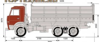
Specifications
KamAZ-740 engine - technical characteristics:
| View | Four stroke |
| Number of cylinders | 8 |
| Camber angle | 90° |
| Cylinder diameter, cm | 12 |
| Stroke of the piston part, cm | 12 |
| Engine displacement, l | 11 |
| Compression level | 17 |
| Motor power | 210 l. With. |
| Maximum torque, Nm | 650 |
| Engine weighs, kg | 750 |
| Weight of box with starter, kg | 760 |
| Number of valves | 2 on each cylinder |
| Parameters, m | 1*0,9*0,95 |
| Power supply system | injection pump |
Additional characteristics of the KamAZ-740 engine:
- Ignition occurs due to compression.
- The cooling system is liquid.
Degree position of exhaust and intake valves in different valve timing phases:
- open - 13 and 66°;
- closed - 49 and 10°.
Engine components
The design of the KamAZ 740 engine is a complex system, the functioning of which is ensured by several components at once. A well-coordinated system of the power unit and engine supply systems ensures uninterrupted operation of the power unit and the machine as a whole, and the combination of these systems makes it quite compact and allows it to provide high power.
Cooling system operation
The engine cooling system is fairly standard and not much different from most other diesel engines. The working fluid is antifreeze, and in the warm season - purified water.
A centrifugal pump supplies the coolant mixture. From there it goes to the cylinder heads: first to the left side, then to the right. Then it passes into the cylinder cavity, from where it moves under pressure to the cylinder head. After completing the full cycle, the mixture enters the thermostats. After this, depending on the position of the hydraulic pump coupling, it cools the device or drains into the radiator. Adjustment is carried out using hydraulic couplings.
Cylinder block
The cylinder block is the main working part of the engine. It is a part of the engine housing, a monolithic structure with moving parts installed in it, technological holes, and communication channels.
The block has holes for mounting the crankshaft, camshaft and piston system. During operation, the piston liners and cylinder heads form combustion chambers in which the fuel is compressed. The sleeves are made of cast iron and are electrically hardened. The material of manufacture is aluminum. The durability of the part is ensured by a cooling jacket and lubrication holes.
Design and operation of the lubrication system
The lubrication system of the KamAZ 740 engine is necessary to reduce friction of parts. Due to high operating temperatures, it performs a cooling function, reducing the operating temperature in the engine. The KamAZ 740 lubrication system is of a combined type. Oil is supplied by injection, gravity or low pressure to those parts of the power unit where it is needed most.
The lubrication system diagram is represented by devices for supplying and cooling oil, storing and filtering the mixture. From the oil pump the mixture is supplied to the filter, after which it enters the main lines. Next, oil is supplied to the cylinders, gas distribution mechanism, crankshaft, compressor and fuel pump. These parts are always subject to high friction and operate at elevated temperatures, so they require constant lubrication.
To lubricate the piston ring support, part of the oil is removed from the pistons and flows by gravity to the device, after which it flows into the pan. The hydraulic coupling is processed only if it is working: otherwise, the valve activated by the hydraulic power sensor is closed and the oil drains. From the pan, the lubricant flows into the oil receiver, and from there through the filter - again to the pump.
If there is insufficient lubricant, the engine loses power and overheats. Abscesses appear in it, which reduces the operating time of the engine. Operating an engine with insufficient lubricants is dangerous for the vehicle and the driver.
Supply system
The engine power system is a set of devices that supply fuel to the cylinder block. It consists of fuel storage tanks, fuel lines, a low pressure pump, engine injection pump and injectors. It ensures timely injection of diesel into the combustion chambers for timely fuel compression and proper engine operation.
This is interesting: SMD-18 engine technical characteristics and device
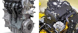
Motor specifications
| Power unit manufacturing plant | KAMAZ-Diesel; |
| The equipment was produced | 1975, present; |
| Power unit brand | 740; |
| Motor configuration and type | V-shaped, diesel; |
| Type of cylinder blocks | cast iron; |
| Installed cylinders | 8; |
| Valve installed on cylinder | 2; |
| Piston stroke support | 120-130 mm; |
| Cylinder diameter | 120 mm; |
| Volume of the power unit and compliance with the Euro standard | 10850 (Euro-0/1/2), 11760; |
| Compression amount | 16,0-17,0; |
| Power (hp/rpm) | 210/2600 – 440/1900; |
| Environmental Compliance | Euro-0-5; |
| Engine torque (Nm/rpm) | 667/1600-1800 – 2060/1250-1350; |
| Type of installed turbocharger | TKR 7N1K, TKR 700; |
| Engine weight (kg) | 750 (740.10)-885 (740.35/50/60); |
| Average fuel consumption (l/100 km) when installed on KamAZ-55111 | 36.5 l.; |
| Engine oil type | 15W-40, 5W-30; |
| Oil consumption level relative to fuel consumption | 0.8 (7403)-0.06 (740.70); |
| Oil volume in the operating engine | 28 l.; |
| Optimal oil change frequency | 16,000 km; |
| Dimensions (740.10): length | 1150 mm, width-893 mm, height-1007 mm; |
| Service life (km): according to plant regulations | 400,000/800,000/1,000,000, actual - not established. |
The engine is used in KamAZ vehicles and other Russian vehicles.
Types of motors
Despite the same operating principle, the KAMAZ 740 engine lineup has undergone significant changes. Models with more or less power for different cars were developed, reliability, maximum mileage were increased and fuel costs were reduced. Filters were added that made the actual need for maintenance more frequent and made it possible to increase the environmental standard of the motor.
Euro 0 motors marked 740.210 and 740.260
| power, kWt | 154 | 191 |
| Fuel volume, l | 10,85 | 10,85 |
| Oil volume, l. | 26 | 28 |
| Fuel compression | 17 | 16,5 |
| Weight, kg. | 750 | 780 |
| Specific fuel consumption | 155 | 207 |
Euro 2 motors marked 740 31 240 and 740 30 260
| 740.31.240 | 740.30.260 | |
| power, kWt | 176 | 191 |
| Fuel volume, l | 10,85 | 10,85 |
| Oil volume, l. | 26 | 28 |
| Fuel compression | 16 | 16,5 |
| Weight, kg. | 760 | 885 |
Euro 2 motors marked 740 51 320 and 740 50 360
| 740.51.320 | 740.50.360 | |
| power, kWt | 176 | 191 |
| Fuel volume, l | 10,85 | 10,85 |
| Oil volume, l. | 26 | 28 |
| Fuel compression | 16 | 16,5 |
| Weight, kg. | 760 | 885 |
| Specific fuel consumption | 207 | 207 |
Euro 4 motors marked 740 70 and modifications
| 740.70._____ | |
| power, kWt | 280-440 |
| Fuel volume, l | 11,76 |
| Oil volume, l. | 28-32 |
| Fuel compression | 16,8 |
| Weight, kg. | 870 |
During the improvement of the engine range, a colossal amount of work was carried out. In addition to meeting the Euro-4 environmental standard, the new engines have increased their service life several times, as well as reduced fuel consumption by 9% and reduced natural oil loss.
Internal processes
The functioning of the KamAZ installation is associated with the processes occurring in the chamber. Actions occur in a certain strict sequence with periodic repetition in each cylinder. The sum of processes is a work cycle consisting of periods of gas distribution.
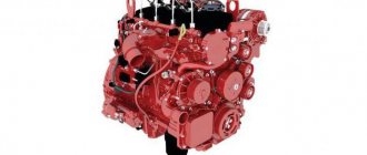
Engine KamAZ 740:
During one sequence of working processes, one ignition of fuel is performed in the cylinder. The delay period, from one flash to the next, affects the smooth running of the power unit. The smaller the gap, the less vibration when the motor operates. Smoothness also depends on how many cylinders there are in the KamAZ. In our version we are talking about eight cameras. This is a reasonable number, since a large number of cameras leads to a longer interval between flashes and harsh operation of the motor. At the same time, an insufficient number of cameras does not provide the necessary power.
The operating order of Kamaz cylinders
Dear Clients!
I, like each of us, from time to time have to buy or repair something. And, unfortunately, communication with the seller of goods or services does not always evoke positive emotions in me. Especially when you have to deal with a rude employee who stubbornly refuses to either solve your problem or call management. In such companies, a dissatisfied customer is the manager's problem. The management simply does not want to take on unnecessary worries.
I am familiar with all this, but I believe that it should not be this way. Therefore, it is very important for me to know your opinion about the work of our company: what do you like about us, and what, perhaps, makes you look for another supplier. Since I personally cannot physically track all stages of each transaction, I ask you to promptly report the occurrence of any conflict situations.
Using the feedback form, you can always write to me about your problems. If you are not satisfied with the speed of order processing, service or warehouse operation, be sure to write or call me. In turn, I promise you to take appropriate measures to ensure that such situations do not recur in the future.
Krasikov Alexey General Director
Kamaz cylinder arrangement
A correct understanding of the operating principle of the power plant depends on the numbering of the KamAZ cylinders. This procedure is approved by European regulations. According to the agreements, the manufacturer is obliged to mark the cameras of manufactured products, starting with the right front one. Knowing where the first cylinder is located on a KamAZ, it is called the main one, and the valves are adjusted.
KamAZ 740 cylinder arrangement diagram:
The nozzles that supply the mixture charge into the chamber volume are marked in pairs with the cylinder being serviced. The main sprayer is attached to the main cylinder. The KamAZ 740 is marked in the following order: right line of cameras - from the first to the fourth; left line of cameras – from the fifth to the eighth. The rows are counted from the front of the machine. This information will be useful when setting up the engine if the fuel pump is replaced. Adjusting the injection of the working mixture into the chamber without this information is impossible. In addition, the indicator affects the setting of the gas distribution mechanism.
Tools required for valve adjustment
Here, I will describe the standard method of adjusting valves on the YaMZ-238 engine. To perform this operation, you will need the following tool
:
- A 30mm wrench (preferably a socket wrench) with the ability to put a pipe amplifier on it;
- Wide slot screwdrivers;
- Socket wrench 17;
- 0.25 mm feeler gauge.
It is also desirable to have a groove for turning the crankshaft. However, if it is not available, then it is quite possible to do without it, although it will be somewhat inconvenient.
KAMAZ valve: definitions and types
Valves on KAMAZ are used in many components and mechanisms: from the engine to the brake system. These devices play a special role in the operation of the car, which is why we will dwell on them in more detail.
What is a valve?
A valve is a special device that is designed to regulate (open and close) the flow of gas, liquid, etc. The operating principle is as follows: when specified conditions occur (liquid pressure increases, flow direction changes), the valve slide changes its position and thereby increases/decreases the valve flow area.
Valve types
Depending on the functions performed, valves are of the following types: safety and control.
Safety valves are designed to protect devices and pipelines from mechanical damage that can be caused by high pressure. The operating principle is as follows: if the pressure of the working fluid or gas is normal, then the valve is in a closed state; if it exceeds the established standards, the valve is activated and relieves excess pressure.
The control valve, as its name implies, directs the flow of working fluid (gas) into one or another circuit. Thus, it provides the amount of gas (liquid) that is necessary for optimal operation of the mechanism. Operating principle: when specified conditions occur, a valve is activated, which redirects excess gas (liquid) through another circuit.
Engine valve for KAMAZ
The engine valve on a KAMAZ is used to open and close the inlet and outlet channels. This is an important part of the gas distribution mechanism, so we will dwell in more detail on the design of the valves and their adjustment.
The KAMAZ valve consists of the following parts: a head (disc-shaped) and a rod. The inlet valve is made of chrome-plated steel, and the outlet valve is made of high-heat resistant steel. The valve seats, which are pressed into the cylinder head or block, are made of heat-resistant cast iron. In addition, a heat-resistant alloy is applied to the working surface of the exhaust valve head.
Adjusting valves on KAMAZ
It is necessary to adjust the valve on KAMAZ in the following cases:
- valves are knocking;
- compression in the cylinders has dropped;
- fuel consumption has increased;
- loss of engine power;
- shots from a silencer.
Experts recommend checking and, if necessary, adjusting the thermal clearance of valves on KAMAZ vehicles once a year. To carry out this procedure correctly and safely, you will need the following tools: wrenches 13 and 14, a screwdriver, a crowbar (“crowbar”), a carrying lamp and a set of probes of various thicknesses. The following algorithm of actions must be followed:
- Place the car on a flat surface or inspection hole, turn on the parking brake;
- raise the cab and let the engine cool completely, to make this happen faster, remove the valve covers;
- to avoid accidental (spontaneous) starting of the engine, set the lever located on the high-pressure fuel pump (HPF) to the “stop” position;
- check the cylinder head bolts, if necessary, tighten them;
- lift and turn the flywheel lock rod 90 degrees (if the lock is dirty, it must be washed in diesel fuel). After such manipulations, the rod should lower and rest against the flywheel;
- remove the flywheel housing hatch cover, it is secured with two bolts (to do this you will have to go under the car);
- take a crowbar (“crowbar”) and insert it into the hole in the flywheel (this is where a carrying lamp comes in handy);
- rotate the resulting lever clockwise (the lower edge moves from the tank to the battery) until the lock rod drops into the groove of the flywheel;
- after this, you will need to get out from under the car and make sure that the marks on the flange of the drive coupling half of the injection pump drive and the end of the fuel injection advance clutch housing are at the top;
- if the marks are not visible, it means that you need to turn the flywheel one additional revolution;
- if you did everything correctly, the marks will be at the top, and the valve springs of cylinders (1st and 5th) will be in a depressed state;
- After this, remove the rod from the groove and turn it 90 degrees. After this, leave the rod in the up position.
Preparing the car
The machine being manipulated is placed on a flat surface. The driver's cabin reclines and locks. The upper part of the gas distribution mechanism is dismantled and the pump is turned off.
KamAZ 43118:
Devices:
- Keys: open-end for 13, ring for 14;
- Screwdrivers;
- Steel rod;
- Set of measuring plates.
Fixing the main chamber piston at the top
- Check the fixation force of the camera heads;
- Move the flywheel stop device down;
- Remove the flywheel housing protection plate;
- Insert the steel rod into the hole in the flywheel, turn clockwise until the product stops. Position – beginning of mixture injection (cylinder one).
Flywheel retainer, KamAZ engine:
Setting gaps
- Rotate the flywheel (2 holes - 60°, each 30°);
- Adjust the spacing of the first pair of cameras (1st and 5th). Using a 14 ring wrench, loosen the nuts
- adjusting screws. Use the 0.3 plate to adjust the intake valve, and the 0.4 plate to adjust the exhaust valve.
- Fix the nut, force 33-41 Nm.
- Adjust the spacing in chambers one through eight.
Setting up KamAZ 740, 6520, 5511 valves and other modifications:
- 180 degrees – 4th, 2nd;
- 180 degrees – 6th, 3rd;
- 180 degrees – 7th, 8th.
Adjusting clearances KamAZ:
Design and operation of the lubrication system
The KamAZ 740 engine is equipped with a combined lubrication system. Depending on where the rubbing parts are located and under what conditions they operate, oil is supplied in different ways. The system can spray, supply oil under low pressure, or let it flow by gravity.
The device supplies oil under pressure to parts that are more susceptible to wear and work in especially loaded units. This unit consists of main instruments and devices in which lubricant is stored, filtration and supply devices, as well as oil cooling.
The oil passes from the pan to the oil receiver and passes through a special filter in the form of a mesh. It then goes to the oil pump. From the injection section, through a special channel, lubricant is supplied to the oil filter, and then to the lines. Next, the cylinder head and cylinder block are lubricated through the lubrication channels under pressure, and then to other components, such as the crankshaft, gas distribution mechanism, compressor and fuel pump.
In the cylinders, excess lubricant is removed using oil scraper rings, and then goes further through the piston grooves. This lubricates the piston pin support in the upper head.
From the main line, oil is supplied to the thermal power sensor. If the valve that turns on the fluid coupling is open, then the coupling is also processed. If it is in the closed position, then liquid is supplied from the centrifugal filters into the pan.
If there is not enough lubrication, then power decreases, parts also suffer increased wear, the motor overheats, bearings melt, and pistons can seize.
Reasons for adjusting valves
When should valves be adjusted? A knock in the gas distribution mechanism immediately comes to mind. It is clear that with such symptoms, first of all, the thermal gaps are checked and adjusted. It is also worth making adjustments if the first thousand kilometers have been passed after the repair or if the cylinder head has been pulled.
It is necessary to monitor the mileage of the car and the condition of the entire gas distribution mechanism. If necessary, adjust valve clearances after 10-20 thousand km and always remember that increased thermal clearances lead to increased fuel consumption.