Maintenance of the gasoline engine power system
Carburetor engines, even with the most careful adjustment, can only meet the requirements of the Euro-2 standard, so they have been replaced by injection engines with an electronic engine control system (ECM). In our country, cars with such engines began to be produced in 1996. The first domestic injection engines were the VAZ-2111 and ZMZ-406.
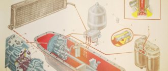
Injection engines get their name from the English word injection. Depending on the type of injection, injection engines are divided into engines with central fuel injection (mono-injection) (Figure 25) and distributed (multipoint) injection (Figure 26).
In systems with single injection, one large electromagnetic nozzle is installed in the intake manifold instead of a carburetor. It is located in front of the throttle valve. The dosing of the amount of fuel supplied by the injector is carried out by the electronic control unit (ECU) depending on the amount of air entering the intake manifold and the engine warm-up temperature. After this, passing through the intake manifold, the air-fuel mixture enters the engine cylinders. In multipoint fuel injection systems, each engine cylinder has its own individual injector. The injectors are mounted on the fuel rail and deliver fuel to the intake manifold near the intake valves. The throttle valve determines the amount of air entering the engine cylinders.
1 –engine cylinders; 2 – inlet pipeline; 3 – throttle valve; 4 – fuel supply; 5 – electrical wire through which a control signal is supplied to the nozzle; 6 – air flow; 7 – electromagnetic injector; 8 – fuel torch; 9 – flammable mixture
Figure 25 — Central fuel injection diagram
1- engine cylinders; 2 – fuel torch; 3 – electrical wire through which a control signal is sent to the injector; 5 – inlet pipeline; 6 – throttle valve; 7 — air flow; 8 – fuel rail; 9 – electromagnetic injector
Figure 26 – Multi-point fuel injection diagram
Distributed injection is the most promising and makes it possible to achieve the requirements of the environmental standard Euro-5 and higher. In turn, distributed fuel injection systems can be phased or unphased. In systems of the second type, injection can be carried out either by all nozzles simultaneously or in pairs in parallel. In phased systems, injection is carried out by each injector separately in front of the intake valve at the moment of its opening, strictly in accordance with the operating order of the engine cylinders. This improves fuel efficiency and environmental safety of the engine.
Features of the power supply system for injection engines. Unlike the power supply system of a carburetor engine, the power supply system of an injection engine has a number of differences.
- Dosage and supply of fuel is carried out by electromagnetic injectors.
- Fuel from the tank is supplied to the injectors under pressure.
- The air-fuel mixture is prepared in the intake manifold, near the intake valves.
When carrying out maintenance of a car, the power supply system of an injection engine practically does not require maintenance (except for keeping their elements clean and checking and tightening their fasteners and hose connections), and its repair consists of diagnosing and replacing failed elements that usually cannot be repaired subject to
Fuel system malfunctions. Malfunctions of the fuel system include malfunctions of the injection system, as well as malfunctions of other structural elements of the power system:
- decreased performance of the fuel pump (the pump does not create operating pressure);
- fuel filter clogged;
- clogging (deformation) of the fuel drain line, system leakage.
- The most serious malfunction is the leakage of the system, which, in addition to economic losses, poses a threat to the fire safety of the vehicle.
The main cause of these malfunctions is violation of the vehicle operating rules (use of low-quality gasoline, deviation from technology and maintenance intervals, mechanical damage, poor connection).
Fuel system malfunctions can be diagnosed by external signs. These signs are:
- interruptions in engine operation (difficulty starting, unstable idling, decreased power);
- increased fuel consumption;
- presence of the smell of gasoline inside and outside the car;
- corresponding fuel leaks (indicate a leak in the system).
It is advisable to determine injection system faults after diagnosing other elements of the fuel system. External signs and corresponding fuel system malfunctions are presented in Table 1.
Table 1 – Main faults of the fuel system
| Signs | Malfunctions |
| Difficulty starting the engine. The engine does not develop rated power | Reduced fuel pump performance |
| Interruptions in engine operation in all modes (starting, idling, driving). The engine does not develop rated power | Fuel filter clogged |
| Increased fuel consumption. The engine does not develop rated power. Difficulty starting the engine. Unstable idle | Clogged (deformed) fuel drain line |
| Increased fuel consumption. The smell of gasoline. Fuel leaks. The engine does not develop rated power. Difficulty starting the engine. Unstable idle | System leakage |
Malfunctions in the injection system occur for various reasons. The following main causes of malfunctions can be identified:
- maximum service life of the system’s structural elements;
- technical defects (defects) of structural elements;
- violation of operating rules (use of low-quality gasoline, contamination in the system, etc.);
- external influences on structural elements (oxidation of contacts, mechanical damage, moisture ingress into electronic components, etc.).
External signs of injection system malfunctions can be divided into the following groups:
- signs when starting the engine (the engine does not start; difficulty starting the engine; the engine stalls after starting);
- signs at idle (unstable engine operation at idle - unstable speed, shaking, interruptions);
- signs in the movement of the car (interruptions in engine operation during acceleration, constant speed of the crankshaft, engine braking; decreased engine power; increased fuel consumption).
The listed external signs appear when malfunctions occur in various injection system designs. These signs also accompany fuel system malfunctions and ignition system malfunctions.
External signs and corresponding malfunctions of various designs of injection systems are given in tables 2, 3, 4, 5.
Table 2 - Malfunctions of the Mono-Jetronic system
| Signs | Malfunctions |
| Cold engine does not start or is difficult to start | Pressure regulator malfunction. Malfunction of the control unit. Malfunction of the throttle position sensor. Coolant temperature sensor malfunction. Air leak in the system. Fuel system malfunctions |
| The engine starts and stalls | Throttle position sensor malfunction. Malfunction of the electric throttle servo drive. Oxygen sensor malfunction |
| The engine is idling erratically | Malfunction of the electric throttle servo drive. Coolant temperature sensor malfunction |
| A warm engine does not start or starts with difficulty | Pressure regulator malfunction. Leakage of the central injection nozzle. Control unit malfunction. Throttle position sensor malfunction. Coolant temperature sensor malfunction. Air leak in the system. · Fuel system malfunctions |
| The engine runs rough when accelerating | Leakage of the central injection nozzle. Oxygen sensor malfunction. Fuel system malfunctions |
| The engine runs intermittently at a constant speed | Throttle Position Sensor Malfunction |
| The engine does not develop rated power | Throttle position sensor malfunction. Oxygen sensor malfunction. Throttle valve malfunction. Air leak in the system. Fuel system malfunctions |
| Exhaust manifold backfires | Pressure regulator malfunction. Oxygen sensor malfunction |
| Increased fuel consumption | Coolant temperature sensor malfunction. Throttle position sensor malfunction. Oxygen sensor malfunction |
Table 3 - Malfunctions of the K-Jetronic system
| Signs | Malfunctions |
| Cold engine does not start or is difficult to start | Faulty supply pressure regulator. Malfunction of the control pressure regulator. Leaking injection nozzles. Faulty starting injector. Coolant temperature sensor malfunction. Loosening of injection nozzles. Improper throttle adjustment. Fuel system malfunction |
| The engine does not develop rated power | Malfunction of the control pressure regulator. Leaking injection nozzles. Fuel system malfunction |
| A warm engine does not start or starts with difficulty | Faulty supply pressure regulator. Malfunction of the control pressure regulator. Leaking injection nozzles. Loosening of injection nozzles. Air leak in the system. Fuel system malfunction |
| The engine is idling erratically | Faulty supply pressure regulator. Malfunction of the control pressure regulator. Leaking injection nozzles. Improper throttle adjustment. Loosening of injection nozzles. Malfunction of the additional air supply valve. Fuel system malfunction |
| The engine starts and stalls | Faulty supply pressure regulator. Malfunction of the control pressure regulator. Leaking injection nozzles. Clogged injection nozzles. Faulty starting injector. Thermal relay malfunction. Improper throttle adjustment. Loosening of injection nozzles. Malfunction of the additional air supply valve. Air leak in the system. Fuel system malfunction |
| The engine runs rough when accelerating | Faulty supply pressure regulator. Malfunction of the control pressure regulator. Leaking injection nozzles. Faulty starting injector. Malfunction of the additional air supply valve. Air leak in the system. Fuel system malfunction |
| The engine runs intermittently at a constant speed | Malfunction of the control pressure regulator. · Leakage of injection nozzles. Clogged injection nozzles. Faulty starting injector. Throttle adjustment fault |
| Exhaust manifold backfires | Malfunction of the control pressure regulator. Leaking injection nozzles. Clogged injection nozzles. Thermal relay malfunction. Improper throttle adjustment. Air leak in the system |
| Increased fuel consumption | Faulty supply pressure regulator. Leaking injection nozzles. Thermal relay malfunction. Improper throttle adjustment. Fuel system malfunction |
| Valve knocking during acceleration | Malfunction of the control pressure regulator. Leaking injection nozzles. Clogged injection nozzles. Faulty starting injector. Air leak in the system. Fuel system malfunction |
Table 4 - Malfunctions of the KE-Jetronic system
| Signs | Malfunctions |
| The engine runs intermittently when braking | Malfunction of the electro-hydraulic pressure regulator. Reference sensor malfunction |
| Cold engine does not start or is difficult to start | Pressure regulator malfunction. Malfunction of the operating pressure regulator. Coolant temperature sensor malfunction. Clogged injection nozzles. Faulty starting injector. Additional air valve malfunction. Air leak in the system. Fuel system malfunction |
| A warm engine does not start or starts with difficulty | Pressure regulator malfunction. Malfunction of the operating pressure regulator. Coolant temperature sensor malfunction. Leaking injection nozzles. Clogged injection nozzles. Fuel system malfunction |
| The engine runs rough when accelerating | Malfunction of the electro-hydraulic pressure regulator. Malfunction of the operating pressure regulator. Clogged injection nozzles. Throttle position sensor malfunction. Reference sensor malfunction. Fuel system malfunction |
| The engine is idling erratically | Malfunction of the electro-hydraulic pressure regulator. Malfunction of the operating pressure regulator. Coolant temperature sensor malfunction. Leaking injection nozzles. Faulty starting injector. Throttle position sensor malfunction. Additional air valve malfunction. Violation of idle speed control. Fuel system malfunction |
| The engine does not develop rated power | Malfunction of the electro-hydraulic pressure regulator. Malfunction of the operating pressure regulator. Throttle position sensor malfunction. Reference sensor malfunction. Violation of idle speed control. Air leak in the system. Fuel system malfunction |
| Exhaust manifold backfires | Malfunction of the electro-hydraulic pressure regulator. Working pressure regulator malfunction |
| Increased fuel consumption | Malfunction of the electro-hydraulic pressure regulator. Malfunction of the operating pressure regulator. Coolant temperature sensor malfunction. Faulty starting injector. Violation of idle speed control. Fuel system malfunction |
Table 5 - Malfunctions of the L-Jetronic system
| Signs | Malfunctions |
| Cold engine does not start or is difficult to start | Air flow meter malfunction. Malfunction of the additional air supply valve. Clogged injection nozzles. Control unit malfunction. Thermal relay malfunction. Faulty starting injector. Coolant temperature sensor malfunction. Air leak in the system. Fuel system malfunction |
| The engine runs intermittently when braking | Air flow meter malfunction. Injection nozzle clogged. Control unit malfunction. Coolant temperature sensor malfunction |
| A warm engine does not start or starts with difficulty | Air flow meter malfunction. Clogged injection nozzles. Control unit malfunction. Faulty starting injector. Coolant temperature sensor malfunction. Air leak in the system. Fuel system malfunction |
| The engine starts and stalls | Air flow meter malfunction. Malfunction of the additional air supply valve. Clogged injection nozzles. Control unit malfunction. Faulty starting injector. Air leak in the system. Fuel system malfunction |
| The engine is idling erratically | Malfunction of the additional air supply valve. clogging of injection nozzles. Thermal relay malfunction. Faulty starting injector. Coolant temperature sensor malfunction. Throttle position sensor malfunction. Air flow meter malfunction. Control unit malfunction. Air leak in the system. Fuel system malfunction |
| The engine runs rough when accelerating | Air flow meter malfunction. Injection nozzle clogged. Leaking injection nozzles. Coolant temperature sensor malfunction. Control unit malfunction. Throttle position sensor malfunction. Air leak in the system. Fuel system malfunction |
| The engine does not develop rated power | Air flow meter malfunction. Leaking injection nozzles. Control unit malfunction. Coolant temperature sensor malfunction. Air leak in the system. Fuel system malfunction |
| Increased fuel consumption | Air flow meter malfunction. Malfunction of the additional air supply valve. Leaking injection nozzles. Control unit malfunction. Thermal relay malfunction. Faulty starting injector. Coolant temperature sensor malfunction. Throttle position sensor malfunction. Fuel system malfunction |
Diagnosis of injection systems. The most reliable way to diagnose injection system faults is computer diagnostics . This type of diagnostics is based on automatic recording of deviations of system parameters from standard values (the so-called self-diagnosis mode). Identified inconsistencies are remembered and stored in the memory of the electronic control unit in the form of specific fault codes. One of the most important tasks of self-diagnosis of the engine management system is to ensure communication with diagnostic equipment. When carrying out diagnostics, special equipment (scanner or personal computer with a program and cable) is connected to the diagnostic connector, which reads fault codes. In addition to special equipment, computer diagnostics requires special knowledge and skills.
Diagnostics and repair of the electronic engine control system consists of reading fault codes stored in the controller’s memory, troubleshooting, “erasing” fault codes from the controller’s memory and then checking engine operation.
Diagnosis of injection system malfunctions can be carried out based on external signs . This type of diagnostics is used in cases where computer (technical) diagnostics are not available, as well as for preliminary diagnostics of faults.
When performing diagnostic work, it must be remembered that unprofessional intervention in the injection system can lead to damage to components and significantly complicate further repairs.
The controller informs the driver about the presence of a malfunction in the system using a diagnostic lamp . Next, the on-board diagnostic system must provide the ability to read more complete information about this malfunction stored in the controller’s memory. For this purpose, the system provides a data exchange channel with diagnostic equipment. After connecting the diagnostic tester to the system diagnostic block, an exchange takes place between the controller and the tester using a special diagnostic protocol. Diagnostic equipment (tester) is a specialized device or personal computer with a program for carrying out diagnostic work on cars with an electronic engine control system. All modern car controllers work with diagnostic equipment using a specific protocol (for example, KWP2000 - Keyword Protocol 2000). The protocol is an international standard - ISO 14230. It should be noted that the standard only defines the method of “communication” between the equipment and the controller, and the information itself (parameter tables, manufacturer-defined system fault codes, list of tested system actuators, etc.) can be different. Therefore, diagnostic equipment is not universal.
Using a diagnostic data exchange protocol, diagnostic equipment can perform the following functions necessary when diagnosing engine operation:
1. Obtaining information about the system, engine and vehicle (passport data): vehicle identification number (VIN), version and number of the controller software, date of software preparation, type of engine and control system, order number for spare parts, etc. d. This allows you to get information “without looking under the hood.”
2. Obtaining information about the values of the main parameters of the system. The controller transmits to the tester a table of values of the current system operating parameters, and the tester shows them on the display. Values are displayed in physical quantities or as graphs of changes over time. The list of parameters is determined at the system design stage and, according to the developers, is sufficient for carrying out diagnostic work in a car service center. A typical set of parameters is as follows:
coolant temperature, on-board voltage, engine crankshaft speed, throttle position, engine load (air mass), ignition timing, fuel-air mixture control parameters, idle speed control parameters, etc.
In addition to parameter values, the tester can receive from the controller voltage values of signals from system sensors (depending on the system configuration, the list of sensors will also be different). By analyzing the values of current parameters, it is possible to identify malfunctions in the system that are not detected by the self-diagnosis functions. For example, the coolant temperature value obtained by the tester is 30°C, and the temperature indicator
The instrument panel is already approaching the red zone - this indicates incorrect operation of the system temperature sensor. Or the throttle position value is 5%, and the accelerator pedal is completely released - in this case, either the throttle position sensor is faulty, or there are problems in the mechanical part of the throttle drive. In the repair manual for cars with electronic engine control systems, there are diagnostic maps that describe the sequence of actions for detecting faults using diagnostic equipment.
3. Obtaining information from the controller’s memory about malfunctions in the system . The controller error memory stores the following information:
- error code;
- status flags;
- Freeze Frame.
Error code . Each system malfunction is coded according to the international standard SAE J2012 with a five-character code. For example, P0122. The first letter "P" indicates that the error relates to the engine management system. The next character "0" indicates that this error is defined by the standard (maybe a "2"). For errors that are not included in the standard, but defined by the manufacturer, this symbol will be “1” or “3”. The following combination of characters "12" indicates the throttle position sensor. The last character shows the type of error, in our case “2” is a low signal level from the sensor.
Status flags . This is additional information about the error. They show how things are going with the malfunction at the moment: active or not, random or constant, leads to the ignition of the diagnostic lamp or not, affects the increase in toxicity or not. For different controllers there is a different set of status flags. Some controllers can report additional information to the tester: how many times the malfunction occurred, the time since the controller was reset, and up to three values of system operating parameters at the time the error was recorded.
Freeze Frame . This is a list of system parameter values fixed (frozen) at the time of the malfunction. By examining these values, you can determine when (at what temperature, crankshaft speed, load, vehicle speed, etc.) the malfunction occurred. This will help determine the cause of the error. Freeze Frame is a standard list of parameters whose values must be fixed, but control system or car manufacturers have the right to choose their own set from this list.
By command from the diagnostic tester, you can clear the controller error storage memory.
4. Running tests to check the system's actuators. When carrying out diagnostic work, there is often a need to check the functionality of the system's actuators. In this case, the tester issues a command to turn on or off (change state) the device. For example, when measuring the balance of injectors, it is necessary that there is operating pressure in the fuel system (the electric fuel pump must be turned on periodically). The fuel pump relay can be turned on using a tester without changing the electrical circuit of the system wiring harness. Diagnostic equipment allows you to check the functionality of all system relays, injectors, ignition module and canister purge valve. In addition, you can control the idle speed regulator (set the position of the regulator or the desired idle speed) and adjust the mixture composition (CO adjustment) for systems without oxygen sensor feedback.
5. Other service functions. These include resetting the controller - normal and with initial initialization of parameters. During a normal reset, the operation of the controller program goes to the initial stage (as when the power is turned on), and a reset with initialization also transfers the values of the system operation adaptation parameters (stored in non-volatile RAM) to the initial state, which is determined during the production of the controller.
The protocol makes it possible to record system and vehicle identification data into the controller’s memory. They are recorded on special equipment during car production. Many foreign companies at the end of the car assembly line not only enter identification data into the controller’s memory, but also program the controller for the desired system configuration. Thus, the diagnostic protocol is an important part in the engine management system.
Various diagnostic tools and equipment can be used to diagnose the injection system:
- diagnostic scanner (tester, scanner-tester);
- motor tester;
- automobile diagnostic stand;
- a computer diagnostic complex or a personal computer with a special computer program installed on it.
Diagnostic devices allow you to quickly detect faults using codes, identify a defective unit, and erase the code in the controller’s memory after the operator has eliminated the fault. Additionally, the program allows you to enter into the computer memory data about the owner, car, controller and the characteristics of the sensors of the car being diagnosed, and also display all this data in graphical form via a printer.
Let's look at some diagnostic tools, stands and equipment for diagnosing fuel injection systems.
Motor testers are designed for automated diagnostics of gasoline and diesel engines. The operating principle is based on microprocessor processing of signals from sensors included in the delivery kit and installed on the controlled engine. When using easily removable sensors and a strobe light, the device allows you to monitor up to 40 engine operating parameters. The measurement results are displayed on a high-resolution liquid crystal display. Other distinctive features are the presence of an interactive mode for engine testing, built-in monitoring of the health of the device, small dimensions, weight and energy consumption. Motor testers can be equipped with outputs for a printer and a personal computer. The measured parameters are stored in the device’s memory until the diagnosis is completed and the device is disconnected from the network.
The diagnostic scanner-tester is designed for diagnosing, tuning and repairing fuel injection systems (Figure 26). The scanner makes it possible to connect to the engine control unit, read and erase saved and current errors, and also check the operation of all sensors and actuators in real time. Using the tester, you can select testing modes that allow you to perform the following functions: read parameters from sensors and passport data of the electronic control unit and the vehicle; process error codes; reset error codes; control the vehicle's actuators. Depending on the type of electronic engine control unit, over 100 different parameters are recorded to monitor engine operation. The range of cars that the scanner can work with is quite wide.
Figure 26 — Diagnostic scanner-testers
Scanners provide reliable information about the technical condition of the injection system. Scanners are portable computer testers used to diagnose various electronic control systems by reading digital information from the vehicle's diagnostic connector.
The scanner kit includes the scanner itself, replaceable cartridges and connecting cables designed for connection to the diagnostic connector of the vehicle being tested. Scanners have several operating modes. In the “Errors” mode, digital codes of a particular malfunction stored in the memory of the vehicle controller are displayed on the screen. The “Parameters” mode evaluates the operation of the engine while the vehicle is moving: voltage in the on-board network, detonation, crankshaft speed, mixture composition, driving speed, etc. To view measurements of engine operating parameters in dynamics, there is a “Data Collection” mode.
Some scanners for monitoring the dynamics of the injection system and other vehicle systems can display graphical images of signals on the screen, which allows them to be observed visually. When checking a car's injection system, the capabilities of the scanners are determined by the diagnostic functions of the control unit of the vehicle; however, as a rule, all scanners read and erase fault codes, display digital parameters in real time, and control some actuators, such as injectors, solenoids, and relays. When diagnosing injection systems, simulators of signals from individual sensors (coolant temperature, throttle position, etc.) are used, transmitting signals to the control unit. Sensor signal simulators are used to simulate signals from sensors of control systems or certain impacts on the operation of the system through any inputs.
To diagnose elements of injection systems, in addition to scanners and simulators, other special devices are used to check the functioning of various input and output components of electronic control systems. Thus, a set of diagnostic equipment may include:
- a compressometer or compressograph, used to diagnose the condition of the cylinder-piston group and gas distribution mechanism;
- a universal vacuum pump (vacuum gauge), used to diagnose the condition of the CPG and valve mechanism, the presence of air leaks into the intake manifold;
- a multimeter used for diagnosing control systems and their components, measuring various parameters and signals, and making adjustments;
- strobe, used to check the correct setting of the initial ignition timing, check the characteristics of the centrifugal and vacuum ignition timing regulators or ignition timing control functions;
- a kit for measuring fuel pressure, used for diagnosing the hydraulic part of fuel supply systems of gasoline engines;
- idle air system testers, used to determine the malfunction and correct functioning of various types of idle air regulators;
- injector tester, used to diagnose the serviceability of electromagnetic injectors;
- ignition system component tester, used to determine the serviceability of coils and final modules of the ignition system;
- simulator of sensor signals, used to simulate signals from sensors of control systems, as well as to simulate various conditions and operating modes of control systems.
To clean the injectors on a running engine, autonomous devices of both closed and one-way cycles are used, supplying a special composition to the metering unit - fuel distributor in the K-Jetronic and KE-Jetronic continuous injection systems or into the fuel line in discrete-action systems ( Figure 27). At the same time, disconnect the fuel supply line and the fuel return line, turn off the fuel pump so as not to transfer dissolved deposits from the pump and fuel tank to the injectors. Such installations are designed for cleaning fuel injection systems of gasoline and diesel engines without dismantling fuel system elements, but using special cleaning liquids. Working with the settings is quite simple. The units are connected instead of the vehicle’s standard fuel system and provide cleaning fluid to the engine at a given pressure (from an external source of compressed air or from a built-in electric pump, depending on the model of the unit). After this, the car runs on the cleaning liquid in the required mode (with gas changes and breaks), which ensures cleaning.
Figure 27 – Installations for cleaning injection systems directly on the car (a) and for diagnosing and washing injectors removed from the car (b)
Basic recommendations:
- If possible, exclude starting a car engine from the ignition system of another car (the so-called “lighting”). If this happens, you should turn off the engine of the other vehicle.
- If the car’s ignition system allows another car to “light”, you should disconnect the terminals from the battery and only then connect them.
- Do not unnecessarily disconnect the ground, because in this case, information about the adaptation of the unit to the engine is erased. Maximum shutdown is no more than 1 minute. After disconnecting the “mass”, the engine must run in idle mode for at least 3-5 minutes, and then while driving, the engine should not be given full power.
- Do not use charging and starting devices to start the engine due to high voltage surges, because The ECU may fail.
- Prevent water from entering the injector, as In this case, the injectors fail.
807
Main malfunctions of the power system.
The main malfunctions of the power system are the formation of a rich or lean mixture. Due to lack of air, the rich combustible mixture does not burn completely in the engine cylinders and partially burns out in the muffler, resulting in smoky exhaust gases. The reasons for over-enrichment of the combustible mixture are:
-high fuel level in the float chamber,
- development of jet holes or damage to gaskets under them,
- clogged air jets,
- loose closing of the economizer and accelerator pump valves,
- incomplete opening of the air damper.
A lean combustible mixture also has a reduced combustion rate, the engine overheats and its operation is accompanied by sharp pops in the carburetor. The reasons for the formation of a lean mixture are a decrease in fuel supply or air leaks at the points where the carburetor and intake manifold are attached to the cylinder heads. A decrease in fuel supply is possible if the air valve in the fuel tank plug is stuck, partially clogged fuel lines, sediment filters and mesh filters, damaged diaphragm and loose fit of the fuel pump valves, loose fuel lines to the fittings, low fuel level in the carburetor float chamber, clogged fuel nozzles .
Work performed during maintenance of the power system.
During daily maintenance, check the fuel level in the tank and, if necessary, refill it with fuel; check the tightness of the power supply system by inspection.
During the first maintenance, the condition of the power system devices, the tightness of their connections are checked and, if necessary, faults are eliminated. When working in very dusty conditions, wash the bath and the filter element of the engine air filter.
During the second maintenance, check the fastening and tightness of the fuel tank, pipeline connections, carburetor and fuel pump; drive action - complete closing and opening of the air and throttle valves and, if necessary, eliminate malfunctions; use a pressure gauge to check the operation of the fuel pump without removing it from the engine; fuel level in the carburetor float chamber; ease of starting the engine. If necessary, adjust the carburetor to a low crankshaft rotation speed (idling mode), wash the filter element and replace the oil in the air filter, remove and wash the settling filter and fine fuel filter, inspect and, if necessary, clean the fuel pump sump from water and dirt.
In preparation for winter operation (seasonal maintenance), the fuel tank is washed; check the carburetor and fuel pump on special stands.
Checking and adjusting the fuel level in the float chamber.
In the K-88A carburetor installed on the ZIL-130 engine, remove the plug at the bottom of the economizer well and screw in an adapter with a rubber hose and glass tube 1 instead (Fig. 13, a). Having positioned the tube vertically, use the manual pump lever to pump fuel into the float chamber. The height of the fuel level from the plane of the connector of the upper and middle parts of the carburetor should be 18-19 mm.
If necessary, adjust the fuel level by bending the float lever or changing the number of gaskets under the carburetor needle valve body.
In the K-126B carburetor installed on 3M3-53 engines, the fuel level in the float chamber is controlled through inspection window 3 (Fig. 13.6). The fuel level should be 19-21 mm below the plane of the connector of the upper and middle parts of the carburetor.
To adjust the fuel level, bend tongue 2 on the float lever.
Checking the throughput of the jets.
The jets are checked under a water pressure of 1 m at a temperature of 20°C for 1 minute. When compressed air (pressure 1 kgf/cm2) is pumped into the lower tank 1 (Fig. 14), water flows through tube 11 into the upper tank 12. From the upper tank, water through tap 13 enters the float chamber 14. Through tube 15 through the control valve 3 water enters adapter 6 and a tube of 10 meter pressure. The nozzle being tested is inserted into tip 4 of adapter b so that water flows through it in the same direction in which fuel flows through this nozzle in the carburetor.
The working water pressure (1 m) above the nozzle being tested is set by adjusting tap 3 along a meter rod 8, moved up or down. Open taps 3 and 5. Measuring cylinder 9 is placed under running water and at the same time the stopwatch is started.
The amount of water entering the measuring cylinder in 1 minute will determine the throughput of the nozzle. For example, in the K-88A carburetor the throughput of the main fuel jet is 315 cm3/min, and the full power jet is 1150 cm3/min.
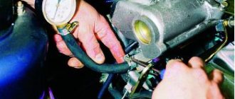
Checking the fuel pump.
To check the pressure generated by the fuel pump, attach a pressure gauge to the fuel line leading to the carburetor. When the engine is running at low crankshaft speed in idle mode, the pressure gauge readings must meet the factory requirements (excess pressure 0.2-0.3 kgf/cm2). If the pressure created by the pump is below normal, it is necessary to check the pump mounting and the serviceability of its parts.
Adjusting the carburetor to low engine speed (idling mode).
Before adjustment, check the serviceability of the engine, power system and spark plugs, the size of the gaps between the electrodes of the spark plugs and the contacts of the breaker, as well as the correct installation of the ignition. Start and warm up the engine. For adjustment, use thrust screw 1 (Fig. 15, a) in the throttle lever and screws 2 for adjusting the mixture quality. The adjustment is performed in the following sequence: tighten the stop screw approximately two turns; tighten the quality screws all the way, and then unscrew them about three turns; unscrew the thrust screw until the minimum stable rotation speed is achieved; smoothly tighten one of the quality screws until interruptions in engine operation occur, and then unscrew the screw 1/2 turn, repeat the operations with the second quality screw (Fig. 15.6).
Next, smoothly unscrew the thrust screw to reduce the crankshaft rotation speed and repeat the operations of installing two screws for adjusting the mixture quality and the thrust screw again, achieving a minimum stable rotation speed.
To check the carburetor adjustment, open the throttle valves smoothly and close them sharply. In this case, the engine should not stop.
If the engine stops, tighten the throttle lever stop screw a little and check for correct adjustment.
Share this page with your friends!
Car device
Page 1 of 14
Power system malfunctions. The main malfunctions of the power system are: stopping the supply of fuel to the carburetor, the formation of a too lean or rich combustible mixture, fuel leakage, difficult starting of a hot or cold engine, unstable engine idling, interruptions in engine operation in all modes, as well as increased fuel consumption .
Stopping the fuel supply to the carburetor can be caused by: clogged fuel lines and strainers; malfunction of the fuel pump (rupture of the fuel pump diaphragm, wear or contamination of its valves, air leakage into the cavity above the diaphragms due to loose fastening of the pump parts to each other); contamination of fine fuel filter 14 (see Fig. 32) and malfunction of double-acting valve 2. To determine the reason for the lack of fuel supply, you need to disconnect the hose supplying fuel from the pump to the carburetor, lower the end of the hose removed from the carburetor into a transparent container (so that gasoline does not hit the engine and no fire occurred) and pump up the fuel using the manual fuel pump lever or turning the crankshaft with the starter.
If at the same time a stream of fuel appears with good pressure (more precisely, the pressure created by the pump is measured using a special device), then the pump is working and you should remove the fuel filter from the carburetor inlet fitting and check whether it is clogged. If the pressure of the fuel stream is weak, or the fuel is supplied periodically with splashes or is not supplied at all, then the fuel pump is faulty or the fuel supply line from the fuel tank to the fuel pump is clogged.
It should be borne in mind that the fuel supply during manual pumping may also be absent in the case when the eccentric 1 (see Fig. 35) of the drive presses on the pusher 2, which in turn presses on the lever 18, and the rod 13 with the diaphragms is in the lowest position. position Therefore, to be sure, checking the operation of the pump using manual pumping of fuel must be repeated once or twice after cranking the crankshaft with the crank handle or starter. If during such a check there is no fuel supply and when manually pumping fuel there is no noticeable resistance to swinging the manual pump lever, then the fuel pump is most likely faulty. If, when pumping fuel, you have to apply noticeable force to the lever with the pump handle, then it is more likely that the fuel supply line from the gas tank to the pump is clogged.
Determining whether the fuel supply line from the gas tank is clogged is carried out by blowing it out with a tire pump with a special cone nozzle or using a compressor. To do this, you need to disconnect the fuel supply hose from the fuel pump, insert a cone nozzle into it and supply air into it using a pump or compressor. In this case, the air should flow into the fuel tank without difficulty (gurgling sounds will be heard in the tank). If there is poor air flow through the fuel line or its absence, you can try to blow it out by increasing the pressure of the supplied air. If it is not possible to eliminate the malfunction by purging, you should remove and clean the fuel intake pipe of the gas tank with a strainer or replace a clogged or dented fuel line from the gas tank, and also remove and thoroughly rinse the gas tank with hot water to remove any contaminants in it. If there are no blockages in the fuel supply line to the fuel pump, they proceed to troubleshooting the fuel pump.
Troubleshooting the fuel pump should begin with a thorough inspection of it in order to detect fuel leakage through leaky connections of its parts or damaged diaphragms. When fuel is drawn in through the connections of the pump parts, it is necessary to tighten their fastenings. You should also remove the pump cover, check and clean its strainer and test the pump again.
If the pump diaphragms are damaged, fuel will leak through a special hole in the lower part of the housing and also enter the engine crankcase, therefore, with this malfunction, increased fuel consumption, an increase in the oil level in the engine and a drop in its pressure due to gasoline ingress may be observed.
In this case, the diluted oil easily drains from the dipstick and smells of gasoline. These indirect signs also make it possible to identify minor damage to the fuel pump diaphragms during operation, in which the fuel pump still retains sufficient performance to ensure sufficient fuel supply for engine operation. Damaged diaphragms are replaced. If, after checking and replacing the diaphragms, the fuel supply to the pump is not restored, then it must be removed from the vehicle for repair or replacement with a new one.
Investment risk
- To the begining
- Back
- 1
- Forward
- In the end