The fundamental unit of a car is the internal combustion engine. But its functioning is impossible without the action of many other systems, including the fuel one. The power supply circuit of a carburetor engine includes a set of certain components, the functioning of which is carried out according to a certain operating principle.
The engine of any car is considered its “heart”. It is thanks to the fact that this fundamental mechanism produces torque that many electrical and mechanical processes of the car as a whole interact.
But, like any other component of the entire complex of interconnected components, the motor is not able to act separately, without affecting and involving many systems that serve it and support proper functioning (power, cooling, exhaust gases, etc.).
The term “running stock” can be applied to each car. If exaggerated, then it determines the quantitative distances that a vehicle must travel provided that the fuel tank is filled to the maximum limit, excluding the possibility of refueling.
This value, of course, is influenced by a combination of many components (weather, road surface, vehicle age, individual driving habits and much more), but the most important role is still given to the operational state of the power system and the correctness of the processes occurring in it.
Fuel System Basics
The power supply circuit of a carburetor engine is based on the following basic steps:
- fuel supply;
- its filtration and subsequent storage;
- air purification;
- preparing the fuel-air mixture;
- launching the composition into the engine cylinders
The fuel supply and circulation system directly responds to the qualitative and quantitative components of the supplied gasoline in the projection of the operating modes of the internal combustion engine.
The classic version of the fuel system includes such components as:
- fuel tank (gasoline storage);
- fuel pump (formation of the required pressure, forced supply of fuel);
- fuel line (a set of tubes, lines, hoses for circulating the fuel mixture);
- filters (air and fuel);
- carburetor (preparation and formation of fuel-air composition)
The operating principle of the power system for carburetor engines is quite simple. The fuel contained in the container is subjected to filtration at the start of its circulation. At the same time, the fuel pump comes into operation, forcing gasoline to move along the fuel line to the carburetor. There the preparation of the fuel-air composition of the required proportions begins, only after that it reaches the working cylinders of the internal combustion engine.
Next, the design and performance indicators of each element of the fuel system of a carburetor engine will be considered in more detail.
POWER SYSTEM OPERATING MODES
Depending on the goals and road conditions, the driver can use different driving modes. They also correspond to certain operating modes of the power supply system, each of which has a special quality fuel-air mixture.
- The mixture will be rich when starting a cold engine. At the same time, air consumption is minimal. In this mode, the possibility of movement is categorically excluded. Otherwise, this will lead to increased fuel consumption and wear of power unit parts.
- The composition of the mixture will be enriched when using the “idling” mode, which is used when coasting or running the engine in a warm state.
- The mixture will be leaner when driving with partial loads (for example, on a flat road at medium speed in high gear).
- The mixture composition will be enriched at full load when the vehicle is moving at high speed.
- The mixture will be rich, close to rich, when driving under conditions of sharp acceleration (for example, when overtaking).
The choice of operating conditions for the power system, therefore, must be justified by the need to move in a certain mode.
We recommend: The principle of operation of the intake manifold
Fuel tank
It is a container made of durable metal (steel) by stamping. The volume of the fuel tank varies from 40 to 80 liters of gasoline, depending on the car model; according to the standards, this amount of fuel mixture is enough for approximately 500 km. Typically, the tank is mounted at the rear of the machine.
In the internal cavity of the tank there is a partition that gives rigidity to the entire structure, and also serves as a kind of obstacle to the formation of waves when the car moves. The tank is filled with gasoline through a special neck, which is equipped with a tube. Excess air escapes through it during the refueling process.
In many car models, the gas tank design (lower part) has an additional closing hole. Through it you can not only completely drain gasoline and remove water, but also completely clean its cavity from large debris.
The gas tank is also equipped with a mesh filter, which helps in the process of cleaning the fuel mixture. The level of gasoline in the tank can be monitored using an installed sensor, which is a float with a rheostat.
The movement of the float indicates a certain level of filling of the tank with the fuel mixture. This comes down to an increase in the resistance that arises directly in the circuit and, accordingly, to a decrease in the voltage value on the indicator. The amount of fuel in the gas tank is reflected by certain indicators on the dashboard.
The design of the engine fuel system and its purpose
A car's fuel system is the system that supplies fuel to the engine. The main function of the fuel system is to supply fuel to the engine. In addition, the fuel system is responsible for storing and purifying fuel.
Let's consider the design of the engine fuel system. The elements of a car’s fuel system are a tank, fuel drives, a pump, mixture formation devices, injectors, and filters.
- Tank.
It stores gasoline or diesel. To draw fuel, the tank is equipped with a pump. - Pump.
A device that directly supplies fuel to the carburetor or injectors (depending on what type of engine is installed on the car - carburetor or with fuel injection). - Fuel lines.
Hoses, tubes with which the high-pressure fuel pump is connected to the injectors. Directly involved in transporting fuel to the mixture formation device. Fuel lines play two functions: they supply fuel to the tank, and, on the contrary, remove excess fuel. In this regard, fuel lines are supply and drain. - Mixture formation devices (injector, carburetor or single injection)
. In these devices, fuel is combined with air, resulting in an emulsion (in this form the fuel enters the engine cylinders). - Fuel level sensors.
Serve to determine the fuel level in the tank. They work in tandem with the fuel mixture level indicator on the dashboard. Sensors can be contact or non-contact. When working with traditional fuels (gasoline, diesel), contact sensors are sufficient. Non-contact sensors are recommended for aggressive environments (if biodiesel, methanol, ethanol is used as fuel). - Injection devices.
Electronics for coordination and control of the operation of injectors, sensors, misfire valves. - Filters.
Additional filters for coarse and fine cleaning. In most cases (with the exception of engines with direct fuel injection), filters are built into the pressure reducing valve (responsible for regulating the operating pressure in the system). - Fuel heaters.
Relevant for diesel engines. The need to install heaters in this case is determined by the properties of the diesel fuel itself. As the temperature drops, its viscosity level increases, which adversely affects the functioning of the device.
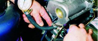
Pump
It ensures the supply of gasoline for injection and maintains the required level of pressure for the correct operation of the fuel line as a whole. The fuel pump of a carburetor engine is mounted directly into the gas tank structure and is equipped with an electric drive. In some car models, you can install a booster pump as an additional reinforcing element.
How does a car's fuel system work?
As you know, gasoline and diesel burn inside the engine cylinder chamber. The fuel system is designed to introduce a precisely measured amount of fuel into the engine cylinder in a timely manner.
If we consider the design of the fuel system of a gasoline engine, then one of the following processes occurs:
- The vehicle adds a measured portion of fuel to the air entering the engine cylinder.
- The vehicle injects a measured portion of fuel into the air in the cylinder.
If diesel, rather than gasoline, is used, then a measured portion of it enters directly into the combustion chamber of the engine cylinder, made in the piston of the diesel engine.
Dosing can be carried out using a fuel injection pump (high pressure fuel pump) or an injector - a controlled nozzle. The second option is typical, for example, for the Common Rail solution - developed by Bosch. In this case we are dealing with a high pressure circuit. With it, it is successfully possible to optimize fuel consumption (to achieve a reduction in consumption), as well as to minimize the level of toxicity of exhaust gases. In addition, the range of regulation of pressure and injection start point is expanded. This is possible by separating the injection processes and creating pressure.
Filters
The fuel filter is designed to initially clean the fuel from foreign contaminants in order to avoid unwanted breakdowns and incorrect operation of each element of the system. Recently, the fuel filter is increasingly equipped with a special pressure reducing valve. It is responsible for monitoring and regulating operating pressure.
The resulting excess fuel is removed from the valve via a fuel drain line. If the engine design has fuel injection, then the installation of a pressure reducing valve is not provided.
Complex filtration of the fuel mixture is carried out by initial (coarse) and subsequent (fine) filters. Initially, gasoline is purified by a filter - a sedimentation tank; it allows you to separate bulk mixtures of a mechanical type, as well as water. The design of such filters involves the presence of a housing, a filtration element and a settling tank itself.
The filter element is assembled from several thin metal plates with perforations and protrusions. These assembled plates are mounted on a rod and pressed against the body by means of springs. The fuel mixture is passed through the mounting gaps formed between adjacent plates. But large-volume impurities and contaminants remain at the bottom of the sump itself. They can be removed through a hole with a plug.
In the process of purifying fuel from small impurities, a fine filter is used. Its design is similar to the previous filter. Includes housing, mesh or ceramic filter element and settling tank. The entire structure is secured using a nut-bolt pair.
The air filter is responsible for cleaning dust from the air that directly enters the carburetor. This is necessary in order to reduce the degree of attraction of the smallest quartz crystals by lubricated parts, and therefore prevent early wear of components and mechanisms.
According to the principle of operation, air filters are divided into inertia-oil and dry types. The device of the former includes: a housing with a special bath, a synthetic filtration element and an air intake. If the car engine is started, then the air passing through the annular slot of the inner housing part begins to come into contact with the oil surface and changes the trajectory of its movement.
As a result, large dust particles from such a sharp change in direction cling to the oil surface. Then the initially purified portion of air reaches the filtration element, which performs a more thorough cleaning of the smallest dust particles. If heavily soiled, the filter must be thoroughly washed.
A dry air filter consists of a housing, an air intake and a filtration element made of cardboard with a porous structure. This makes it easy to replace if the need arises.
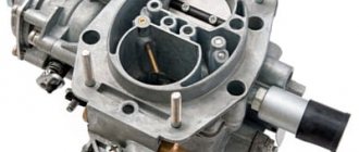
Carburetor
It is a device used to prepare the fuel-air mixture of the proper composition. The air is mixed in the carburetor with liquid fuel, for example, gasoline in the required proportions, and then supplied to the cylinders of the internal combustion engine. This mixing is the fundamental operating principle of the carburetor.
Today there are many design options for this device. But the float carburetor remains the most popular. It works according to the following principle.
Gasoline pumped by the gasoline pump enters the carburetor float chamber, in which the required fuel level is maintained using a special float and needle valve. When gasoline consumption increases, the float changes its position, at the same time the valve opens slightly, and a new portion of fuel enters the float chamber.
After gasoline is filled to the required level, the float floats up, the valve closes, and the supply of fuel liquid through the inlet hole stops. If we exaggerate, the action of the carburetor float chamber is as similar as possible to the principle of operation of the toilet flush cistern.
Through the spray tube, fuel from the float chamber penetrates into the mixing chamber, where it is mixed with the purified portion of air received from the air filter.
Direct mixing occurs as follows. When the piston first moves from top to bottom dead center, the valve is in the open position. When the piston moves down, another portion of air is sucked in and passed through the filter.
Then, with the help of a diffuser, the air movement increases significantly, it “twists”, which allows you to “catch” gasoline from the atomizer and actively mix with it. With the subsequent movement of the piston, this mixture penetrates through the open intake valve to the cylinders. All this happens in the mixing chamber, which in the language of car mechanics is called the “kitchen” of the carburetor.
The amount of fuel supplied to the cylinders is regulated by the installed throttle valve, which is mechanically connected to the gas pedal. When the driver presses the pedal, the damper opens, the content of the fuel-air mixture entering the cylinders increases, and the engine, accordingly, gains speed.
When the pedal is released, the throttle valve closes, which means the mixture content is significantly reduced. In this case, the engine slows down.
It is worth noting that the gasoline level in the float chamber is located below the sprayer outlet marker. This is what prevents the risk of fuel mixture leaking when the engine is not running, even if the car is tilted.
Modern carburetor designs are capable of ensuring the creation of a fuel-air mixture in the correct proportions under all operating modes of the engine, which ensures its most correct operation.
Carburetor power systems
Let us first consider carburetor power systems, which were widespread until recently. They are simpler and cheaper than injection ones, do not require highly qualified maintenance during operation, and in some cases are more reliable.
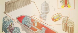
The fuel supply system for a carburetor engine includes a fuel tank 1, coarse 2 and fine 4 fuel filters, fuel pump 3, carburetor 5, intake pipe 7 and fuel lines. When the engine is running, fuel from tank 1 is supplied via pump 3 through filters 2 and 4 to the carburetor. There it is mixed in a certain proportion with air coming from the atmosphere through the air cleaner 6. The combustible mixture formed in the carburetor enters the engine cylinders through the intake manifold 7.
Fuel tanks in power plants with carburetor engines are similar to the tanks of diesel power systems. The only difference between gasoline tanks is their better sealing, which prevents gasoline from leaking even when the vehicle overturns. To communicate with the atmosphere, two valves are usually installed in the filler cap of the tank - inlet and outlet. The first of them ensures that air enters the tank as fuel is consumed, and the second, loaded with a stronger spring, is designed to communicate the tank with the atmosphere when the pressure in it is higher than atmospheric (for example, at high ambient temperatures).
Filters for carburetor engines are similar to those used in diesel power systems. Plate-slot and mesh filters are installed on trucks. For fine cleaning, cardboard and porous ceramic elements are used. In addition to special filters, individual units of the system have additional filter meshes.
The fuel priming pump is used to force gasoline from the tank into the carburetor float chamber. On carburetor engines, a diaphragm-type pump driven by a camshaft eccentric is usually used.
Depending on the operating mode of the engine, the carburetor allows you to prepare a mixture of normal composition (a = 1), as well as lean and enriched mixtures. At low and medium loads, when it is not necessary to develop maximum power, you should prepare it in the carburetor and feed a lean mixture into the cylinders. For heavy loads (their duration of action is usually short), it is necessary to prepare an enriched mixture.
Rice. Diagram of the fuel supply system for a carburetor engine: 1 - fuel tank; 2 — filter with fuel purification pipe; 3 — fuel priming pump; 4 — fine filter; 5 - carburetor; 6 — air cleaner; 7 - intake manifold
In general, the carburetor includes a main metering and starting device, idle and forced idle systems, an economizer, an accelerator pump, a balancing device and a maximum crankshaft speed limiter (for trucks). The carburetor may also contain an econostat and a height corrector.
The main metering device operates in all main engine operating modes in the presence of vacuum in the mixing chamber diffuser. The main components of the device are a mixing chamber with a diffuser, a throttle valve, a float chamber, a fuel nozzle and spray tubes.
The starting device is designed to ensure the start of a cold engine, when the rotation speed of the crankshaft cranked by the starter is low and the vacuum in the diffuser is low. In this case, for a reliable start, it is necessary to supply a highly enriched mixture to the cylinders. The most common starting device is a choke valve installed in the carburetor intake pipe.
The idle system is used to ensure engine operation without load at a low crankshaft speed.
The forced idle system allows you to save fuel while driving in engine braking mode, that is, when the driver, with the gear engaged, releases the accelerator pedal connected to the carburetor throttle valve.
The economizer is designed to automatically enrich the mixture when the engine is running at full load. In some types of carburetors, in addition to the economizer, an econostat is used to enrich the mixture. This device supplies additional fuel from the float chamber to the mixing chamber only when there is a significant vacuum in the upper part of the diffuser, which is only possible when the throttle valve is fully open.
The accelerator pump provides forced injection of additional portions of fuel into the mixing chamber when the throttle valve is sharply opened. This improves the throttle response of the engine and, accordingly, the vehicle. If there were no accelerator pump in the carburetor, then with a sharp opening of the damper, when the air flow rate increases rapidly, due to the inertia of the fuel, the mixture would at first become very lean.
The balancing device serves to ensure stable operation of the carburetor. It is a tube connecting the carburetor intake pipe to the air cavity of a sealed (not communicating with the atmosphere) float chamber.
A maximum engine speed limiter is installed on truck carburetors. The most widely used limiter is the pneumatic centrifugal type.