Preparatory and verification operations
Injection pump marking
The range of VE fuel pumps is determined by the type of diesel engines on which they are installed, and the basic data of the pump is reflected on the company plate shown for one pump as an example in the figure.
Rice. Nameplate designating the injection pump model VE
The brand of pump VE 4/9 F2250R12 is deciphered as follows:
- V—distribution type pump;
- E - denotes the fuel injection pump family;
- 4 - number of engine cylinders;
- 9 — diameter of the pump plunger, mm;
- F - indicates the type of regulator - centrifugal;
- 2250 — rated pump shaft rotation speed, min-1;
- L — left-hand rotation pump (R — right-hand rotation pump);
- 12 — performance index (for this diesel engine).
Additional digital designations on the plate are company indices, for example, 0 460 494 001 is deciphered as follows: 0 - production index, 460 - product class, 4 - indicates a VE type pump, 9 - plunger diameter index. 4 is the number of diesel cylinders, 001 is a serial number that may change during production.
In Japanese-made VE fuel pumps, the abbreviation “NP” is added to the designation, for example, VE 4/8 F 2500 LNP 347.
In addition, the nameplate may indicate the company (ZEXEL), and the same name is cast along with the pump housing.
The performer index in the pump designation can be specified depending on the configuration, so for the VW “AAZ” diesel we have:
- Bosch VE 4/9 F2300 R 432 - car without air conditioning;
- Bosch VE 4/9 F2300 R 432-4 - with air conditioning.
General verification methods
Despite the wide range of VE pumps and some design differences, there are general methods for checking and adjusting the injection pumps under consideration. Below are some techniques for simple checks of fuel equipment in the event of a diesel engine malfunction.
If there are missed flashes in individual diesel cylinders, uneven operation and loss of power associated with this malfunction, then to determine the cylinder operating intermittently, the method of sequentially turning them off at the minimum idle speed can be used. To do this, unscrew the nut securing the high-pressure pipe to the injector half a turn and determine by ear or using a tachometer the presence or absence of changes in engine operation. If there is no change in operation, this cylinder is the cause of uneven operation and, therefore, a more detailed check is required (injectors, compression, etc.).
Analysis of exhaust smoke is useful in determining the causes of diesel engine malfunctions.
Rough operation and loss of power may be due to clogged fuel suction lines with dirt or air leaks. The presence of bubbles in the inlet can be determined by installing a transparent tube on the suction line.
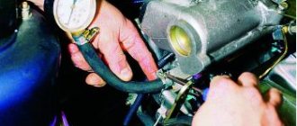
If the diesel engine does not develop maximum speed and there are signs of fuel supply problems, you should install a pressure gauge on the union of the fine fuel filter and check the low pressure value, which must correspond to the company specifications. You should also check the condition of the fuel filter and whether there is excess water in the filter separator.
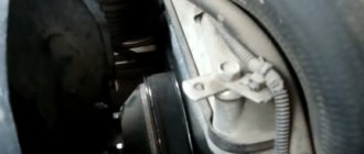
It is necessary to check the injection pump drive. to ensure that the injection timing is set correctly, especially if the engine has been repaired.
One of the first checks should be to ensure the correct connections between the governor control lever and the accelerator pedal. To do this, there must be a correspondence between the maximum idle speed and the start of operation of the regulator with the drive disconnected from the pedal, i.e. when directly acting on the control lever, and with it connected. If there is any discrepancy, adjust the drive.
An important parameter for the operation of the fuel system is the temperature of the fuel in the internal cavity of the injection pump housing, the optimal value of which should be within 45 - 50 ° C. An increase in temperature above 50°C leads to a decrease in diesel power, to a greater extent for a turbocharged engine.
Main elements and diagram of a high pressure fuel pump
The injection pump performs the task of supplying precisely measured volumes of automobile fuel into the diesel cylinders at a certain moment and under a certain pressure.
In other words, this device is responsible for the proper circulation of fuel through the fuel system.
According to the fuel supply option, high-pressure pumps are divided into units with accumulator injection and direct action. In the second case, the injection and pumping processes occur at the same moment, and the required fuel atomization pressure is provided by the movement of the plunger.
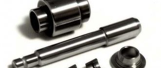
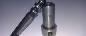
The main element of the injection pump is a plunger pair.
It is a small-diameter long piston (usually the diameter of the device is several times smaller than its length), which fits as closely as possible to the working cylinder. The gap between them (called precision mating) never exceeds 1–3 microns. The working cylinder contains inlet valves (two or one), through which fuel is supplied. It is then pushed out through the outlet valve by a plunger.
Structurally, pumps are divided into three types:
- distribution: 1 or 2 plungers are installed in it, pumping fuel and distributing it among the existing cylinders;
- in-line: has a separate plunger pair;
- main: they are responsible for pumping fuel into the battery.
Checking and adjusting basic installation modes
Fuel pump adjustments are determined by the manufacturers' instructions and must be strictly followed to ensure normal operation of the fuel equipment and, accordingly, the diesel engine.
Adjustment operations when assembling injection pumps are common for all VE pumps, differing only in specific installation dimensions, which are usually ensured by installing shims.
The table shows, as an example, the installation dimensions of the fuel pump VE 4/8 F2125 RNP286 Diesel Kiki-ZEXEL for a Mazda R2 diesel car. The numerical values of the installation dimensions given in the table must be maintained when assembling the injection pump.
Table. Example of installation dimensions
| Size name | Size size, mm |
| K | 3,20-3,40 |
| KF | 5,70-5,90 |
| L1 | 1,50-2,00 |
| L2 | 0,15-0,35 |
| MS | 1,40-1,60 |
Figures a, b show diagrams for measuring and adjusting the installation dimensions “KF” and “K” with the designation of the installation locations of the adjusting washers “A” and “B”.
Dimension "KF" is the distance between the end surface of the bushing and the end of the plunger. The “KF” size is measured using a dial indicator, which is screwed into a threaded hole in the center of the distribution head using a device.
Rice. Adjusting the position of the injection pump plunger: sizes “KF” and “K”
Dimension “K” is the distance between the end surface of the bushing and the end of the plunger when the latter is at BDC. The “K” size is also checked using a dial indicator.
The choice of the thickness of the adjusting washers should be made in accordance with the instructions of the manufacturers, which also give numerical values of the dimensions, as shown in the table example.
Figures a, b show the values of the axial clearances “L” of the regulator shaft and the centrifugal weight holder. The regulator shaft has a left-hand thread at the end for a right-hand rotation injection pump and a right-hand thread for a left-hand rotation injection pump. The gaps indicated in Figures a, b are practically the same for different VE pumps.
Rice. Adjusting the installation dimensions “L”: regulator shaft (a) and axial clearance of the weight holder (b)
Rice. Installation dimension “MS”: 1 – power lever; 2 — adjustment lever; 3—press lever; 4 - replaceable coupling tip
The installation size “MS” is important, determining the amount of starting fuel supply. The “MS” value is measured by a device with a dial indicator, which is installed instead of the regulator shaft. The measurement procedure is shown in Fig. a, b. First, the regulator coupling is pressed with your finger against the weights, after which the dial indicator is set to “zero” (Fig. a). Then the power lever of the regulator is pressed against the stop (Fig. b), after which the regulator coupling moves back until the start lever contacts the power lever. The indicator reading is the size “MS”.
Rice. Installation size of dial indicator for size measurement "MS"
If the indicator reading is outside the specified limits, you should replace the regulator coupling plug with another one, selecting the size in accordance with the spare parts specification for this pump.
Monitoring and adjustment of VE pumps
Tests and adjustments of VE fuel pumps are carried out on stands for testing diesel fuel equipment using devices, the list of which is given in the technical operation manual for the service department of the manufacturer of the injection pump or diesel engine. The table shows, as an example, the adjustment parameters of the VE diesel pump of a Mazda R2 car.
Rice. Devices for testing fuel injection pump VE: 1 - reference injector; 2 — spray body; 3—LVD tube; 4 - device for measuring the piston stroke of the injection advance machine; 5 — bracket for installing the pump on a fuel stand; 6 — fuel injection pump drive coupling on the stand; 7 and 8 - devices for disassembling and assembling the low pressure regulator
A typical set of tools used for maintenance and adjustment of VE fuel pumps by Nissan is shown in the figure. In tests on fuel stands, a process fluid for testing ISO 4113 or SAE J967d is used at a temperature of 45-50°C. As an exception, diesel fuel can be used.
The reference fuel injectors (1 and 2 in the figure) are adjusted to the injection start pressure specified in the company's instructions for this pump, and the high-pressure tubes on the stand (3 in the figure) usually have dimensions of 2.0 × 6.0 × 840 mm - internal and the outer diameters and length of the tube, respectively.
Techniques for adjusting the low fuel pressure bypass valve are shown in the figures below a, b, c, d.
Table. Adjustment parameters of the fuel pump Diesel Kiki-ZEXEL VE 4/8 F 2125 RNP 286
| Cyclic feed according to external cyclic characteristic | |||
| Injection pump shaft rotation speed, min-1 | Cyclic feed, cm3/1000 cycles | ||
| 2500 | 4.0 (maximum) | ||
| 2400 | 10,1-16,1 | ||
| 2300 | 20,1-26,1 | ||
| 2125 | 32,0-36,0 | ||
| 1500 | 37,7-39,7 | ||
| 1250 | 36,0-40,0 | ||
| 500 | 30,7-34,7 | ||
| Idle speed (minimum rotation speed) of the injection pump shaft | |||
| 350 | 6,0-10,0 | ||
| 450 | less than 4.0 | ||
| Piston stroke of the injection advance machine | |||
| n, min-1 | 1250 | 1500 | 2125 |
| stroke, mm | 3,6-4,2 | 4,6-5,8 | 8,2-9,4 |
| Pressure booster pump | |||
| n, min-1 | 500 | 1250 | 2125 |
| P, MPa | 0,27-0,33 | 0,49-0,55 | 0,73-0,79 |
| Fuel consumption for draining through a fitting with a throttle | |||
| n, min-1 | 1250 | ||
| flow rate, cm3/10 s | 49,7-93,7 | ||
Rice. Adjustments of the low pressure bypass valve: 1 - valve; 2 - spring; 3 - piston; 4 - spring ring; 5 - device; 6 — spring stop plug; 7 - device; 8 — spring ring; 9 - bypass valve
If the pressure is less than that established by the technical specifications, for example, in the table for the ZEXEL injection pump, you need to lightly hit the hammer or a rod of the appropriate diameter with a hammer to move the plug inside the valve body, thus increasing the pre-compression of the spring (Fig. a).
If the measured pressure is below the specified specifications, the following adjustment operations must be performed:
- Remove the valve from the injection pump housing and disassemble it using tool 7 in the figure.
- Using a drift, knock out plug 6 from the inside - the spring stop so that it becomes flush with the valve body (Fig. c).
- Install spring 2, piston 3 and spring ring 4 inside the valve using the tool (Fig. d).
- Make sure that the spring ring 4 is flush with the valve body after installing all its parts.
- Install the control valve into the injection pump housing.
- Adjust the pressure of the priming pump in accordance with the specifications.
Rice. Installing the device (a) and adjusting the piston stroke of the injection advance machine (b): 1 - adjusting washer
Correct adjustment of the injection advance machine is important for the normal operation of a diesel engine. For this purpose, a device is used with which the piston stroke of the machine is checked. The device is installed instead of the machine cover on the side without a spring, if the injection pump does not have an automatic KSB drive, and on the side with a spring, if there is one. Installation of the device is shown in Fig. a, measurements are carried out in the modes specified in the manufacturer’s instructions, for example, in the ZEXEL standard. and adjustment is carried out by installing/removing adjusting washers, as shown in Fig. b.
An important role in the operation of the pump is played by the throttle in the fitting at the outlet of the injection pump housing, which determines the fuel consumption for draining and, therefore, participates in the formation of fuel pressure in the internal space of the injection pump. The amount of fuel returned (to drain) is determined by the specifications of the manufacturers, in particular ZEXEL, and can be measured when testing the pump on a bench with the appropriate connection of the drain tube, as shown in the figure below.
Rice. Measuring fuel consumption per drain
Rice. Installing the control lever on the maximum mode stop (a) and adjusting the nominal fuel supply (b)
Measuring the amount of fuel consumption going to drain is carried out as follows:
- Set the control lever to the maximum speed stop using a spring or other suitable device.
- Apply 12V voltage to the fuel cut-off solenoid valve
- Measure the volumetric flow rate of the returned fuel.
If the measured flow rate does not meet the technical requirements, check the condition of the throttle, the size of its hole (usually 0.6 mm), and the possible presence of lag.
Adjustment of the cyclic feed value and adjustment of the regulator in the maximum load mode is carried out using the maximum feed screw (Fig. a, b) with the control lever pre-installed on the stop in the maximum rotation speed screw, after which both screws are sealed and allow intervention only by qualified personnel with the appropriate equipment .
The position of the control lever is determined by the size “p” (Fig. a), which depends on the brand of the VE pump; sometimes the company’s specifications indicate the angle of rotation of the lever, which for the VE injection pump of the Mazda R2 engine should be in the range of 40-60°, and for example, for The fuel injection pump of the Nissan CD-17 diesel engine has a linear dimension “p” of 11-16 mm (SDS specification). In each individual case, adjustment must be carried out in accordance with the instructions of the manufacturer of this diesel engine. So, when checking the value of the cyclic feed, you must strictly maintain the speed limit (for example, in accordance with the table) and, if necessary, adjust the maximum feed screw. When turning the adjusting screw, the feed increases, and when turning it away, it decreases. The amount of starting feed is determined by the “MS” size, and in some diesel engines it can also be set by an adjusting screw.
The procedure for performing operations to adjust the minimum idle speed and accelerated idle speed is also determined by the relevant specifications or operating instructions for specific engines.
Below are examples of idle speed adjustments on fuel injection pumps from several well-known automobile companies, which will allow the reader to imagine, in principle, the entire range of such adjustments.
Adjusting the idle speed of Volkswagen diesel engines
The adjusting screws for the injection pump VE 4/9 F 2250 Volkswagen diesels are shown in the figure. Adjustment of idle modes is carried out as follows.
The minimum idle speed of diesel engines without turbocharging, indicated in the caption, should be 900 min-1, for a diesel engine with turbocharging (AAZ) - 980 min-1.
Rice. Injection pump adjustment screws for Volkswagen engines: 1 - idle speed adjustment screw: 2 - maximum rotation speed screw; 3 - limit screw for minimum idle speed; 4 — fast idle limit screw; 5 - minimum mode stop
The rotation speed is adjusted using screw 1. If by turning screw 1 it is not possible to adjust the required rotation speed, you should loosen the lock nut of screw 3, unscrew screw 3 and use screw 1 to achieve the required rotation speed, then tighten screw 3 until it touches the minimum idle speed limit lever , tighten the lock nut of screw 3.
The fast idle speed is adjusted by screw 4 in the following order:
- Check that the minimum idle speed is adjusted correctly.
- Pull the cold start accelerator handle to the first fixed position, and the rotation speed should increase by 60 min-1.
- Pull the handle all the way out and check the fast idle speed, which should be in the range of 1000-1100 min-1.
- If the rotation speed deviates from the norm, loosen the lock nut of adjusting screw 4. Adjust the fast idle speed with this screw and tighten the lock nut.
Adjusting the maximum idle speed:
- Start and warm up the engine (oil temperature is at least 60°C).
- Quickly press the accelerator pedal all the way and check the speed, which should be in the range of 4950-5150 min-1.
- If the rotation speed deviates from the norm, adjust screw 2.
Note: Screw 2 is located under a seal and its adjustment can only be performed by a qualified mechanic or the company's service department if the diesel engine is under warranty.
The final adjustment of the minimum idle speed is carried out with screw 5. When screwing screw 5 in, the rotation speed increases, and when unscrewing, it decreases.
Note: The position of the minimum mode adjusting screw is set at the factory and should not be changed during operation.
Adjusting the idle speed of CITROEN diesel engines
The location of the CITROEN diesel injection pump adjusting screws is shown in Figures a, b.
Before making adjustments, warm up the engine and turn off all auxiliary equipment. The rotation speed for AX diesel engines should be 775 ± 25 min-1, for Saxo diesel engines - 800 ± 25 min-1, accelerated idle speed - 1000 ± 25 min-1.
Adjusting the minimum idle speed (Fig. a):
- Start and warm up the engine.
- Unscrew screw 1 until there is a gap between screw 1 and control lever 2.
- Adjust the rotation speed using the idle speed screw 3.
Rice. Adjusting screws of the fuel injection pump of the VJY/VJZ engine (TVD 5/L/Y L3 Citroen AX 1.5 D SAXO 1.5 D): a: 1 - minimum mode stop; 2 — control lever; 3 — idle speed control screw; b: 1 - clamp; 2 - nut; 3 - cable; 4 — stop lever; 5 — control lever (accelerator); 6 — screw of maximum rotation speed; 7 — accelerator cable clamp; 8 - minimum speed screw
Adjusting fast idle speed:
- The engine is cold - lever 4 (Fig. a) should be on the stop (Fig. a).
- If not, adjust the cable tension using clamp 1 (Fig. b), fine adjustment is made using knurled nut 2 (Fig. b).
- Press lever 4 against screw 5 (Fig. a) and adjust the fast idle speed with screw 5.
- On a warm engine, cable 3 (Fig. b) should be in a loose state.
Adjustment against arbitrary engine stop:
- Insert a 1 mm thick feeler gauge between control lever 2 and screw 1 (Fig. a).
- Adjust the rotation speed according to specifications.
- Remove the dipstick.
- Increase the rotation speed to 3000 min-1 by turning control lever 2 and releasing the lever.
- The speed should decrease to idle within 2-3 seconds.
Adjusting the idle speed of FIAT Scudo and Ulysse diesel engines
Figures a, b show the location of the fuel injection pump adjustment screws for FIAT Scudo and Ulysse diesel engines. The minimum idle speed is 830-880 min-1 for the Scudo diesel engine and 750-800 min-1 for the Ulysse, accelerated idle speed is 900-1000 min-1 for both engines.
Rice. Adjusting screws of the fuel injection pump of the D8B FIAT Scudo 1.9 TD engine: a: 1 - lever: 2 - idle speed adjusting screw; 3 — minimum mode stop; 4 — fast idle screw; b: 1 - stopper; 2 - splined bushing
Adjusting the minimum idle speed:
- Warm up the engine.
- Make sure that lever 1 is against screw 2.
- Adjust the minimum idle speed with screw 2 and tighten the locknut.
- Insert a 1 mm thick probe between the control lever and adjusting screw 3 - the minimum mode stop (“X” in the figure).
- The rotation speed should increase by 20-50 min-1.
- If not, adjust screw 3, then tighten the locknut.
Adjusting fast idle speed:
- Install lever 1 on the stop in adjusting screw 4.
- Adjust the fast idle speed and tighten the locknut.
Accelerator cable adjustment:
- Turn off the ignition.
- Remove spring stopper 1 (Fig. b).
- Adjust the cable tension using the splined bushing 2. ensuring easy gluing.
- Install stopper 1.
Adjusting the idle speed of RENAULT diesel engines
The figure shows the location of the adjustment screws for the injection pump of a RENAULT diesel engine. The minimum idle speed should be 775±25 min-1, accelerated speed - 875±25 min-1. The adjustment procedure is almost the same as discussed above for the Fiat diesel engine. The fuel injection pump under consideration has a damper 7 of the control lever, the adjustment of which consists of the following operations:
- Make sure that lever 4 is on stop 2.
- The length of the damper at idle should correspond to the mark on its body.
Rice. RENAULT engine fuel injection pump adjusting screws: 1 - minimum rotation speed screw; 2 — minimum mode stop; 3 — control lever; 4 — lever; 5 — fast idle screw; 6 — cable clamp; 7 - damper.
Toyota Land Cruiser 3.0D Turbo diesel idle adjustments
The adjusting screws of the DENSO VE injection pump are shown in Figures a, b, c. The minimum idle speed is 700±50 min-1, the speed with the air conditioner on is 950.
Rice. Injection pump adjustment screws for DENSO VE, TOYOTA Land Cruiser: 1 — minimum mode stop; b: 1 - gap between the control lever and the fast idle screw; 2 — fast idle screw; c: 1 - vacuum hose; 2 - adjusting screw
Adjustment procedure:
- Disconnect the accelerator linkage.
- Warm up the engine.
- Adjust the minimum idle speed with screw 1 (Fig. a).
- Connect the accelerator linkage.
- If necessary, adjust the length of the accelerator rod.
Adjusting the fast idle speed (Fig. b):
- Measure distance 1 between control lever and screw 2 (specified in Nippon DENSO specifications).
- If the specification does not meet, adjust with screw 2.
Adjusting the high idle speed when the air conditioner is running (Fig. c):
- Warm up the engine and adjust idle speed.
- Turn on the air conditioner.
- Disconnect vacuum hose 1 from the actuator.
- Apply vacuum to the servomechanism.
- Increase the rotation speed to 2500 min-1 for a few seconds and “relieve the gas”.
- Check the speed value and if it does not meet the specification (950 min-1). adjust with screw 2.
- Repeat the check.
- Connect the vacuum hose.
Setting injection advance angles for injection pumps
A very important role in the normal operation of a diesel engine is the correct setting of the fuel injection advance angle. Checking the injection advance angle in dynamics is carried out with a stroboscopic flash lamp on a stand or on the engine and, if necessary, the static injection advance angle is adjusted, followed by a dynamic check.
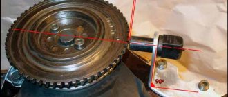
The static injection advance angle is measured by a dial indicator installed in the head of the injection pump housing instead of a threaded plug when the piston of the first cylinder is in the BMT position of the compression stroke and the corresponding alignment of the marks on the flywheel or crankshaft pulley and the injection pump installation marks on the diesel engine.
Thus, the indicator measures the stroke of the injection pump plunger from BDC of the pump to the start of fuel supply. The corresponding angle designations and plunger movement are regulated by the operating instructions for specific engines. The presented materials give an idea of the main parameters when assembling and adjusting VE fuel pumps and allow for simple adjustment work, which are, in principle, common to most high-speed diesel engines equipped with Bosch VE Diesel injection pumps Kiki-ZEXEL, NIPPON-DENSO, MICO (Bosch Group).
Some VE fuel pump models may have automatic TAS and TLA devices installed.
Diesel engines of Japanese cars are equipped with VE fuel pumps from ZEXEL (Diesel Kiki), which have some additional devices depending on the car model. In particular, if the car is equipped with air conditioning, a pneumatic device is installed on the VE injection pump to increase the idle speed. In VE ZEXEL fuel pumps there may be some other design differences from VE injection pumps from other Bosch divisions, which are not of fundamental importance.
Typical fuel injection pump problems on 4D56, 4M40 and D4BH engines
Basically, the accelerated output of the injection pump on these engines is caused by low-quality fuel, as well as the entry of foreign elements into the system, which often occurs when there are loose connections and driving over rough terrain, fords, etc.
The main problems with the injection pump on these engines are the following:
- Damage (due to accelerated wear) of the internal parts of the pump - plunger pair, bearings and other parts.
- Filter contamination (protective mesh and element) due to foreign elements entering the system.
- Increased or floating speed due to the so-called “airing” of the system is the entry of air into the system due to loose connections and worn gaskets and seals.
- Poor engine starting in cold weather, caused by a jammed or broken thermostat (located on the left side of the pump, injection advance mechanism).
- Other breakdowns related to other elements - spark plugs, automatic warm-up, fuel supply, diesel injection advance angle settings.