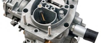
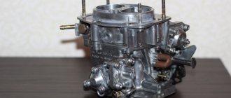
The principle of operation of a car carburetor
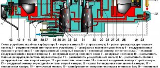
The function of the carburetor is to mix atmospheric air with fuel and then transport it into the combustion chamber. Everyone knows that oxygen is necessary for ignition and subsequent combustion, and to ensure that dust and other unnecessary particles do not penetrate into the combustion chamber with air, a special filter is used. During operation, the engine is constantly supplied with oxygen, just like with gasoline. Fuel is supplied to the carburetor by a fuel pump, which drives the crankshaft or camshaft using cams or gears. The accelerator drive, located on the carburetor and connected to the gas pedal inside the car, regulates the engine speed. The accelerator regulates the position of the carburetor throttle valve, which is responsible for the amount of fuel mixture entering the engine. Simply put, a carburetor is a mixer of gasoline and oxygen that regulates its supply to the combustion chamber of the engine.
What is the air damper for?
The carburetor air damper is located in the upper part of the carburetor and is externally a piece of round or oval iron sheet. Its main task is to limit the access of air that enters the carburetor. The method of operation of the air damper is the same as that of the throttle valve, the only difference being that its operation does not depend on the accelerator pedal.
With the help of the choke, a cold engine starts without much effort. For example, in the morning the engine is cold and during the night some gasoline turned into condensate and did not enter the combustion chamber. The remaining fuel is not enough to ignite the mixture and start the engine. In such a situation, the air damper comes to the rescue, which, when closed, reduces the flow of air into the carburetor and thereby increases the amount of fuel entering the combustion chamber. As a result, the engine starts when it is not warmed up. The choke then opens again, reducing fuel consumption and opening the oxygen supply to the carburetor.
Throttle valve
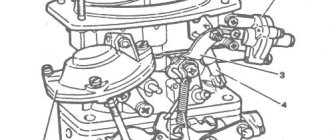
The throttle valve is a carburetor control element connected to the gas control via a flexible connection.
It regulates the flow area of the diffuser, moving perpendicular to the axis of the main air channel. In many carburetor models, the throttle valve is a cylinder that moves on a sliding fit inside the carburetor body. Even in carburetors with a constant vacuum (in the literature there is a term - with a constant flow rate), in which the throttle valve performs rotational movements, there is a valve that regulates the cross-section by moving perpendicular to the axis of the diffuser. The design and operating principle of such carburetors will be discussed later, since their features deserve a separate section.
Butterfly valves are classified according to their shape into cylindrical and flat (they are also called gate valves - the term is appropriate, since in accordance with GOST 24856-2014 “Pipeline fittings. Terms and definitions”, a gate valve is defined as “a parallel valve in which the locking element is made in plate form"). The figure below shows a comparison of the sizes of round and flat dampers. A flat throttle body creates less parasitic turbulence underneath by reducing the length of the diffuser.
General view of round and flat throttle valves. The guide holes for the dosing needles in the center of the flaps are highlighted in color.
The following figure shows the difference in the lengths of the main air passages when using a round and flat damper. It can be seen that a carburetor with a flat throttle body has a shorter channel, which means there is less resistance to air flow.
Comparison of the lengths of the main air channels with cylindrical and flat dampers
The diffusers of modern carburetors are carefully designed to reduce parasitic turbulence at the junction of the throttle valve and the carburetor body. For example, in the figure below under the letter a
shows a Dellorto carburetor of the VHSD series (For example, the designation PH in the Dellorto carburetor series stands for P (Piston) - cylindrical throttle valve, H (Horizontal) - horizontal orientation of the longitudinal axis of the main air channel. The letter V (Valve) in the names of other lines (for example VHSD ) indicates the presence of a flat throttle valve), in the diffuser of which two thin guide grooves are visible along which the throttle valve moves, like a guillotine.
And in the picture under the letter b
the VHSB series carburetor throttle valve is demonstrated, installed in a special “cup”, which serves as a guide for its movement. The damper assembly with the cup is installed in a cylindrical seat of the carburetor body.
a - guides for moving the throttle valve, b - guide cup for the throttle valve.
The throttle valve of carburetors with a metering needle, both flat and cylindrical, has a bevel, which affects mixture formation at low throttle lifts. A low-ramp choke will richen the mixture up to 1/4 throttle lift, but if the mixture is too rich, a high-ramp choke can be used. It should be borne in mind that even a small change in this adjustment parameter can significantly affect mixture formation.
Throttle valves with different bevels
Choke control
To control the air damper, both manual and automatic choke are used.
- Manual control of the carburetor air damper occurs using a cable that is stretched from the damper to the control lever inside the car. To close the damper, pull the lever towards you until it stops. As the engine warms up, the lever is gradually retracted to its original position. Once the engine starts running at a constant speed with the throttle open, you can start driving. This control method was used on earlier cars;
- Automatic control of the carburetor air damper is somewhat simpler than manual control. Here a spring is used, which takes over control of the damper drive. When the engine heats up, the spring becomes softer and automatically opens the damper, thus regulating the amount of air supplied to the carburetor.
Damage to the carburetor air damper
For the carburetor to function properly, the choke valve must operate without any malfunctions. Any jamming of the carburetor air damper leads to increased fuel consumption and difficulty starting a cold engine.
One of the reasons for the damper sticking is the incorrect operation of the return mechanism; in such a situation, it does not return to its position. In addition, the lever or damper axis may be the reason for the choke to not work properly. In this situation, you should check the correct operation of the damper in the engine compartment of the car and eliminate any detected problems.
Another failure of the damper is hidden in the damage to the cable. Often the cable breaks, as a result of which there is no reaction to changing the position of the handle. In this situation, you should replace the damaged cable with a new one. The cable could also stretch, as a result of which the damper will also not respond to the movement of the handle. To solve this problem, unscrew the bolt on the handle that clamps the cable. Then pull the cable to the required length and tighten the fastener. Then check the correct operation of the damper.
When automatically controlling the air damper, the spring most often fails. There is only one solution in this case - replacing the spring. It is also necessary to check the serviceability of the damper axis and control lever.
Classification of electric actuators of air valves
Electric drives can be divided into several main types, each of which is focused on performing specific tasks. Thus, manufacturers of electric drives today offer the following types of equipment:
By spring return
- without return spring;
- with return spring.
By management
- Two-position;
- 2- and 3-three-position;
- Modulating.
By torque
- from 2Nm to 40Nm.
By voltage
- 24V;
- 230V.
By auxiliary switches
- without additional switches;
- with additional switches.
Manufacturers focus on two main divisions of electric drives, which in all cases have fundamental differences.
Electronic damper
The last type, electronic, is being introduced into cars more and more. Its main feature is the absence of direct interaction between the accelerator pedal and the damper axis. The control mechanism in this design is already completely electric. It uses the same electric motor with a gearbox connected to the axle and controlled by the ECU. But the control unit “manages” the opening of the damper in all modes. Another sensor was additionally added to the design - the position of the accelerator pedal.
Electronic throttle elements
During operation, the control unit uses information not only from the throttle position sensors and the accelerator pedal. Signals coming from tracking devices of automatic transmissions, braking systems, climate control equipment, and cruise control are also taken into account.
All incoming information from the sensors is processed by the unit and, based on it, the optimal opening angle of the damper is established. That is, the electronic system completely controls the operation of the intake system. This made it possible to eliminate errors in mixture formation. In any mode of operation of the power plant, the exact amount of air will be supplied to the cylinders.
But this system is not without its drawbacks. Moreover, there are slightly more of them than in the other two types. The first of these is that the damper is opened by an electric motor. Any, even minor, malfunctions of the drive components lead to disruption of the unit, which affects the functioning of the engine. There is no such problem with cable control mechanisms.
The second drawback is more significant, but it mostly concerns budget cars. And it comes down to the fact that due to not very well-developed software, the throttle may work late. That is, after pressing the accelerator pedal, the ECU takes some time to collect and process information, after which it sends a signal to the electric motor of the throttle control mechanism.
The main reason for the delay from pressing the electronic gas pedal to the engine response is cheaper electronic components and unoptimized software.
Under normal conditions, this drawback is not particularly noticeable, but under certain conditions such work can lead to unpleasant consequences. For example, when starting to move on a slippery section of the road, sometimes there is a need to quickly change the engine operating mode (“play with the pedal”), that is, in such conditions a quick “response” of the engine to the driver’s actions is needed. The existing delay in throttle response can lead to complications in driving, since the driver does not “feel” the engine.
Another feature of the electronic throttle of some car models, which for many is a disadvantage, is special factory settings for the throttle operation. The ECU contains an installation that eliminates the possibility of wheel slipping at start-up. This is achieved by the fact that when starting to move, the unit does not specifically open the throttle to obtain maximum power; in fact, the ECU “strangles” the engine with the throttle. In some cases, this function has a negative effect.
On premium cars there are no problems with the “response” of the intake system due to normal software development. Also, on such cars it is often possible to set the operating mode of the power plant according to preferences. For example, in the “sport” mode, the operation of the intake system is reconfigured, and in this case the ECU no longer “strangles” the engine at the start, which allows the car to “briskly” start moving.
Spring return actuator
The equipment is designed to work in heating, air conditioning, and ventilation systems. The device primarily performs protective functions. When the air damper of the valve moves to the operating position, a spring is activated in the electric drive, which starts the action mechanism. When the current supply is stopped, the spring still returns the damper to its original position. The basic principle of operation of the return spring is that simultaneously with the rotation of the air damper to its normal position, the spring itself is activated. In the event of a power outage, the damper automatically returns to its initial (protective) position.
Actuator without return spring
This equipment is designed to work correctly with air dampers in air exchange systems. Directly in the drives of this type, the spring, when the power supply is cut off, retains its original position.
The choice of electric drive according to the type of control is of fundamental importance. Speed, convenience and efficiency - all these characteristics are of fundamental importance when it comes to choosing ventilation equipment.
- Two-position control - represents the specificity of control: turning on or off the power supply. Turning on the power supply activates the drive into operating condition. Turning off the power allows the actuator spring to freely return the choke to its standard position.
- Three-point control - with this type of control, the position of the rod does not depend in any way on the specific voltage. The actuator receives an opening or closing signal. The magnitude of the main signal is constant, but it arrives through different channels. When one contact is closed, the actuator assumes an open position (or closed); when the second contact is closed, the actuator operates exactly the opposite. If the power supply is completely absent, the drive stops. Thus, by applying a sequence of electrical pulses to the appropriate contacts, the actuator can be moved to absolutely any position.
- Analog control - with this type of control, the position of the electric drive directly depends on the magnitude of the electrical voltage in the range from 0 to 10V. So, for example, if the controller detects that a valve controlled by an electric drive should be opened halfway, then it sends a signal with a nominal value of 5 Volts. If the valve needs to be fully opened, then the control signal should be 10V. This equipment works exactly on this principle.
Having decided on the type of control, you can proceed to selecting the torque for the electric drive of the air valve. It depends on a number of factors, namely:
- The larger the total area of the air damper, the higher the drive torque must be.
- Swing-leaf valves require less torque than parallel-leaf valves.
- Equipment that is highly sealed requires more torque than dampers without enhanced sealing.
- Ventilation system pressure and specific air flow velocity additionally influence valve torque characteristics.
Important:
The position of the damper and actuator also influences the choice of torque. These factors should also be taken into account. Prefer a valve actuator with a torque rating that is greater than the required damper torque.
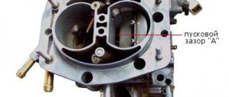
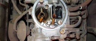
Setting the air damper of the Solex and Ozone carburetors
In order for the engine to start confidently and continue to operate normally, it is necessary to correctly adjust the carburetor air damper mover. If the damper is incorrectly adjusted, for example, it does not completely close the air supply, a cold engine may simply not start. If the air damper does not open completely, fuel consumption increases and idle speed adjustment becomes almost impossible.
To adjust the carburetor air damper, we need two 8-mm open-end wrenches.
Checking the operation of the damper:
- First, you need to unfasten the air filter cover (so that you can see the damper);
- Then close the air damper completely (there should be no gaps between the damper and the carburetor air chamber);
- Then open the damper completely. When operating correctly, it should be in a vertical position and completely open the carburetor air chamber;
- If the air damper closes or does not open completely, it needs to be adjusted.
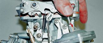
Adjusting the carburetor air damper drive:
- First you need to remove the air filter from the carburetor;
- Open the carburetor air damper, completely recessing the choke lever;
- Loosen the screw on the damper control lever (which clamps the cable);
- Loosen the screw that secures the suction cable casing;
- We check that the choke handle is completely recessed;
- Turn the damper adjustment handle all the way and, leaving 1 cm to the choke cable casing, clamp it;
- Then open the air damper completely, and in this position tighten the screw that holds the choke cable.
By pulling the choke handle several times, we make sure that it opens and closes completely. The air damper setting is complete.
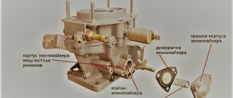
Electric carburetor choke drive
Systems of this type consist of a gear motor (which is responsible for the mechanical part of opening the air damper) and an adjustment device. The control device is programmed via a laptop or computer. Settings can also be made using a computer or manually (with buttons that are connected separately, in the amount of three). The system of automatic control of the carburetor air damper has two main functions - setting the engine speed at a certain temperature. There is also the possibility of manual control using a button located inside the car. The electric carburetor air damper drive does not have any additional functions (except for a temperature sensor and settings).
That's basically all you need to know about the carburetor choke. As it turned out, this fuel system unit turned out to be not so complicated and can easily be adjusted and repaired.
If you have any questions, leave them in the comments below the article. We or our visitors will be happy to answer them
Selecting an electric actuator for servicing the air valve and damper
An air ventilation valve is an integral component of the ventilation system, which provides regulation and control of air flows, which allows you to fully serve premises (both office and industrial) with fresh air and significantly increase the level of fire safety.
Externally, the air valve is a device with a metal body. Inside it there is a special blade, which is attached to an axis. The valve is always made individually to the dimensions of the air duct.
The intensity and speed of air flows are adjusted using a manual or automatic electric drive. Thus, choosing a suitable electric drive allows you to solve a number of important problems that are responsible for the efficiency and safety of all ventilation systems.
What should you pay attention to when choosing an electric drive?
In order to select the appropriate actuator for a particular type of valve, the user must consider a number of factors, namely:
- First you need to find out exactly how the actuator is connected to the operating valve? This is done directly or using a lever device. If the actuator is connected directly, then the dimensions of the rod and the original dimensions of the device must be taken into account.
- It is necessary to decide on the type of actuator, what will it be? Manual, electric, pneumatic.
- Functional reference. What functions is the valve purchased for?