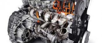
Externally, an aircraft's turboprop engine is very similar to piston-type engines. But their similarities are only visual, since in everything else they are completely different. This engine has completely different characteristics, type and mode of operation, and their capabilities also differ.
A turboprop engine is essentially a gas turbine engine, which is in great demand in the aircraft industry. The gas turbine engine was created for a single purpose, it was to become a universal energy converter, thanks to this feature it began to be used in aviation.
A gas turbine engine is a kind of heat engine. At the moment of fuel combustion, gases are released, which rotate the turbine, thereby creating torque. It is also possible to attach the necessary accessories to the turbine shaft. A propeller would be an excellent addition to a theater of operations.
A turboprop engine is a kind of mixture of piston-type engines and turbojet engines. Initially, the aircraft were equipped only with piston engines. They looked like cylinders and were installed in the shape of a star; a shaft was placed in the center of this star, thanks to which the propeller rotated. But due to their low performance and speed limitations, it was decided to abandon this engine. They were just replaced by turboprop engines (TVD).
The very first engine was created in the USSR, the first successful tests were carried out back in the 30s, the theater entered mass production 20 years later. It almost immediately began to be installed in civil and military aircraft. This allowed us to improve our advantage in the sky.
general characteristics
The turboprop engine belongs to the class of gas turbines, which were developed as universal energy converters and became widely used in aviation. They consist of a heat engine, where expanded gases rotate a turbine and generate torque, and other units are attached to its shaft. The turboprop engine is equipped with a propeller.
It is a cross between piston and turbojet units. At first, piston engines were installed in airplanes, consisting of star-shaped cylinders with a shaft located inside. But due to the fact that they had too large dimensions and weight, as well as low speed capabilities, they were no longer used, giving preference to the emerging turbojet units. But these engines were not without their shortcomings. They could reach supersonic speed, but consumed a lot of fuel. Therefore, their operation was too expensive for passenger transport.
The turboprop engine had to cope with such a disadvantage. And this problem was solved. The design and operating principle were taken from the mechanism of a turbojet engine, and propellers from a piston engine. Thus, it became possible to combine small dimensions, efficiency and high efficiency.
The engines were invented and built back in the thirties of the last century under the Soviet Union, and two decades later their mass production began. Power varied from 1880 to 11000 kW. For a long period they were used in military and civil aviation. However, they were not suitable for supersonic speed. Therefore, with the advent of such capabilities in military aviation, they were abandoned. But civil aircraft are mainly supplied with them.
Scope of use
Turboprop engines are used when aircraft flight speeds are relatively low. A large number of modern transport aircraft use theater engines. Their advantage is primarily in efficiency.
For turboprop engines, the thrust force consists of the propeller thrust and the thrust force generated when the gas flows out of the nozzle. Depending on the aircraft's flight speed, the shares of the two thrust components change.
At low speeds (cruising speeds for transport aircraft), the share of thrust from propellers significantly exceeds the second component.
HPT often uses a combination of compressors.
Jet thrust is also created by a stream of hot gases emerging from the engine nozzle.
The ratio of air volumes pumped through the external circuit and through the combustion chamber is called the “bypass ratio”.
Engines with a high bypass ratio ranging from 2 to 10 are called turbofan engines, and the first wheel of a low-pressure compressor with a relatively large diameter is called a fan.
The advantages of a turbofan engine over a turbojet engine are as follows: firstly, if most of the jet thrust is created by the blown air rather than reactive gases, fuel efficiency increases, and therefore the efficiency and environmental friendliness of the entire power plant. Secondly, at the exit from the nozzle (or nozzles), cold air mixes with hot gases, reducing the overall pressure of the mixture. This makes the engine less noisy.
Turbojet engines are installed on aircraft requiring significant speed and, accordingly, power.
The design of bypass turbojet engines allows air to flow in significant quantities, which provides greater thrust at high speeds. The second circuit, the low pressure circuit, thus provides additional traction force. The ratio of the two components of the total thrust depends on the design of the engines and operating modes.
Source
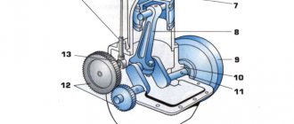
The design of a turboprop engine and the principle of its operation
The design of the motor is very simple. It includes:
- gearbox;
- air propeller;
- the combustion chamber;
- compressor;
- nozzle.
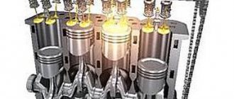
The diagram of a turboprop engine is as follows: after being pumped and compressed by a compressor, the air enters the combustion chamber. Fuel is injected there too. The resulting mixture ignites and creates gases, which, when expanded, enter the turbine and rotate it, and it, in turn, rotates the compressor and propeller. Unspent energy exits through the nozzle, creating jet thrust. Since its value is not significant (only ten percent), a turboprop engine is not considered a turbojet.
The principle of operation and design, however, are similar to it, but the energy here does not completely exit through the nozzle, creating jet thrust, but only partially, since the useful energy also rotates the propeller.
Notes[ | ]
- Il-114-300 - turboprop regional aircraft | Aviation of Russia (Russian). aviation21.ru. Date accessed: November 25, 2021.
- A.A. Gulya, D.S. Mikhailov, Y.K. Nerzhavin, S.A. Somov, V.V. Filippov.
To the pilot about a turboprop aircraft / Under the general. ed. V.V. Filippova. - Moscow: Order of the Red Banner of Labor Military Publishing House of the USSR Ministry of Defense, 1971. - P. 3. - 330 p. - V. M. Korneev.
Design features of gas turbine engines. — 2021. — ISBN 978-5-4485-9499-1. - ↑ 1 2
Inventions of Russia // Gas turbine engine
(unspecified)
. rus-eng.org. Access date: February 16, 2021. - 8. Airplanes with turboprop engines. Jet aircraft of the Second World War.
- History of the development of gas turbine engines (undefined)
. studentopedia. Access date: February 16, 2021.
Working shaft
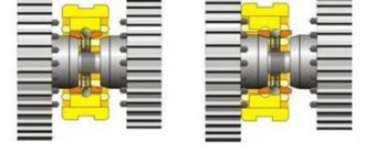
There are motors with one or two shafts. In the single-shaft version, the compressor, turbine, and propeller are located on one shaft. In a two-shaft type, a turbine and a compressor are installed on one of them, and a propeller through a gearbox is installed on the other. There are also two turbines connected to each other in a gas-dynamic way. One of them is for the propeller, and the other is for the compressor. This option is the most common, since energy can be applied without starting the propellers. And this is especially convenient when the plane is on the ground.
Recommendations
Notes
Bibliography
- Green, W. and Cross, R. Jets of the World
(1955). London: Macdonald - Gunston, Bill (2006). Jet and Turbine Aircraft Engine Engineering, 4th Edition
. Sparkford, Somerset, England, UK: Patrick Stevens, Haynes Publishing. ISBN 0-7509-4477-3. - Gunston, Bill (2006). World Encyclopedia of Aircraft Engines, 5th Edition
. Phoenix Mill, Gloucestershire, England, UK: Sutton Publishing Limited. ISBN 0-7509-4479-X. - James, D. N. Gloucester Aircraft since 1917
(1971). London: Putnam & Co. ISBN 0-370-00084-6
Air propeller
Thanks to this part, thrust is generated, but the speed is limited. The best indicator is considered to be a level from 750 to 1500 rpm, since as it increases, the efficiency will begin to fall, and the propeller, instead of accelerating, will turn into a brake. The phenomenon is called the “locking effect.” It is caused by the propeller blades, which at high speeds when rotating above the speed of sound begin to function incorrectly. The same effect will be observed when their diameter increases.
Aviation gas turbine engine Klimov GTD-350 for the Mi-2 helicopter
The development of the GTD-350 first began in 1959 at OKB-117 under the leadership of designer S.P. Izotov. Initially, the task was to develop a small engine for the MI-2 helicopter.
MI-2
At the design stage, experimental installations were used, and the node-by-unit finishing method was used. In the process of research, methods for calculating small-sized bladed devices were created, and constructive measures were taken to dampen high-speed rotors. The first samples of a working model of the engine appeared in 1961. Air tests of the Mi-2 helicopter with GTD-350 were first carried out on September 22, 1961. According to the test results, two helicopter engines were torn apart, re-equipping the transmission.
The engine passed state certification in 1963. Serial production opened in the Polish city of Rzeszow in 1964 under the leadership of Soviet specialists and continued until 1990.
The domestically produced small gas turbine engine GTD-350 has the following performance characteristics:
— weight: 139 kg; — dimensions: 1385 x 626 x 760 mm; — rated power on the free turbine shaft: 400 hp (295 kW); — free turbine rotation speed: 24000; — operating temperature range -60…+60 ºC; — specific fuel consumption 0.5 kg/kW hour; — fuel — kerosene; — cruising power: 265 hp; — takeoff power: 400 hp.
For flight safety reasons, the Mi-2 helicopter is equipped with 2 engines. The twin installation allows the aircraft to safely complete the flight in the event of failure of one of the power plants.
The GTE-350 is currently obsolete; modern small aircraft require more powerful, reliable and cheaper gas turbine engines. At the present time, a new and promising domestic engine is the MD-120, produced by the Salyut corporation. Engine weight - 35 kg, engine thrust 120 kgf.
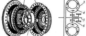
General scheme
The design of the GTD-350 is somewhat unusual due to the location of the combustion chamber not immediately behind the compressor, as in standard models, but behind the turbine. In this case, the turbine is attached to the compressor. This unusual arrangement of components reduces the length of the engine power shafts, therefore reducing the weight of the unit and allowing for high rotor speeds and efficiency.
During engine operation, air enters through the VNA, passes through the axial compressor stages, the centrifugal stage and reaches the air collecting scroll. From there, through two pipes, air is supplied to the rear of the engine to the combustion chamber, where it reverses the direction of flow and enters the turbine wheels. The main components of the GTD-350 are: compressor, combustion chamber, turbine, gas collector and gearbox. Engine systems are presented: lubrication, control and anti-icing.
The unit is divided into independent units, which makes it possible to produce individual spare parts and ensure their quick repair. The engine is constantly being improved and today its modification and production is carried out by Klimov OJSC. The initial resource of the GTD-350 was only 200 hours, but during the modification process it was gradually increased to 1000 hours. The picture shows the general mechanical connection of all components and assemblies.
Turbine
The turbine is capable of reaching speeds of up to twenty thousand revolutions per minute, but the propeller cannot match it, so there is a reduction gear that reduces the speed and increases the torque. Gearboxes can be different, but their main task, regardless of type, is to reduce speed and increase torque.
It is this characteristic that limits the use of turboprop engines in military aircraft. However, developments to create a supersonic engine do not stop, although they are not yet successful. To increase thrust, a turboprop engine is sometimes equipped with two propellers. The principle of operation is realized by rotating in opposite directions, but using one gearbox.
As an example, we can consider the D-27 engine (turbopropfan), which has two propeller fans attached to a free turbine by a gearbox. This is the only model of this design used in civil aviation. But its successful use is considered a big leap in improving the performance of the motor in question.
Compressor
The turbojet compressor has a stepped design, the number of stages varies from 2 to 6. Thanks to this system, the engine works better with temperature and pressure changes, thanks to which the pilot can easily adjust the engine speed. This design not only allows the motor to work better, but also, due to the stepped system, it is possible to lighten the weight of the motor.
This feature is very important for aviation, since the weight of the aircraft is also reduced, and due to this it is possible to reach the required speed and fly over longer distances, since fuel costs depend on the weight of the aircraft. The compressor contains: impellers with blades and a guide vane.
There are several types of apparatus, the first is adjustable; blades are installed in the guide apparatus, with which it can be rotated around its axis. And the second option does not have the ability to regulate.
Advantages and disadvantages
Let us highlight the pros and cons that characterize the operation of a turboprop engine. The advantages are:
- low weight compared to piston units;
- efficiency compared to turbojet engines (thanks to the propeller, the efficiency reaches eighty-six percent).
However, despite such undeniable advantages, jet engines in some cases are a more preferable option. The speed limit of a turboprop engine is seven hundred and fifty kilometers per hour. However, for modern aviation this is very little. In addition, the noise generated is very high, exceeding the permissible values of the International Civil Aviation Organization.
Therefore, the production of turboprop engines in Russia is limited. They are mainly installed in aircraft that fly long distances and at low speeds. Then the application is justified.
However, in military aviation, where the main characteristics that aircraft must have are high maneuverability and silent operation, and not efficiency, these engines do not meet the necessary requirements and turbojet units are used here.
At the same time, developments are constantly underway to create supersonic propellers in order to overcome the “locking effect” and reach a new level. Perhaps, when the invention becomes a reality, jet engines will be abandoned in favor of turboprops and in military aircraft. But at present they can only be called “workhorses”, not the most powerful, but stably functioning.
Hello!
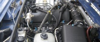
Transport aircraft AN-8 with AI-20 engines.
Today we continue to talk in more detail about the types of aircraft engines. The next type on the agenda is a turboprop engine (TVD). Anyone who has read my article here, of course, knows that a turboprop engine is a type of gas turbine engine.
A gas turbine engine is a heat engine and, like any heat engine, it has an expansion device, which is a turbine. Well, a turbine is needed, first of all, to rotate the compressor, and secondly, to drive various additional units, that is, the payload. This could be, for example, an electric generator, a propeller in a ship's installation, and in relation to aviation, an air propeller or an auxiliary power unit (APU).
However, an intermediate option is also possible. That is, part of the free energy (larger) can be used for the payload, and the remaining part (smaller) for work in the nozzle, that is, to produce jet thrust. This is precisely the principle on which a turboprop engine . Its payload is the aforementioned propeller. To be fair, it should be said that jet thrust plays a small role in the theater of operations. Its share is usually no more than 15% (in modern theaters it is even less).
Basic design of a turboprop engine.
Animation showing the operating principle of the theater.
Like everything in this world