In 1980, the Izhevsk Machine-Building Plant launched the IZH Jupiter 4 road motorcycle for mass production. The fourth generation replaced its predecessor IZH Jupiter 3 on the production line and was produced until 1986.
Jupiter 4 could confidently move on roads with any surface, and its key feature was the ability to be used together with a passenger side trailer, which made it possible to transport two passengers at once or use the trailer to transport small loads.
It is the increased passenger capacity that has become an important component of the popularity of motorcycles. In addition, it had the following advantages:
- good dynamic characteristics;
- ease of repair;
- high cross-country ability;
- affordable price;
- high reliability;
- low sensitivity to fuel quality.
The existing disadvantages of IZH Jupiter 4, according to reviews from owners, include:
- poor assembly quality at the factory (connections not tightened, poor contacts, oil leaks);
- violation of synchronization in the operation of the engine cylinders;
- poor wiring diagram;
- frequent overheating of the engine when fully loaded in warm weather.
But due to the corresponding advantages, the motorcycle was most popular among rural residents as a universal vehicle.
Motorcycle Features
The IZH Plante 5 motorcycle has the original name IZH 7.107. Just like the IZH 6, it belongs to the middle class of motor vehicles, designed for movement on roads with any surface. The main feature is the use of an oil pump; when refueling there is no need to add oil to the tank, as well as a contactless ignition system that operates independently of the battery.
It became possible to start a motorcycle from a pusher. To do this, you need to turn on the ignition, second gear and, when pushing the bike forward, the engine starts. True, without a battery, operation is possible only during daylight hours.
The Fifth Planet can be equipped with a cargo trailer and a passenger stroller. To reduce the clutch release effort, the bike has a clutch consisting of 7 pairs of discs. Vibration dampers are installed on the cylinder ribs. An important feature of this series is the presence of hydropneumatic suspension with disc brakes, which contributed to a smooth ride. The power is 22 horsepower, the maximum possible speed is 120 km/h. The volume of the two-stroke single-cylinder engine is 346 cm3. The power unit has good traction at low speeds.
Technical characteristics of the motorcycle
Despite some shortcomings in the electrical circuit of the motorcycle, its design, advantages and technical characteristics were the main factors in the popularity of the IZH Jupiter 4. Among the key characteristics and parameters, it is necessary to highlight:
- Passenger capacity – 3 people.
- Engine: type – petrol two-stroke,
- fuel – a mixture of gasoline and oil (1/33),
- type of lubricant – mixed,
- cooling method - air,
- number of cylinders – 2,
- volume – 0.35 l,
- power – 28.0 l. With.
- length – 2.17 m,
- type – mechanical,
- weight – 0.17 t (0.26 t),
Electrical equipment IZH Planet 5
Motorcycles IZH 3, 4, 5 and 6 are equipped with 12-volt electrical equipment. The wiring of IZH Planet 3 and 5 consists of standard 12-volt incandescent lamps, a set of instruments and switches.
The electrical wiring is single-wire, there is no negative wire, its role is played by the bike frame. Planet 4 is similar to the electrical circuit of Planet 5.
The electrical circuit includes the following main components:
- generator;
- turns and side lighting;
- Headlight;
- contactless ignition system.
The power source on both IZh 5 and 6 motorcycles is a battery and a 3-phase alternating current generator. In the generator, alternating current from the windings is supplied to the rectifier and converted into direct current. Power is supplied to all consumers through the ignition switch (video author: altevaa TV).
The head light circuit of the IZH Planet 5 motorcycle consists of: a headlight bulb, a blue turn-on indicator light, a parking light bulb, and a rear brake light bulb.
The following control devices are installed on the bike:
- tachometer, on which there are indicator lights for the headlights and turns;
- speedometer showing total and daily mileage;
- power engine temperature indicator;
- voltmeter.
Engine IZH Jupiter
In 1961, an Izhevsk motorcycle called Jupiter was released. A new family of IZH Jupiter has appeared. The design is similar to the IZH-56 motorcycle produced earlier. Its significant difference is the installation of a two-cylinder engine. In addition, some changes have been made to the clutch, gear shift device and electrical equipment. At the front of the crankcase there are two crank chambers, and at the rear there is a gearbox. The crank chambers are closed with covers and each of them contains crankshafts on ball bearings, which are protected from axial displacement by retaining rings. The crankshaft axle shafts are sealed with oil seals. Under the left crankcase cover mounted on a gasket, the front chain drive, clutch and trigger mechanism are located. The crankshafts are connected to each other by an external flywheel. The generator rotor and the breaker cam are installed on the axle cone of the right crankshaft. The generator housing is mounted on the crankcase. The engine pistons are connected to the crankshaft connecting rods using piston pins, which are protected from axial displacement by retaining rings. The engine cylinders have aluminum jackets and cast iron liners. The cylinder heads are made of aluminum alloy and are attached together with the cylinders to the crankcase with studs.
Engine part of IZH Jupiter
The motor part of the engine consists of a cylinder-piston group, a crank mechanism and a crankcase group.
Motor part of IZH Jupiter: 1 – generator cover; 2 – right crankcase cover; 3 – generator; 4 – right seal with cover; 5 – right crankshaft; 6 – right half of the crankcase; 7 – flywheel; 8 – crankshaft seal; 9 – crank chamber cover; 10 – left crankshaft; 11 – left seal; 12 – left half of the crankcase; 13 – crankshaft sprocket; 14 – left crankcase cover; 15 – cylinder; 16 – cylinder head; 17 – piston; 18 – spark plug; 19 – connecting rod; 20 – hairpin.
Engine parts IZH Jupiter
Engine parts: 1 – cylinder pipe; 2 – cylinder gasket; 3 – left cylinder; 4 – hairpin; 5 – left cylinder head; 6, 12 – washers; 7 – nuts; 8 – retaining ring; 9 – piston; 10 – piston ring; 11 – left cheek of the crankshaft; 13 – connecting rod; 14 – right cheek of the crankshaft; 15 – flywheel; 16 – bushing; 17 – piston pin; 18 – crankshaft; 33 – flywheel mounting bolt; 34 – crank pin; 35 – needle bearing.
Clutch IZ Jupiter
Located on the left side of the engine in an oil bath. Closed with a lid with a gasket to prevent oil leakage. The main thing that can be said when assembling the coupling. Some conditions need to be met. The first compression spring nuts should protrude 3.5 - 4.0 mm above the caps. This will save the disks from distortion. Tighten the second adjusting screw until it stops. Then loosen 1/4…1/2 turn. Essentially this is a clutch adjustment.
Details of the Izh Jupiter clutch: 19 – bracket with lever; 20 – outer clutch drum; 21 – pusher; 22 – ball; 23 – thrust rod; 24 – inner clutch drum; 25 – clutch drive disk; 26 – driven disk; 27 – pressure disk; 28 — cap; 29 – spring; 30 – shaped nut; 31 – adjusting screw; 32 – nut.
IZ Jupiter clutch diagram
The clutch of the IZH-Jupiter motorcycle differs from the clutch of the IZH-56 motorcycle by the installation of a ball bearing and an adjusting screw 31 with a lock nut 32.
IZ Jupiter trigger mechanism
The starting mechanism is designed to start the engine. Has no adjustments. The parts are simply assembled in the right position and that’s it. During operation, worn parts are replaced with new ones. The gears and sector are the first to fail - inspect the teeth.
Starting mechanism of the IZH Jupiter motorcycle: 1 - washer; 2 — trigger pedal; 3 - roller; 4 — pedal axis; 5 - ball; 6 — clamp spring; 7 - clamp; 8 - bolt; 9 — reflector; 10 - cuff; 11 — kickstarter shaft; 12 - sector; 13 - spring; 14 — washer; 15 - ring; 16 — washer; 17 — spring; 18 - gear.
Gear shift mechanism IZ Jupiter
It is located inside the gearbox and the control lever is on the left side of the engine. It has changed the drive device of the shift sector and forks, which operate directly on the worm shaft. If the switch does not work properly. Disassemble the engine and wash all switching parts and check for wear and chips. Replace faulty ones.
IZ Jupiter gear shift mechanism: 4 – shift pedal; 25 – spring of the gear shift mechanism; 26 – gear shift sector; 27 – mechanism leash; 28 – shaft; 32 – worm shaft; 33 – fork for switching second and fourth gears; 34 – fork for shifting first and third gears; 36 – clamp spring; 37 – neutral contact post; 38 – neutral contact flag; 39 – switching anchor.
Gearbox IZH-Jupiter
The gearbox of the IZH-Jupiter motorcycle on the IZH-Yu motorcycle is the same as on the IZH-56 motorcycle and differs only in the design of the switching mechanism. Basic care is checking the oil and replacing it in a timely manner.
IZ Jupiter gearbox diagram: 1 – input shaft; 2 – secondary shaft; 3 – intermediate shaft; 4 – support ball bearings of the shafts; 5 – roller bearing of the secondary shaft; 6 – gearbox gears; 7 – secondary shaft oil seal; 8 – asterisk.
IZ Jupiter engine diagram
Diagram of the engine block with gearbox, clutch and generator: 1 – spark plug; 2 – cylinder head; 3 – cylinder; 5 – piston; 6 – piston ring; 7 – bypass channel; 8 – piston pin; 9 – bushing of the upper head of the connecting rod; 10 – connecting rod; 11 – left crank chamber cover; 12 – drive sprocket; 13 – ball bearing; 14 – oil seal; 15 – left crankshaft axle shaft; 16 – roller bearing of the lower head of the connecting rod; 17 – crank pin; 18 – clutch spring; 19 – hatch cover; 20 – clutch adjusting screw; 21 – clutch pressure plate; 22 – inner drum; 23 – gear shift pedal; 24 – trigger pedal; 25 – left crankcase cover; 26 – clutch discs; 27 – outer clutch drum; 28 – trigger mechanism sector; 29 – spring; 30 – trigger gear; 31 – ball bearing; 32 – left half of the crankcase; 33 – gear shift fork; 34 – gear shift roller; 35 – gear shift sector; 36 – gear shift mechanism roller; 37 – fastening pin; 38 – right half of the crankcase; 39 – right cylinder head; 40 – right cylinder; 41 – flywheel; 42 – right crank chamber cover; 43 – cylinder gasket; 44 – right oil seal; 45 – generator; 46 – right crankshaft axis; 47 – right crankcase cover; 48 – generator cover; 59 – breaker cam; 50 – central anchor mounting bolt; 51 – asterisk; 52 – oil seal; 53 – roller bearing; 54 – secondary shaft; 55 – oil seal; 56 – input shaft; 57 – clutch release rod; 58 – clutch release lever; 59 – sprocket mounting nut; 60 and 61 – gearbox gears; 62 – clutch cable cam; 63 – clutch cam; 64 – spring.
Maintenance
Those who love their bike regularly monitor its technical condition. During operation, it is sometimes necessary to adjust the gap between the breaker contacts. To carry out this operation, you need an electrical diagram of the IZH 5 motorcycle, which shows the connection of devices, and the corresponding tools.
The procedure consists of the following steps:
- The motorcycle should be placed on the stand and put in neutral.
- Next you need to unscrew the spark plugs.
- Then remove the cover from the crankcase.
- At the next stage, you need to ensure that the contacts are as open as possible. To do this, we need to turn the crankshaft.
- Next, you need to loosen the locking screw using a screwdriver.
- Using a feeler gauge, the gap should be set to 0.35-0.45 mm. Fix the gap with a screw.
- We do the assembly in reverse order.
When the clearance is correctly set, the engine idles stably.
The electrical circuit of IZH 3, 4, 5 and 6 is quite simple and any driver can figure it out in order to repair it with his own hands if necessary.
This need may arise in the following cases:
- operating the bike in wet weather (contacts oxidize);
- movement through areas overgrown with vegetation (mechanical damage to wiring);
- trips in winter (dirt sticks, which can damage the wiring).
On both IZH 5 and 6 bikes there may be problems with the sound signal; it may sound weaker. To adjust it, you need to loosen the lock nut, turn on the ignition and use a screwdriver to adjust the tone. Once the desired tone is achieved, the locknut must be tightened.
The road version of the IZH Planet 5 motorcycle differed favorably from other domestic analogues by the use of an oil pump, which made it possible to abandon the scheme for pre-mixing fuel with oil.
In addition, subsequent modifications were distinguished by their contactless ignition system, independent of the battery, and modified kinematics.
This allowed:
- To set the motorcycle in motion “from the pusher” - by turning on the ignition, the owner engaged second gear and, using his own efforts, pushing the motorcycle forward, started the engine;
- Operation without a battery was possible during daylight hours (a battery was still required for the side lights and headlights to operate).
Specifications
- Weight – from 160-250 kg;
- Dimensions – 1540-1550x2200-2400 mm;
- Engine power – 15,000 W, 20 hp;
- Maximum load – 300-320 kg;
- Synchronization with a smartphone – no;
- Depreciation – present;
- Cross-country ability on one charge – from 50-250 kilometers;
- There is a protective frame.
Motorcycle Features
According to industry norm, the motorcycle had an alphanumeric index:
- IZH 7.107-010 – basic model;
- IZH 7.107-020 was already equipped with a new lubrication system and improved front axle suspension. In addition, the wiring diagram of the IZH Planet 5 motorcycle had a contactless ignition system, independent of the battery;
- IZH 7.107-030 was equipped with a spring-hydraulic shock absorber and a redesigned rear wheel brake drive;
- IZH 7.107-040 was produced with modified kinematics and a modified front wheel brake. The wiring diagram on IZH Planet 5 remained contactless until 2008.
In addition, a side trailer (sidecar) or a universal cargo platform (without a seat) could be attached to the motorcycle.
Posts
About the motorcycle
Cafe-racer based on IZH-P5. Built in the FCF (Froloff Custom Forged) workshop. Received the name BlackSmith after painting. Exclusive painting in vintage style - matte black, some elements in gold, patina. The frame is originally from Yu3. I’ve never seen the standard (it was once rebuilt before me - tapered bearings were installed in the fork and the pendulum was lengthened and switched to roller bearings; a person took part in motocross on this frame with a K11 engine). All excess has been removed, the frame has been welded with argon (including factory seams), and heat-treated. Custom FCF dual variable spring monoshock, bare chain, chain sliders, custom FCF drive and rear brakes. Rear wheel travel is 240-200 mm (depending on adjustments), ground clearance is 31 cm over the muffler. Fork based on IZH - strengthened springs, valves and custom FCF guides, rebound springs, custom FCF oil seal assembly, polished fork crowbars. Boosted engine from the category “so that you can live happily ever after”))): intake and exhaust porting, milled head, slight change in the shape of the combustion chamber, SZh 11.6 (AI-95 only), forged piston to order with modified geometry, NGSh repressed on the needle SNR, lightening and centering of the HF, lightweight connecting rod with a modified shape. Rings chrome. The motor is assembled on SNR, SKF bearings, and foreign seals. The P5 gearbox is stock, the gear pairs are ground in. Experimental clutch by custom FCF based on a reinforced IZH-P5 motor transmission with CZ, Honda components (I will reveal the details after full tests). Custom FCF exhaust (quarter-wave resonator, Blair design, muffling system similar to LeoVinci quarter-wave resonators). Estimated power 38 l/s. Carb is temporarily K68I “baker”. GTZ 350. Waiting for Keihin))) Tank from P5, fuel sensor on the tank, overcooked for a lower landing. Hump based on a Jawa 634 custom FCF tank, custom FCF saddle, upholstery made in black eco-leather, voluminous cage. Custom FCF fenders based on Jawa 634 rear fenders. Hidden electrics, and much more... Project under construction! The project is not being built for the sake of “dumping in”, but for the soul and pleasure. It is built not as a “show stopper”, but as a moto for constant use. The project promises to be interesting. Subscribe, follow. Details in the BZ. It will not be boring!
Passport details
Volume From 251 to 600 cm³ Max. power 36 hp Year of manufacture 2020 Year of purchase 2020
Electrical equipment IZH Planet 5
The motorcycle uses 12-volt electrical equipment. The electrical wiring of the IZH Planet 5 motorcycle is single-wire, the role of the negative wire is performed by a metal frame.
Among the main components are:
- Power supplies;
- Ignition system;
- Headlight;
- Side lighting and turns.
For reference: as is customary in auto and motorcycle construction, modification of components and assemblies allows you to reduce the cost of products. For consumers, the advantage is that the price is low and a number of parts are interchangeable.
Generator
The motorcycle is equipped with a three-phase alternating current generator with an electromagnetic excitation circuit.
The principle of its operation is as follows:
- Electric current from the windings located on the stator is supplied to the rectifier;
- It converts it to direct current;
- And supplies it to consumers through the ignition switch.
The instructions provided include the following items:
- Voltage regulator with rectifier BPV-14-10;
- Generator rotor;
- Generator stator with windings;
- Current collector brushes;
- Ignition system cam (battery);
- Ignition system contact unit
For reference: on three-phase generators of the IZH Planet 5 motorcycle, the windings are connected according to a “star” or “delta” circuit. The rectifier is installed as a separate unit, and the IZH Planet 5 electrical wiring is connected to it.
Headlight
For reference: with such a generator, IZH Planet 5 did not need an external current source when starting the engine. Therefore, the battery was not included in the electrical equipment.
The head light circuit includes:
- headlight lamp (35W);
- blue indicator lamp (2W);
- headlight parking light (4W);
- rear brake light lamp (15W).
Control devices
The following control devices are installed on the motorcycle:
- speedometer with daily and total mileage counters;
- tachometer with indicator lamps for direction indicators and headlights;
- engine temperature indicator;
- voltmeter.
Patency
The official source stated that such an electric motorcycle will be presented to the whole society, since it is capable of moving across various landscapes, and we know very well what conditions and roads can be like in Russia. It can be used both for travel purposes and for any professional activity - construction sites, repair locations, and so on.
We recommend:
- Kawasaki electric motorcycle: review, its characteristics, capabilities and cost
- Electric motorcycle Z1000: characteristics, pros and cons, price
- Soco electric motorcycle: review of the electric motorcycle, characteristics and cost
Maintenance Features
Often during operation it is necessary to correctly set the gap between the contacts of the breaker. To do this, you need tools and a diagram to see which elements need to be dismantled.
The algorithm of actions is as follows:
- place the motorcycle on the stand;
- turn on neutral;
- unscrew the spark plug from the cylinder;
- remove the engine crankcase cover;
- turn the crankshaft until the contacts are as open as possible;
- using a screwdriver, loosen the locking screw;
- using a special feeler gauge, set the gap to 0.35-0.45 mm and fix it with a screw;
- we collect everything in reverse sequence;
- turn on the ignition and start the engine. Its stable operation at idle indicates that the adjustment has been correctly performed.
In general, all the wiring of IZH Planet 5 is very easy to do with your own hands.
The need for such work often arises when operating a motorcycle:
- in wet weather, driving in the rain for a long time (oxidation or dampness of electrical contacts);
- when traveling over rough terrain, replete with vegetation and bushes (mechanical damage to wiring);
- when used in winter (snow and slush stick to the wires and can damage them).
Often the sound signal suffers during operation. Its malfunctions manifest themselves in the form of deterioration in sound quality.
To restore its functionality, you must perform the following procedure:
- loosen the locknut using an open-end wrench;
- turn on the ignition;
- press the button to turn on the sound signal;
- use a screwdriver to adjust the tone;
- repeat the procedure until we get a clear and loud sound;
- tighten the control nut.
Conclusions: we are confident that this article will help you in servicing motorcycles of the IZH family (see also the article about). Both the attached diagrams and description will help you avoid making mistakes during operation.
While easily fixing mechanical failures, motorcyclists experience difficulties if the electrics fail. It’s completely in vain, the wiring diagram of the planet Izh 5 is not complicated, it’s easy to figure out.
There is no need to have special stands and equipment for repairs. A minimum knowledge of electrical engineering and a simple avometer (tester) is enough; even often you can get by with just a test lamp.
We will tell you in more detail about the main electrical wiring components and possible malfunctions. Finding a broken wire or damaged insulation is easy (for example, a bad contact always gets hot).
But pay special attention to the fact that the electrical circuit is designed not only for 12 volts, there is also a high-voltage cable (connecting the coil and the spark plug), which cannot be checked with a regular ohmmeter.
In this case, we look to see if there is a spark at the coil output and at the output at the spark plug contact. Now in detail about the main wiring components of the Izh Planet.
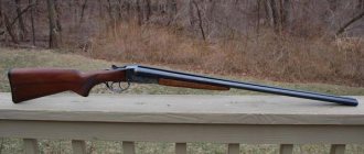
Passport for hunting rifle IZH-27
1.1. When starting to use the gun, carefully study the passport. This passport briefly introduces the main technical characteristics, design and operating rules of the gun. 1.2. Designations of parts and assembly units are shown in the figures and in the corresponding tables. 1.3. When purchasing a gun, please fill out a passport: the name and address of the trade organization that sold the gun, the date of sale, the store stamp and the seller’s signature - otherwise the company will not accept claims. 1.4. Send comments on quality and wishes to the address: 426063, Izhevsk, st. Promyshlennaya, 8, State Enterprise "Izhevsk Mechanical Plant". 2. PURPOSE 2.1. Double-barreled hunting shotguns IZH-27M, IZH-27EM, their versions with a single trigger mechanism (marking: IZH-27M-1S, IZH-27EM-1S) with a chamber of 76.2 mm (marking: IZH-27M-M, IZH-27EM- M, IZH-27M-1S-M, IZH-27EM-1S-M) are intended for various types of hunting with hunting cartridges with a cartridge case length of up to 70 mm. Shotguns with a 76.2 mm chamber are also designed to fire hunting cartridges with a case length of up to 76 mm. Note. The IZH-27EM shotgun differs from the IZH-27M by the presence of a mechanism for automatically ejecting cartridges.
3. TECHNICAL CHARACTERISTICS 3.1. The main parameters and their values are given in table. 1. 3.1.1. 12 gauge shotguns may come with interchangeable choke tubes. Nominal value of the narrowing of the choke nozzles, mm: 1.25; 1.0; 0.75; 0.5; 0.25; 0.0. 3.2. The gun has been tested for accuracy and meets technical specifications. Note. Accuracy of fire is assessed on a target with a diameter of 750 mm using cartridges with solid shot with a diameter of 2.5 mm (c 7). Accuracy indicators for firing cartridges with a case length of up to 70 mm from barrels with chambers of 70 mm and 76.2 mm must correspond to Table 1a. For piece guns, the accuracy of fire from each barrel is 5% higher. For shotguns with a chamber length of 76.2 mm, the accuracy of fire with hunting cartridges with a case length of 76 mm must be at least 40%. No more than three shots are fired from each barrel and, if one of them gives the specified result, the barrel engagement is considered satisfactory. Table 1
| Parameter name | Parameter value | ||||||||
| Caliber | 12 | 16 | 20 | 28 | 32 | 12 | 20 | .410 | |
| "Magnum" | |||||||||
| Length, nominal value, mm | chamber | 70 | 76,2 | ||||||
| trunk | 675, 725, 750 | 725 | 675 | 725 | 675 | ||||
| Barrel bore diameter, nominal value, mm | 18,4 | 17 | 15,7 | 14 | 12,5 | 18,4 | 15,7 | 10,3 | |
| Muzzle constriction, nominal value, mm* | upper barrel F (choke) | 1,0 | 0,6 | 1,0 | 0.5 | ||||
| lower trunk M (pay) | 0,5 | 0,3 | 0,5 | 0,25 | |||||
| Average value of the maximum gas pressure developed by cartridges during weapon operation, MPa (kgf/cm2), ns more | 65 (663) | 68 (694) | 72 (734) | 90 (918) | |||||
| Weight of the gun, kg, ns more | 3,4 | 3,2 | 3,1 | 3,6 | 3,3 | 3,1 | |||
Note - *It is possible to manufacture guns with other combinations of choke constrictions. The type of restrictions and their nominal values are indicated on the barrels.
Table 1a
| Marking designation on the barrel | DR | WITH | 1C | M | 1M | F | T |
| Firing distance, m | 20 | 20 | 35 | 35 | 35 | 35 | 35 |
| Accuracy, %, not less | 65 | 65 | 40 | 50 | 55 | 60 | 65 |
3.3. The gun is suitable for firing smoky and smokeless powders. Sleeves can be used paper, metal and plastic. 3.4. Guns can be supplied in standard, piece and export versions.
INFORMATION ABOUT THE CONTENT OF PRECIOUS MATERIALS IN SINGLE GUNS
| Name | Designation | Assembly units, complexes, kits | Weight of 1 pc. | Product weight | Act number | Note | ||
| designation | quantity | quantity per product | ||||||
| Silver | ||||||||
| Chemical engraving | ||||||||
| Box Larva | IZH-273-1 | IZH-27 Sat | 1 | 1 | 0.866 g | |||
| Hand engraving | IZH-12 3-37 | IZH-27 Sat | 1 | 1 | 0.253 g | 1.119 g | ||
| Box | IZH-273-1 | IZH-27 Sat | 1 | 1 | 1.012 g | |||
| Larva | IZH-273-1 | IZH-27 Sat | 1 | 1 | 0.306 g | 1.318 g | ||
4. PRODUCT COMPOSITION AND COMPLETENESS
Rice. 1. Details of the IZH-27M gun.
4.1. The list of assembly units and parts of the IZH-27 M gun is given in table. 2.
table 2
| Designation in Fig. 1 | Name | Quantity per product |
| 1 | 2 | 3 |
| 1 | Trunks collected | 1 |
| 2 | Ejector | 1 |
| 3 | Screw | 1 |
| 4 | Front sight | 1 |
| 5 | Swivel ring | 2 |
| 6 | ' Axis | 2 |
| 7 | Hinge assembled | 1 |
| 8 | Handguard | 1 |
| 9 | Screw | 1 |
| 10 | Forend bushing | 1 |
| 11 | Latch body | 1 |
| 12 | Forend latch | 1 |
| 13 | Pin | 1 |
| 14 | Spring | 1 |
| 15 | Box | 1 |
| 16 | Lock lever | 1 |
| 17 | Screw | 1 |
| 18 | Lock lever axis | 1 |
| 19 | Locking plate | 1 |
| 20 | Return spring | 1 |
| 21 | Upper striker | 1 |
| 22 | Bottom striker | 1 |
| 23 | Striker spring | 2 |
| 24 | Right trigger assembled | 1 |
| 25 | Left trigger assembled | 1 |
| 26 | Axis | 1 |
| 27 | Combat spring rod | 2 |
| 28 | Combat spring | 2 |
| 29 | Right sear | 1 |
| 30 | Left sear | 1 |
| 31 | Axis | 3 |
| 32 | Spring | 2 |
| 33 | Pusher right | 1 |
| 34 | Left pusher | 1 |
| 35 | Safety button | 1 |
| 36 | Fuse base | 1 |
| 37 | Fuse | 2 |
| 38 | Axis | 3 |
| 39 | Spring | 2 |
| 40 | Spring | 1 |
| 41 | Earring | 1 |
| 42 | Pin | 1 |
| 43 | Engine | 1 |
| 44 | Interceptor | 2 |
| 46 | Spring | 2 |
| 47 | Screw | 1 |
| 48 | Jumper | 1 |
| 49 | Larva | 1 |
| 50 | Screw | 1 |
| 51 | Striker delay | 1 |
| 52 | Spring | 1 |
| 53 | Axis | 1 |
| 54 | Right trigger | 1 |
| 55 | Left trigger | 1 |
| 56 | Axis | 2 |
| 57 | Trigger pull | 2 |
| 58 | Platooner | 2 |
| 59 | Axis | 2 |
| 60 | Safety bracket | 1 |
| 61 | Screw | 1 |
| 62 | Butt | 1 |
| 63 | Screw | 1 |
| 64 | Washer | 1 |
| 66 | Butt butt | 1 |
| 67 | Screw | 1 |
| 68 | Screw | 1 |
| 69 | Swivel base | 1 |
| 70 | Screw | 1 |
| 71 | Screw | 1 |
| 72 | Washer | 2 |
4.2. The list of assembly units and parts of the IZH-27EM gun is given in table. 3.
Table 3
| Designation in Fig. 2 | Name | Quantity per product |
| 1 | Trunks collected | 1 |
| 2 | Ejector right | 1 |
| 3 | Left ejector | 1 |
| 4 | Ejector spring | 2 |
| 5 | Gnetok | 2 |
| 6 | Hinge assembled | 1 |
| 7 | Handguard | 1 |
| 8 | Right ejector sear | 1 |
| 9 | Left ejector sear | 1 |
| 10 | Ejector sear axis | 2 |
| 11 | Spring | 2 |
| 12 | Box | 1 |
| 13 | Pusher right | 1 |
| 14 | Left pusher | 1 |
| 15 | Disconnector | 2 |
| 16 | Disconnector lock | 2 |
| 17 | Spring | 2 |
Note. The remaining parts do not differ from those of the IZH-27M gun.
Rice. 2. Details of the IZH-27EM gun.
4.3. The list of assembly units and parts of the IZH-27M-1S, IZH-27EM-1S shotguns is given in table. 4.
Table 4
| Designation in Fig. 3 | Name | Quantity per product |
| 1 | Leash | 1 |
| 2 | Locking plate | 1 |
| 3 | Right sear | 1 |
| 4 | Left sear | 1 |
| 5 | Inertial disconnector | 1 |
| 6 | Interceptor | 1 |
| 7 | Larva | 1 |
| 8 | Trigger | 1 |
| 9 | Translator | 1 |
| 10 | Translator spring | 1 |
| 11 | Translator axis | 1 |
| 12 | Trigger pull | 1 |
| 13 | The spring will release | 1 |
| 14 | Trigger rod spring | 1 |
| 15 | Disconnector axis | 1 |
| 16 | Trigger rod axis | 1 |
| 17 | Trigger spring | 1 |
| 18 | Spring screw | 1 |
| 19 | Interceptor spring | 1 |
Notes: 1. The remaining parts of the IZH-27M-1S do not differ from the parts of the IZH-27M gun. 2. The remaining parts of the IZH-27EM-1S do not differ from the parts of the IZH-27EM gun
Rice. 3. Parts of the IZH-27M-1S and IZH 27EM-1S shotguns.
4.4. Completeness according to table. 5.
Table 5
| Name | Quantity |
| Gun | 1 |
| Box | 1 |
| Packaging Passport | 1 |
In guns with interchangeable choke tubes, the complete set other than those indicated in the table. 5, includes: - replaceable choke tubes - 5 pcs.; — key — 1 pc.;
5. DEVICE AND PRINCIPLE OF OPERATION
Fig.4. Diagram of the ejection mechanism of the IZH-27M shotgun.
1 - ejector; 2 — upper striker; 3 — axis of the locking lever; 4 — locking lever; 5 — lower striker; 6 - box; 7 — engine; 8 - trigger; 9 - sear; 10 — fuse base; 11 — fuse spring; 12 - fuse; 13 — safety button; 14-handguard; 15- hinge; 16 - cocker; 17 - hinge axis; 18—pusher; 19-locking plate delay; 20-larva; 21 - return spring; 22-bar locking; 23 — interceptor spring; 24 - interceptor; 25 — right trigger; 26 — mainspring rod; 27 - thrust; 28 — left trigger; 29 — mainspring; 30 — safety bracket.
Rice. 5. Diagram of the ejection mechanism of the IZH-27EM gun: 31 - ejector sear; 32 - disconnection; 33 — left ejector; 34 — right ejector; 35 — ejector sear spring; 36 — release latch; 37 — clamp spring.
Rice. 6. Diagram of the single-trigger mechanism of the IZH-27M-1S, IZH-27EM-1S shotguns: 38 - interceptor; 39 — sear; 40 — descent rod axis; 41 - translator; 42 — axis disconnected; 43 — inertial disconnector; 44 - larva; 45 — locking bar; 46 — interceptor spring; 47 - trigger hook; 48-leash; 49-trigger pull; 50 — trigger rod spring; 51- disconnector spring; 52— trigger hook spring; 53 - spring screw. 5.1. Removable barrels are located in a vertical plane, connected using a coupling and interbarrel strips. The muzzle constrictions ensure stable shooting accuracy. The gun barrels are securely locked in the box by a locking bar. The locking unit is controlled using a lever located on top of the box. When the barrels are open, the locking lever is held by the locking bar, which automatically releases the lever when the barrels are closed. 5.2. The removable forend is secured with a lever-type latch. 5.3. In the IZH-27M shotgun, the cartridges are pulled out of the chambers by an ejector when the barrels are opened. The IZH-27EM shotgun has an ejection mechanism that automatically ejects the spent cartridge case. The cartridge case is ejected from the barrel from which the shot was fired. If there was no shot, the cartridge moves out smoothly. If necessary, the ejection mechanism can be easily turned off by turning the disconnector 32 (Fig. 5) by 90°, in this case the sleeves will slide out smoothly. 5.8. The trigger mechanism has an additional safety device (trigger interceptors) to prevent a shot from being fired if the triggers are accidentally released without pressing the triggers. 5.9. The IZH-27M-1S and IZH-27EM-1S shotguns (Fig. 6), unlike the IZH-27M and IZH-27EM shotguns, have one trigger for firing in the sequence: lower barrel - upper barrel. If you need to change the sequence of shots, press the trigger forward until it clicks: only two shots will change the sequence. Subsequent opening of the locking lever will restore the original sequence: lower barrel - upper barrel. 5.10. Due to the constant work to improve the gun, increasing its reliability and improving performance properties, changes may be made to the design that are not reflected in this passport.
6. SAFETY INSTRUCTIONS 6.1. Any firearm, despite the presence of various safety devices in it, poses a known danger to the life and health of people if it is handled carelessly. Therefore, even if your gun has trigger interceptors, take all precautions and remember that neglecting safety rules can lead to tragic consequences. 6.2. Always consider the gun loaded and ready to fire. 6.3. Before any actions with the gun (smooth release, cleaning, disassembling and screwing in and unscrewing choke tubes, etc.), ALWAYS make sure that the gun is unloaded. 6.4. For shotguns with interchangeable choke tubes, follow these recommendations: - complete the final screwing in of the tube with a special wrench applied to the shotgun. A correctly installed nozzle should be flush or slightly recessed relative to the muzzle of the barrel; — inspect the bore. In this case, the ring should be visible in the place where the surface of the barrel bore protrudes above the surface of the nozzle. Violation of the integrity of the ring indicates mechanical damage to the nozzle (bruises, bending of the edges) or the seat in the barrel. In this case, shooting may damage the attachment or the gun; - remember that nozzles and seats for them require careful handling in order to prevent accidental deformation of thin-walled sections. Do not leave barrels without screwed-in attachments unless necessary. 6.5. Do not fire your gun with cartridges with charges larger than those recommended on the factory package of powder, or with a mixture of black powder and smokeless powder. 6.6. Do not shoot cartridges or powder that have been stored for more than 4 years. 6.7. The use of any non-hunting powders is strictly prohibited, as this can lead to swelling or rupture of the barrels. 6.8. It is prohibited to compress a charge from smokeless hunting powder. 6.9. Do not shoot a bullet whose body diameter is greater than the diameter of the bore in the choke area. The diameter of a round bullet should be 0.2-0.3 mm less than the diameter of the muzzle. The diameter of a bullet with external ribs should be 0.1-0.2 mm less than the diameter of the bore, and the diameter of the body of such a bullet should be 0.8-1.0 mm less than the diameter of the channel at the exit (choke). 6.10. Do not put much force on the trigger to avoid damage, but cock the hammer again with the barrel fully open if, as a result of the gun falling, the cocked hammer was delayed on the interceptor. 6.11. Inspect the barrels of the gun before loading to see if they are clogged with snow, dirt, or forest debris. Shooting a gun with clogged bores can cause the barrels to swell and even burst. 6-12. Monitor the quality of your cartridges to avoid local, so-called “pea-shaped” swelling. When using metal shells, carefully secure the cardboard liner of the shotshell, use paper shells only once, and do not reload finished cartridges to avoid softening the ends of the shells. It is recommended that after firing from the lower barrel (if a shot was not fired from the upper barrel), the cartridge that was in the upper barrel is placed in the lower barrel, and the next cartridge is placed in the upper barrel.
7. MAINTENANCE 7.1. Proper handling and timely maintenance increases the service life and guarantees its reliable operation. If this is not necessary, you should not completely disassemble the gun. 7.2. To ensure the necessary care (cleaning, lubrication, inspection), the gun is partially disassembled: the barrels, the forend with a hinge and the box with the butt are separated. 7.3. When completely disassembling and reassembling the gun, you must strictly follow the instructions in this passport. 7.4. Disassembly procedure: 7.4.1. To separate the butt you must: 1) unscrew the screws and remove the back of the butt; 2) unscrew the screw securing the safety bracket to the butt, and, turning the bracket counterclockwise, separate it from the cylinder; 3) unscrew the screw passing through the butt to the back of the butt, lightly tap the box against a wooden object to slightly loosen the connection between the butt and the box, and then carefully remove the butt. After the butt is separated, the mechanisms become accessible for inspection, cleaning and lubrication. In guns with applied decorative boards, separate the butt from the box after removing the boards, for which you need to remove the screws securing the boards to the box and butt. 7.4.2. To disassemble the trigger mechanism, you must: 1) cock the hammers, insert pieces of wire or nails with a diameter of 1-1.5 mm into the hole on each mainspring rod (the hole on the rod, when the triggers are cocked, is aligned with the recess on the jumper connecting the shanks of the box and the cylinder ), pull the triggers and remove the mainspring rods with the springs; 2) use a drift to knock out the axles of the hammers and sears, remove the hammers and sears; 3) remove the fuse parts by knocking out the pin supporting the spring; 4) unscrew the lower cylinder screw and the rear tail rotor, remove the jumper. Separate the larva with light blows of a hammer on a brass or copper rod inserted into the hole for the safety bracket, while moving the larva back. 7.4.3. To disassemble the locking mechanism, you must: 1) knock out the pins of the strikers, remove the strikers with springs and unscrew the screw connecting the locking lever to the axle; 2) using a copper or brass rod, use a hammer to knock down the axis of the locking lever with the return spring and remove the locking bar. 7.4.4. To disassemble the ejection mechanism, it is necessary: 1) knock out the cocking axes and remove the cocking rods, remove the disconnector, to do this, install them with slots at an angle of 45° to the axis of the gun, insert a screwdriver or drift into the hole under the pusher and push the disconnector up; remove the retainer with the spring. If necessary, the disconnector can be removed without disassembling the box. To do this, set the disconnector slot at an angle of 45° to the axis of the gun, cock and then release the trigger, while the pusher will push the disconnector out of the box; 2) separate the ejector by pressing its front end from the barrels, after which it will come out of the groove under the action of a spring. To prevent loss of the ejector, it must be held. 7.5. Further disassembly of the mechanisms is simple and does not require special explanation. When disassembling, do not mix up the parts on the right and left sides. 7.6. The gun is assembled in the reverse order: 7.6.1. The connection between the butt and the box must be strong, without the slightest movement. To ensure the correct fit of the stock, it is recommended that after tightening the screw, lightly tap the screwdriver handle on the side surfaces of the stock head to bring them down to the corresponding surfaces of the box and then tighten the screw until it stops. 7.6.2. Before installing the forend, it is recommended to lower both cockers down (if they are raised), then, holding the gun by the barrels with your left hand, put the forend on the lower barrel with your right hand and bring the cylindrical part of the hinge into full contact with the corresponding surface of the box. In a new gun, the fore-end latch under the action of the spring may not reach its original position; move it by hand.
8. INSTRUCTIONS FOR OPERATION AND CARE OF THE GUN 8.1. The service life and trouble-free operation of a gun largely depend on skillful and careful handling of it. 8.2. The gun should always be cleaned and lightly oiled. Particular attention should be paid to the cleanliness and lubrication of the barrels, the junction of the hinge with the box, the hinge axis and the corresponding socket on the barrel coupling, the rubbing areas of the barrel and box, and parts of the trigger mechanism. 8.3. Chrome-plated bores and barrel chambers make them much easier to care for, but this does not preclude regular and thorough cleaning. 8.4. For cleaning, use soft, clean rags, tow, flax tow, and cotton ends. 8.5. The wiping material should not contain sand and dust. Clean immediately after shooting, and in winter, before cleaning, the gun should be kept indoors for several hours. When cleaning, disassemble the gun, remove the barrels, wipe the bores from the chamber side. 8.6. Separate the barrels from the box and release the triggers to prevent the ejector springs and mainsprings from being underpressured. Store the gun in a dry place. 8.7. Do not shoot the gun with primers alone without gunpowder, as the combustion products of the explosive mixture of the primers will damage the bores. 8.8. Do not use cartridges that fit tightly into the chambers: they require great effort when closing and opening the gun. 8.9. Open and close the gun smoothly with both hands. Sharp opening and closing of the barrels can lead to premature loosening of the barrels with the box. 8.10. Do not idle triggers, this reduces the survivability of the firing pins, their springs and the pins that secure the firing pins, as well as parts of the ejection mechanism. If you need to simulate a shot, insert cartridge cases with used primers into the chambers. 8.11. Do not hit the gun barrels as this may cause dents. 8.12. If during the last hard rubbing you notice lead sparkles, then there is lead in the barrel. It can be removed using a brush made of soft steel or copper wire, screwed onto a cleaning rod and thickly lubricated with gun grease. 8.13. The screw that secures the butt to the box during shooting, especially during the initial period of operation of the gun, should be periodically tightened to prevent the butt from rolling. 8.14. In order to avoid deformation of the ejector sear, separation of the forend in guns with an ejection mechanism should be done smoothly, turning it around the radius part of the box adjacent to the hinge. 9. CERTIFICATE OF ACCEPTANCE The double-barreled hunting shotgun IZH-27M c_______________ caliber complies with TU 3-3.663-80, GOST R 50529-93, the ECC methodology of the Ministry of Internal Affairs of Russia, the forensic requirements of the Ministry of Internal Affairs of Russia and is recognized as suitable for use. The double-barreled hunting shotgun IZH-27M is certified for compliance with safety requirements.
Generator
The heart is the generator (sometimes called a magneto, but they were never used on Izh Planet). Three windings produce alternating current. For excitation, an additional coil is used instead of a permanent magnet. Therefore, it is impossible to jump start a motorcycle with a completely dead or missing battery.
A diode bridge for current rectification and a voltage regulator assembled in one unit are mounted on the Izh Planet 5 generator (they are not even highlighted in the Izh Planet wiring diagram manuals).
Possible breakdowns in this unit:
- It is checked by measuring their resistance of current-carrying conductors and insulation. If the generator is damaged, it will become noticeably hot.
- — the output voltage will differ significantly from the nominal level or be absent.
- Although the electrical circuit includes short circuit protection, it happens that the automation does not work and most often the output transistor burns out.
Battery
The battery in the motorcycle is low-power. The motorcycle does not have a starter, so its task is only to supply voltage to the ignition system and the generator excitation winding during starting. Thanks to the battery, designed for 12 volts, a stable start of the fifth Planet is ensured; up to the third model, the wiring was 6 volt, and the ignition was not always clear.
Possible battery malfunctions:
- - housings, plates, leakage of electrolyte.
- - determined by measurements using a hydrometer.
- - detected by measuring resistance.
- minus not on the body (frame) of the motorcycle - all the electronics will not work.
Ignition system
The ignition chopper is used to ignite a spark at a certain point in the piston stroke. In early modifications of the electrical wiring of Izh Planet 5, contact was mounted, later electronic.
The main malfunctions of this unit:
- Burning of breaker contacts is determined visually.
- Failure of a sensor or switch elements - the easiest way to detect it is to use the method of installing a known-good unit. The lubrication system sensor valve is also checked using the same method.
- An incorrectly set ignition timing is visible from the fuzzy operation of the engine. It can be eliminated by adjustment using special probes.
The ignition coil increases the voltage to several kilovolts so that the discharge can ignite a spark at the spark plug electrodes. The secondary winding is made of a fairly thin wire; most often it burns out. Although a breakdown between the turns or onto the housing is also possible. The same troubles can (but less often) happen to the primary circuit. Everything is revealed using resistance measurements.
Engine diagnostics and repair
It is sometimes impossible to find the cause of a breakdown after one visual inspection. In some cases, complete disassembly of the IZH Jupiter 5 engine is necessary. But if you find out the reason, you can quickly solve the problem yourself. Here are examples of main faults and repair recommendations:
- If your kickstarter turns on the crankshaft, you must:
- Tighten the fasteners more tightly, and in case of severe damage, replace the kickstarter shaft and lever. This usually happens after the IZ Jupiter 5 engine has been boosted.
- If the oil is selected incorrectly, especially if it is very viscous in winter, it is necessary to select a more correct temperature regime.
- If the trigger spring is weakened, it must be replaced.
- If no fuel gets into the carburetor, you should clean it in a solvent, and also blow out the channels and fuel supply hose with pressurized air.
- If there is no spark in the combustion chamber, replace the spark plug or clean it.
- When the throttle valve sticks, it is necessary to adjust its drive and clean the carburetor.
- Fuel supply system. The fuel mixture may be oversaturated with air. The solution to this problem is to replace the air filters and install new gaskets.
- Is the capacitor OK? If strong sparking occurs between the contacts, the capacitor must be replaced.
- Severe wear or burning of the spark plug. In most cases, it is the spark plugs that cause poor starting and uneven engine operation.
[sc:ads3]
- The drainage hole of the fuel drum should be cleaned.
- There are cases where the carburetor needle falls out. It needs to be inserted into place and adjusted.
- Cleaning and purging of carburetor channels and jets.
- Adjusting the carburetor to supply gasoline for a combustible mixture. When the quantity is large, popping noises occur in the muffler , because the mixture hits the hot metal walls and burns out there.
- If the fuel manifold drive becomes stuck, the needle must be returned to its standard position.
- In case of low cylinder compression, it is necessary to remove all carbon deposits from the piston and clean the piston rings. And in case of severe damage, completely replace the piston along with the cylinder. To prevent malfunctions, you should use only high-quality fuel and oil from trusted manufacturers.
- Ignition adjustment. With early ignition, you can hear the engine knocking, and with late ignition, popping noises in the exhaust pipe.
These are the main problems that may occur during operation. How to disassemble the IZ Jupiter 5 engine is written in detail in the maintenance book issued upon purchase. Everything stated in it is written in clear text, with diagrams and detailed instructions. Not only the repair of a Soviet unit is within the power of any owner.
There are many questions about how to assemble the IZH Jupiter 5 engine yourself, modifying it. For example, installing a more reliable carburetor or a more stylish and loud muffler can be done quickly enough without significant financial investments.
Tuning an IZH Jupiter engine with your own hands is possible if you have enough time and enthusiasm. You just need to be persistent.
The motorcycle has a favorable ratio of cost, build quality and maintenance requirements. An ideal option for people with a small budget and those who want to get universal equipment. However, frequent breakdowns will take a lot of time. It's worth being prepared for this, since some bikes can be 40-50 years old.
[sc:ads5]