Features of the cooling system of the VAZ-21124 engine of the VAZ-2110
The engine cooling system of the VAZ-21124 differs from the engine cooling system of the VAZ-2111 and VAZ2112 in the modified connection diagram of the heater radiator hoses, the installation of a new thermostat and an oversized expansion tank.
The coolant level indicator sensor is not installed in the expansion tank. The VAZ-21124 engine cooling system is liquid, closed type, with forced circulation. Consists of an engine cooling jacket, a radiator with an electric fan, a thermostat, a pump, an expansion tank and connecting hoses.
The pump circulates coolant through the cooling jacket of the block and cylinder head, after which the liquid passes through the thermostat into the radiator, where it transfers heat to the cooling air.
The movement of liquid through the cooling jacket and the radiator forms a large circulation circle, and the movement of liquid through the engine cooling jacket, bypassing the radiator, forms a small circulation circle.
The cooling system also includes a heater radiator and a throttle body heating unit. Liquid circulates through them constantly and does not depend on the position of the thermostat valves.
The tightness of the system is ensured by the inlet and outlet valve located in the cap of the expansion tank.
The exhaust valve maintains increased pressure in the system when the engine is hot, due to which the boiling point of the liquid becomes higher and steam losses are reduced.
It begins to open at a pressure of at least 1.1 bar. The intake valve opens when the pressure in the system decreases relative to atmospheric pressure by 0.03-0.13 bar (on a cooling engine).
The thermal operating conditions of the engine are maintained by a thermostat and an electric radiator fan.
The electric fan is switched on via a relay based on a signal from the controller.
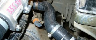
To monitor the coolant temperature, a sensor is screwed into the engine cylinder head, connected to the temperature indicator in the instrument cluster.
In the outlet pipe, next to the thermostat housing, there is a coolant temperature sensor that provides information to the controller.
The coolant pump is a vane, centrifugal type, driven from the crankshaft pulley by a timing belt.
The pump housing is aluminum.
The roller rotates in a double-row bearing. The bearing is lubricated for its entire service life.
The outer ring of the bearing is locked with a screw. A toothed pulley is pressed onto the front end of the roller, and an impeller is pressed onto the rear end.
A thrust ring made of a graphite-containing composition is pressed to the end of the impeller, behind which there is an oil seal.
The pump housing has a control hole to detect fluid leakage when the pump fails.
It is recommended to replace the pump as an assembly.
The redistribution of liquid flows is controlled by a thermostat.
The thermostat has a solid temperature-sensitive element and two valves that redistribute the flow of coolant.
On a cold engine, the main thermostat valve blocks the flow of fluid from the radiator, and the fluid circulates only in a small circle, bypassing the radiator.
At a temperature of (85±2) °C, the thermostat valves begin to move, allowing liquid flow into the radiator and closing the bypass channel.
At a temperature of about (100±2) °C, the main valve opens completely and the bypass valve closes.
Almost all the fluid circulates in a large circle through the engine radiator.
You can see the replacement of the thermostat in the article - “Removing and checking the thermostat.”
Coolant is poured into the system through the expansion tank. It is made of translucent polyethylene, which allows you to visually monitor the liquid level. To do this, the marks “MAX” and “MIN” are marked on the wall of the tank.
In the upper part of the tank there is a pipe for connecting to the radiator steam hose, in the lower part there is a pipe for connecting to the inlet hose.
The radiator consists of two vertical plastic tanks (the left one with a baffle) and two horizontal rows of round aluminum tubes passing through the cooling plates.
The tubes are connected to the tanks through a rubber gasket. The liquid is supplied through the upper pipe and discharged through the lower. Next to the inlet pipe there is a thin pipe for the steam removal hose.
The radiator has a casing with an electric fan. There is a drain plug at the bottom of the right tank.
The use of water in the cooling system is not recommended: hot water causes intense corrosion of aluminum parts.
Possible malfunctions of the engine cooling system and solutions
- The engine gets very hot
- Low coolant level in the expansion tank – Add coolant
- Thermostat is faulty (valve stuck in closed position) – Replace thermostat
- Water pump is faulty – Check the pump and replace if faulty
- The radiator core is clogged with dirt and insects – Wash the outside of the radiator core
- Radiator pipes, hoses and engine cooling jacket are clogged with scale and silt deposits – Flush the cooling system and fill with fresh coolant
- The electric fan does not turn on due to an open circuit of the sensor, failure of the sensor, relay or fan motor - Check and restore the electrical circuits. If necessary, replace the sensor, relay or electric fan assembly
- Damage to the valve in the expansion tank plug (constantly open, due to which the system is under atmospheric pressure) - Replace the expansion tank plug
- The engine overheats, cold air comes from the heater
- Excessively low coolant level due to a leak or damaged cylinder head gasket causing vapor lock in the engine water jacket – Repair the coolant leak. Replace damaged cylinder head gasket
- The engine does not warm up to operating temperature for a long time, the thermal regime is unstable while driving
- The thermostat is faulty (the valve is stuck in the open position) - Replace the thermostat (see article - “Replacing and checking the thermostat”)
- Constant decrease in coolant level in the expansion tank
- Radiator leaking - Replace radiator
- Expansion tank leaking - Replace expansion tank
- Coolant leaks through leaky connections of pipes and hoses - Tighten the hose clamps
- Water pump seal damaged - Replace water pump
- The sealing gasket of the water pump housing is damaged - Replace the sealing gasket
- The cylinder head mounting bolts are not tightened sufficiently (during long-term parking on a cold engine, a coolant leak appears at the junction between the cylinder head and the cylinder block; in addition, traces of coolant may appear in the engine oil) – Tighten the cylinder head mounting bolts to the required torque
- Heater core leaking - Replace heater core.
LiveInternetLiveInternet
—Categories
- Psychology (1)
- children (748)
- men (28)
- socks (141)
- ANIMATION (74)
- astrology, calendars (28)
- Pregnant (29)
- beads (47)
- our little brothers (21)
- bouquet of sweets (95)
- felting (14)
- everything made of paper (172)
- everything from traffic jams (7)
- KNITTING (412)
- Fortune Telling (19)
- getting ready for the holiday (207)
- AQUAGRIME (7)
- Design ideas. (67)
- interesting and beautiful (15)
- carving (15)
- computer, useful programs (83)
- suits (49)
- beauty and health (383)
- kitchen (71)
- LifeHack (14)
- Master Class (85)
- DIY FURNITURE (117)
- music (12)
- Soap making (25)
- soft toy (90)
- NEW LIFE TO OLD THINGS (90)
- tutorials (142)
- diary design (3)
- very good skillful hands (182)
- gifts (84)
- CUSHIONS (65)
- help (10)
- Parables, aphorisms (2)
- hairstyles (92)
- REPAIR WITH YOUR HANDS (23)
- RECIPES (468)
- Baking (79)
- winter preparations (95)
- salads, canapés, sandwiches (131)
- draw (81)
- HANDCRAFTS (206)
- garden design and just a summer house (243)
- wedding (23)
- Tips for housewives (156)
- cakes (147)
- Stencils (60)
- patterns (37)
- photoshop (45)
- cold porcelain, modeling (134)
- flowers (49)
- SEWING (230)
- curtains (17)
- humor (11)
-Music
—Search by diary
—Subscription by e-mail
-Statistics
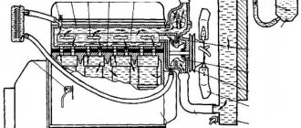
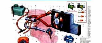
Design of the VAZ 2110, VAZ 2112 engine cooling system
Diagram of the VAZ 2110 engine cooling system (carburetor)
1 – heater radiator; 2 – steam removal hose of the heater radiator; 3 – outlet hose; 4 – supply hose; 5 – coolant temperature sensor (in the block head); 6 – pump supply pipe hose; 7 – thermostat; 8 – filling hose; 9 – expansion tank plug; 10 – coolant level indicator sensor; 11 – expansion tank; 12 – exhaust pipe; 13 – liquid chamber of the carburetor starting device; 14 – radiator outlet hose; 15 – radiator supply hose; 16 – radiator steam outlet hose; 17 – left radiator tank; 18 – sensor for turning on the electric fan; 19 – fan electric motor; 20 – electric fan impeller; 21 – right radiator tank; 22 – drain plug; 23 – electric fan casing; 24 – timing belt; 25 – coolant pump impeller; 26 – supply pipe of the coolant pump; 27 – supply hose to the liquid chamber of the carburetor starter 28 – discharge hose.
Scheme of the VAZ 2111, 2112 engine cooling system (injector)
1–26 – see above; 27 – coolant supply hose to the throttle pipe; 28 – coolant drain hose from the throttle pipe; 29 – coolant temperature sensor in the outlet pipe; 30 – radiator tubes; 31 – radiator core.
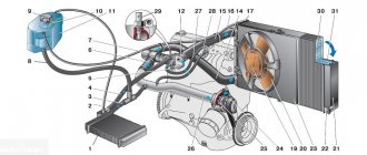
Scheme of the VAZ 21114, 21124 engine cooling system
The cooling systems of the VAZ-21114 and VAZ-21124 engines differ from the cooling systems of the VAZ-2111 and VAZ-2112 engines in the modified connection diagram of the heater radiator hoses, the installation of a new thermostat in a cast aluminum housing and an oversized expansion tank. The coolant level indicator sensor is not installed in the expansion tank. 1 – expansion tank; 2 – radiator outlet hose; 3 – radiator; 4 – radiator steam outlet hose; 5 – radiator supply hose; 6 – casing of the electric fan of the cooling system; 7 – thermostat housing; 8 – engine management system coolant temperature sensor (installed in the exhaust pipe); 9 – outlet pipe; 10 – coolant temperature sensor for the instrument cluster (installed in the cylinder head); 11 – cylinder head; 12 – throttle unit; 13 – bracket for fastening the supply pipe of the coolant pump; 14 – coolant pump; 15 – supply pipe of the coolant pump; 16 – heater radiator supply hose; 17 – heater radiator outlet hose; 18 – steam removal hose of the heater radiator; 19 – coolant pump supply pipe hose; 20 – filling hose.
Cooling system diagram
All the main elements are described below.
1 – heater radiator; 2 – steam removal hose of the heater radiator; 3 – outlet hose; 4 – supply hose; 5 – coolant temperature sensor (in the block head); 6 – pump supply pipe hose; 7 – thermostat; 8 – filling hose; 9 – expansion tank plug; 10 – coolant level indicator sensor; 11 – expansion tank; 12 – exhaust pipe; 13 – liquid chamber of the carburetor starting device; 14 – radiator outlet hose; 15 – radiator supply hose; 16 – radiator steam outlet hose; 17 – left radiator tank; 18 – sensor for turning on the electric fan; 19 – fan electric motor; 20 – electric fan impeller; 21 – right radiator tank; 22 – drain plug; 23 – electric fan casing; 24 – timing belt; 25 – coolant pump impeller; 26 – supply pipe of the coolant pump; 27 – coolant supply hose to the throttle pipe; 28 – coolant drain hose from the throttle pipe; 29 – coolant temperature sensor in the outlet pipe; 30 – radiator tubes; 31 – radiator core.
Cooling system components
Now that you know the entire diagram of the VAZ-2112 cooling system, you should learn about all its main details in more detail:
Cooling radiator
Copper cooling radiator
The radiator is designed to cool the fluid in the system as it passes through it in the so-called “great circle” . It is made of aluminum, has a tubular-plate, two-pass design, and is equipped with plastic tanks, one of which has a special partition designed to allow coolant to pass through. The liquid to pass through the “large circle” flows through the upper pipe and exits through the lower one.
Expansion tank
This tank is quite reliable, but its connections sometimes have to be checked for leaks.
The expansion tank, made of translucent polyethylene, is designed to fill and control coolant. When the fluid in the system is completely filled, it should be in the tank between o and “MAX”. Two pipes for removing steam are built into the tank, one from the heater radiator, the other from the cooling radiator.
Expansion tank cap
Two types of expansion tank caps.
The tightness of the cooling system is ensured by the expansion tank cap, or rather by its inlet and outlet valves. The exhaust valve maintains increased pressure on a hot engine compared to atmospheric pressure, due to which the boiling point becomes higher, reducing the loss of steam.
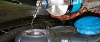
Procedure for draining antifreeze
To drain the antifreeze, it is necessary to ensure that the car is positioned in such a way that it stands level or the front part is higher than the rear.
Using keys, unscrew the ignition module to open the drain plug. The bracket may prevent this, so it is also advisable to dismantle it (this step is required only for injection machines).
Using a 13mm wrench and a ratchet, remove the drain cover of the cylinder block. As a result, a certain amount of liquid flows out of it. To collect it, you first need to place a container - it can be a bucket, a cut canister or any other container.
To speed up the process of draining the antifreeze, you can unscrew the cap of the expansion tank.
The last place to drain the fluid is the radiator. Its plug unscrews without much effort. Near the radiator drain hole there is a large number of wires and a generator. If possible, they should be protected from moisture, for example, by throwing a rubber cloth over them.
After removing the refrigerant, you need to wipe all the covers with a rag and tighten them, install the ignition module and bracket in place.
Tuning and repair of VAZ 2110
Since VAZ 2110 engines come in two types: injection and carburetor, the cooling systems are individual for them. Here we will look at both.
This cooling system consists of:
- Radiator for the stove.
- Heater radiator hose (steam removal)
- A pipe from the heater radiator to drain antifreeze.
- The pipe supplying antifreeze to the heater.
- Coolant temperature sensor (DTOZH)
- Pipe for supplying the pump pipe (water).
- Thermostat.
- Filling pipe
- Expansion barrel plugs
- A sensor indicating the coolant level.
- Expansion tank.
- Outlet hose.
- Exhaust manifold liquid heating chambers.
- Outlet pipe (from the radiator).
- Pipe for supplying fluid to the radiator.
- Steam exhaust pipe (from the radiator).
- Left radiator tank.
- Sensor for turning on the electric fan.
- Cooling fan drive electric motor.
- Fan impellers.
- Right radiator barrel.
- Radiator coolant drain plugs.
- Electric fan housings.
- Timing belt.
- Cooling pump impellers.
- Inlet pipe (to the water pump)
- Antifreeze supply hose to the liquid chamber of the carburetor starter.
- Outlet pipe.
Characteristics of DTOZH
First, let's look at the main characteristics of the regulator, which is often called a fan switch sensor. Let's start with the operating principle.
Principle of operation
The design of the part is based on a thermistor-resistor, which changes the resistance level depending on the temperature conditions. The thermistor itself is installed in a steel case with a thread applied to it. Directly connected to the body is the rear plastic part of the device, which contains the contacts necessary for connecting the power wires. One of these contacts is positive and it comes from the ECU, the second is negative, which is connected to the body.
In order for the engine temperature sensor to operate, it is powered by a voltage of 5 volts. The voltage is supplied from the ECU through a constant resistance resistor. Since the DTOZh thermistor itself has a negative temperature coefficient, as the temperature increases, the resistance parameter on it will begin to fall. In addition, the voltage supplied to it will also decrease. As a result of the decrease, the ECU calculates the temperature of the power unit, and the corresponding readings are transmitted to the instrument panel. The regulator should turn on when the ignition is turned on.
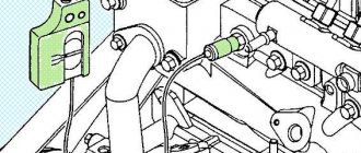
Where is?
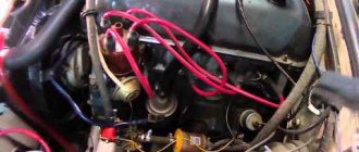
If you are the owner of a VAZ 21124, you will probably be interested in knowing where the coolant temperature regulator is located on a VAZ. On Ladas of the 12th family, the location of this device is quite simple - as can be seen from the photo, it is installed in the metal exhaust line of the cooling system on the cylinder head. The VAZ fan switch located here allows you to accurately determine the temperature of the consumable, since antifreeze passes through this line.
Cooling system for injection engines.
Points 1 to 26 are the same for the cooling system of carburetor engines.
Unlike the system described above, this system also consists of:
- The pipe supplying antifreeze to the throttle pipe.
- A pipe that drains fluid to the throttle pipe.
- DTOZH.
- Inside the radiator tube.
- Radiator cores.
System leakage
An even more popular problem among motorists is lack of pressure. This may happen due to:
- stuck air valve;
- presence of leaks in the cooling system.
Accordingly, identifying the problem will not be difficult. The first thing you can do is look at the antifreeze level on a cold engine. If it does not change from trip to trip, then there are no leaks in the system. The second step is to replace the air valve with a new one. After this, the pressure should normalize and the antifreeze will not overheat. Very often, increased pressure in the engine cooling system causes it to then drop. This is partly due to the wedging valve. Sometimes it works, sometimes it doesn't. As a result, pressure builds up, which can cause a leak to form in a weak spot, and then the seal disappears.
Features of the VAZ 2110 cooling system
Engine cooling type is liquid, closed, forced circulation. The system operates under excess pressure, the nominal heating is 87-94 C. The system is sealed, the expansion tank is closed with a lid with two valves: outlet and inlet. The intake valve opens at a pressure of 0.035-0.135 kgf/cm2, this happens when the engine cools down in order to suck in the required volume of air. And the outlet is activated at a pressure of 1.05-1.55 kgf/cm2, in order to relieve excess pressure.
Maintaining the optimal engine temperature is made possible thanks to an electric fan and thermostat. The first one is set in motion when the contacts on the thermal switch (located in the radiator tank) close. Contacts close at a temperature of 99-101 C, and open at 92-94 C.
In a VAZ 2110 car, the electric fan is switched on automatically simultaneously with the sensor signal that the antifreeze temperature has been exceeded.
The rotation of the fan wheel is carried out by a DC commutator motor.
The antifreeze temperature is determined by a sensor. It is located in the cylinder block. If your engine has electronic injection, then you may find another sensor in the engine head. It transmits information to the electronic control unit about the degree of heating.
The liquid circulates through the system thanks to a conventional centrifugal pump called a pump. Its rotation occurs due to the operation of the engine (via a belt).
Pump mechanism: Inside the aluminum housing there is a shaft, which ends at one end with a toothed pulley, and at the other end with an impeller.
Cooling of the VAZ 2110 engine can occur in a small and large circle. If the antifreeze temperature is lower than the set temperature, then the thermostat (the mechanism responsible for distributing the coolant) shuts off the flow of liquid into the radiator with a valve. In this case, cooling in a small circle. When the liquid temperature reaches 86-88 C, the thermostat opens the path of liquid through the main pipe. At this point, most of the antifreeze passes through the radiator. When the liquid temperature exceeds 101 C, the pump valve opens completely and in this case all the liquid passes through the radiator, which in turn is cooled by the fan.
Coolant is poured into the reservoir under the hood. It contains divisions of the minimum and maximum levels. In addition, a level sensor is built into the tank, which will inform you through a light on the instrument panel about the lack of antifreeze.
Why did the car manufacturer come up with a steam pipe here? Everything is simple, for removing steam from the heater radiators and cooling into the expansion tank. Thanks to this thing, steam locks will not appear in the system, since all the steam will escape through the valve of the expansion tank cap.
It is strictly forbidden to use water as a coolant for the VAZ 2110 engine, since the first thing is corrosion will begin, and the second thing is that hot water tends to corrode aluminum parts.
And the last thing I want to talk about about the device in this article is the radiator. Its structure: core, two plastic tanks. The left one is divided inside by a partition. The core is aluminum tubes with plates on them, also made of aluminum.
How to remove an air lock from the cooling system of a VAZ 2112
If the new fluid was added incorrectly, the cooling system will not work correctly.
To eliminate airiness, squeeze the pipe from which excess air comes out. After this, it is necessary to increase the pressure in the expansion tank. When antifreeze begins to come out of the return line, then the procedure can be stopped.
After this, you need to tighten the plug and put on the terminals. During the first start, keep the engine speed high, this will also help stimulate the release of excess air.
Checking the correct filling of antifreeze is carried out as follows: as the engine warms up, the radiator cooling fan should turn on. If the stove next to the fan starts to heat up, it means the work was done correctly.
If the system does not heat up, it is necessary to check the tightness - perhaps a leak has formed somewhere. If there is no leakage, then the air has not completely escaped.