Why is a crankshaft needed in a VAZ 2106 engine?
The crankshaft (crankshaft) is an important part of the crank mechanism of any engine. The operation of the unit is aimed at converting the energy of combustion gases into mechanical energy.
Description of the VAZ 2106 crankshaft
The crankshaft has a rather complex design, with connecting rod journals located on the same axis, which are connected through special cheeks. The number of connecting rod journals on the VAZ 2106 engine is four, which corresponds to the number of cylinders. Connecting rods provide connection between the journals on the shaft and the pistons, resulting in reciprocating movements.
Let's look at the main elements of the crankshaft:
- Main journals are the supporting part of the shaft and are installed on main bearings (located in the engine crankcase).
- Crankpins. This part is designed to connect the crankshaft to the connecting rods. The connecting rod journals, unlike the main ones, have a constant displacement to the sides.
- Cheeks are a part that provides connection between two types of shaft journals.
- Counterweights are an element that balances the weight of connecting rods and pistons.
- The front part of the shaft is the part on which the pulley and timing gear are mounted.
- Rear end. The flywheel is attached to it.
Seals are installed in front and behind the crankshaft - oil seals, which prevent oil from escaping out. The entire crankshaft mechanism rotates thanks to special plain bearings (liners). This part is a thin steel plate that is coated with a low-friction material. To prevent the shaft from moving along the axis, a thrust bearing is used. The material used in the manufacture of the crankshaft is carbon or alloy steel, as well as modified cast iron, and the production process itself is carried out by casting or stamping.
The crankshaft of the power unit has a complex structure, but the principle of its operation is quite simple. In the engine cylinders, the fuel-air mixture ignites and burns, resulting in the release of gases. During expansion, the gases exert an impact on the pistons, which leads to translational movements. Mechanical energy from the piston elements is transferred to the connecting rods, which are connected to them through the bushing and piston pin.
An element such as a connecting rod is connected to the crankshaft journal using a liner. As a result, the translational movement of the piston is converted into rotation of the crankshaft. When the shaft makes a half revolution (turns 180˚), the connecting rod journal moves back, thereby ensuring the return of the piston. Subsequently, the cycles are repeated.
No less important in the operation of the crankshaft is the process of lubrication of rubbing surfaces, which include the connecting rod and main journals. It is important to know and remember that lubricant is supplied to the shaft under pressure created by the oil pump. Oil is supplied to each main journal separately from the general lubrication system. Lubricant is supplied to the connecting rod journals through special channels located in the main journals.
Neck sizes
The main and connecting rod journals wear out as the engine operates, which leads to disruption of the proper operation of the power unit. In addition, wear can be associated with various types of engine problems. These include:
- low pressure in the lubrication system;
- low oil level in the crankcase;
- overheating of the engine, which leads to oil dilution;
- low quality lubricant;
- severely clogged oil filter.
The listed nuances lead to damage to the surface of the shaft journals, which indicates the need for repair or replacement of the unit. To assess the wear of the journals, you need to know their dimensions, which are shown in the table.
Table: crankshaft journal diameters
| Connecting rod | Indigenous | ||||||||
| Nominal | Repair | Nominal | Repair | ||||||
| 0,25 | 0,5 | 0,75 | 1 | 0,25 | 0,5 | 0,75 | 1 | ||
| 47,814 | 47,564 | 47,314 | 47,064 | 46,814 | 50,775 | 50,525 | 50,275 | 50,025 | 49,775 |
| 47,834 | 47,584 | 47,334 | 47,084 | 46,834 | 50,795 | 50,545 | 50,295 | 50,045 | 49,795 |
What to do when necks wear out
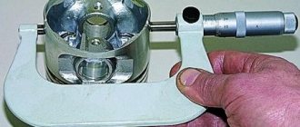
What are the steps to take if the crankshaft journals are worn out on a VAZ 2106? First, the defectiveness is carried out, measurements are taken using a micrometer, after which the crankshaft journals are polished using special equipment to the repair size. This procedure cannot be done in a garage environment. The necks are ground to the closest size (based on the tables provided). After processing, thickened liners (repair) are installed in accordance with the new size of the necks.
If a major overhaul of the engine is being carried out, it would not be superfluous to inspect the oil pump, blow out the oil passages of the cylinder block, as well as the crankshaft itself. Attention should be paid to the cooling system. If there are signs of wear or damage on the engine elements or its systems, the parts and mechanisms need to be repaired or replaced.
Video: grinding the crankshaft on a machine
Crankshaft selection
The need to select a crankshaft for a VAZ 2106, like for any other car, arises in case of engine repair or to improve engine performance. Regardless of the task at hand, it must be remembered that the crankshaft must be heavy, with large counterweights. If the part is selected correctly, mechanical losses will be significantly reduced, as well as other loads on the mechanisms.
In the process of selecting a unit, even if it is new, close attention is paid to its surface: there should be no visible flaws, such as scratches, chips, or burrs. In addition, attention is paid to a number of crankshaft characteristics, namely coaxiality, ovality, taper and journal diameter. During engine assembly, the crankshaft is balanced to balance all rotating elements. A special stand is used for this procedure. Once balancing is completed, secure the flywheel and continue the process again. Afterwards, the clutch basket and other elements (pulleys) are mounted. There is no need for balancing with the clutch driven disc.
Piston pin VAZ 21213, 2101-07, 2121, 2123 (blue, green, red)
Dear customers, in order to avoid mistakes when sending a set of piston pins, in the “Comment” line indicate the model and year of manufacture of your car, the class of the piston pin (blue color - 1st class, green color - 2nd class, red color - 3rd class th class).
The clouds of bluish smoke escaping from the exhaust pipe give the driver many unpleasant thoughts. This most often indicates an unpleasant, but inevitable moment in the life of a car - engine repair.
When the car has traveled approximately 150 thousand kilometers, noticeable wear of the piston group occurs.
The connecting rod and piston group - connecting rod, piston with rings, connecting rod or main bearings - is the most important component in the engine. If the technical condition of these elements in the engine is inappropriate, the following is observed: reduced compression, possibility of jamming
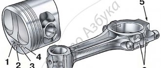
The piston pin is designed to articulate the piston with the upper head of the connecting rod. It is made hollow (in the form of a thick-walled tube). In order for the fingers to work reliably when transmitting large forces, they are made of steel (alloy or carbon). The pin is secured in the piston bore by two spring retaining rings.
By diameter, piston pins are divided into three classes at 0.004 mm intervals.
The class of the piston pin is marked with paint on its end:
blue color - 1st class
green color - 2nd grade
red - 3rd grade
The piston is cast aluminum. During manufacturing, the weight of the pistons is strictly maintained.
The piston rings are made of cast iron. The upper compression ring has a chrome-plated barrel-shaped outer surface. The lower compression ring is scraper type. The oil scraper ring has chrome-plated working edges and an expansion coil spring.
Connecting rod – steel, forged. The connecting rod is processed together with the cover and therefore they are individually non-interchangeable. To avoid mixing up the caps and connecting rods during assembly, they are marked with the number of the cylinder in which they are installed. A steel-bronze bushing is pressed into the upper head of the connecting rod. Based on the diameter of the hole in this bushing, the connecting rods are divided into three classes every 0.004 mm (the same as the pistons). The class 5 number is stamped on the connecting rod cover.
The design of the VAZ 21213 piston uses a free fit of the piston pin. The clearance in the hole in the connecting rod head and in the holes in the piston ensures free rotation of the pin. The pin is secured in the axial direction with locking rings. For this purpose, the piston, in the pin holes, has installation grooves for retaining rings. On the outside of the piston pin holes, in the upper part, there are small recesses that make it easier to install and remove the circlips. In addition, they facilitate the access of oil to the contact area.
This design simplifies the assembly process and ensures uniform wear of rubbing surfaces, increasing the service life of parts.
Rice. 1. Main dimensions of the connecting rod and piston group of VAZ 21213
The piston and its corresponding cylinder must belong to the same class, just as the piston and piston pin must belong to the same category.
Based on the diameter of the hole for the piston pin, pistons are also divided into three classes every 0.004 mm.
Crankshaft pulley
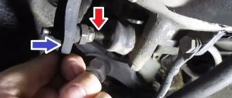
The generator and water pump on the VAZ 2106 are driven by a belt from the crankshaft pulley. When carrying out repair work on the engine, attention should also be paid to the condition of the pulley: is there any visible damage (cracks, scuffs, dents). If defects are found, the part should be replaced.
During the installation process, the pulley should sit smoothly on the crankshaft, without distortion. Despite the fact that the pulley fits quite tightly on the shaft, a key is used to prevent rotation, which can also be damaged. A defective part must be replaced.
Crankshaft marks
In order for the engine to work flawlessly, after installing the crankshaft, the correct ignition setting is necessary. There is a special casting on the crankshaft pulley, and on the cylinder block there are three marks (two short and one long) corresponding to the ignition timing. The first two indicate an angle of 5˚ and 10˚, and the long one - 0˚ (TDC).
The mark on the crankshaft pulley is located opposite the length of the marks on the cylinder block. There is also a mark on the camshaft sprocket that must be aligned with the casting on the bearing housing. To rotate the crankshaft, use a special wrench of the appropriate size. According to the marked marks, the piston of the first cylinder is at top dead center, while the slider on the ignition distributor must be installed opposite the contact of the first cylinder.
Despite the fact that the crankshaft is a critical component of any engine, even a novice auto mechanic can repair the mechanism, with the exception of the grinding stage. The main thing is to select the elements according to the dimensions of the shaft, and then follow the step-by-step instructions for assembling it.
We remove the crankshaft to replace it or replace the bearings.
Connecting rod VAZ 2101 dimensions
This article contains some information about the modification of classic VAZ engines. There are a lot of different articles floating around the Internet, here, so to speak, a little from everywhere, and from myself, of course.
Information on the sizes of VAZ classic engines:
The height of the cylinder block for a classic VAZ car (from the crankshaft axis to the plane of the cylinder head gasket): - 2101, 21011, 2105 = 207.1 tolerance -0.15, - 2103, 2106, 2121, 2130 (1.8 liters) = 215.9 tolerance -0.15, - 21213 (on motor 21214 block 21213) = 214.58 tolerance -0.15.
The thickness of the cylinder walls usually allows the diameter to be increased by no more than 3 mm; if the water jacket, or rather the diameter of the cylinder, is shifted relative to the jacket, problems may arise. The casting leaves much to be desired.
We also do not forget that for some classic blocks, such as 2103/2106, the piston undershoot ranges from 1.9 to 2.3 mm. 2101/212123 has from 0 to 0.7. Those. the blocks were cast at random.
I would advise reducing this shortfall in 03/06, if possible, by milling the plane of the block. Of course, unless we are talking about a different crankshaft, when the ratio of cylinder volume to combustion chamber changes. After all, the compression ratio of classic engines is only 8.6-8.8 units. After reducing the income loss to 0.9mm, the lifespan is obtained
9.5-9.8 units For a block with a small income loss, the coolant can be increased only by milling the cylinder head.
Those. block milling, etc. By the way, like the cylinder head plane, it increases the coolant by about 1mm!, mind you, exactly by about 1 unit. More accurately, you need to pour it with a syringe and count using a calculator. The resulting coolant is quite acceptable for civilian use on 92 gasoline.
A subsequent increase in coolant is possible by milling the cylinder head plane. You can shoot down to 3mm! At least I’ve read about such actions many times - and everything drives fine. Naturally, this will entail a transition to high-octane gasoline of at least 95, or even 98, in the case of severe milling.
Knee stroke 2101, 2103, 21213: stroke 2101 - 66mm (commonly called low) stroke 2103 - 80mm stroke 21213 - 80mm (more balanced due to more developed counterweights, apparently to the detriment of weight) stroke 2130 - 84mm
There are tuner elbows with a stroke of 84,86,88 mm. But they cost from 10 thousand.
Piston diameter for classics: 2101 - 76mm (76.4/76.8) 21011/2105 - 79mm (79.4/79.8) (have puddles 2mm deep and
10cm2) 21213/2108 - 82mm (82.4/82.8)
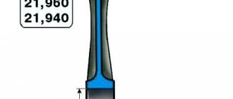
There are many cast and forged pistons available in any diameter from stock to 84mm. One of the main geometric characteristics of the piston is compression height. It is determined by the distance from its bottom to the piston pin axis. For a classic VAZ engine it is 38 mm. There are pistons with a lower compression height, such as TPT pistons. The height is 31 mm.
Installation
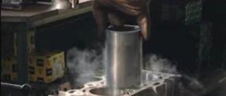
1. Wash the crankshaft in kerosene and blow through its internal cavities with compressed air. We install new crankshaft main bearing shells of nominal or repair size. On the outer cylindrical surface of the liners there are numbers stamped indicating the repair size: 025 - the first repair, for the crankshaft journal, reduced in diameter by 0.25 mm. Accordingly, for the second, third and fourth repair sizes the values will be: 050, 075, 100. It is easy to distinguish connecting rod bearings from main bearings. The upper main bearings (except for the middle one) have annular grooves. In addition, the middle support liners are wider than the others. The connecting rod bearings are all identical and interchangeable, their diameter is less than the diameter of the main bearings. To increase the contact area, there are no annular grooves on the connecting rod bearings.
2. We install thrust half-rings in the grooves of the fifth main bearing with grooves towards the crankshaft. Half rings are manufactured in normal thickness (2.310-2.360 mm) and increased thickness (2.437-2.487 mm).
3. We check the axial clearance between the thrust half-rings and the thrust surfaces of the crankshaft, which should be in the range of 0.06-0.26 mm. If the gap exceeds the maximum permissible (0.35 mm), replace the thrust half-rings with new ones, increased by 0.127 mm.
4. Lubricate the connecting rod and main journals of the crankshaft with engine oil and install the shaft into the block.
5. In accordance with the marks, install the main bearing caps and tighten their mounting bolts to a torque of 68.4-84.3 Nm. Check the free rotation of the shaft.
6. Install connecting rods with liners and covers on the crankshaft. Tighten the fastening nuts to a torque of 43.4-53.5 Nm.
8. Install the holder with the oil seal on the cylinder block (see “Crankshaft rear oil seal - replacement”).
9. Installation of the remaining removed parts is carried out in reverse order.
12. On a carburetor engine, we check and, if necessary, adjust the ignition timing (see “Ignition timing - checking and adjustment”).
Checking the condition and selecting the main and connecting rod bearings of the crankshaft
Despite the fact that the crankshaft bearings must be replaced during engine overhaul, the old bearings should be retained in order to carefully study their condition, the results of which can provide a lot of useful information about the general condition of the engine. The illustration shows examples of typical defects in bearing shells. Bearing failure can occur due to lack of lubrication, ingress of dirt particles, engine overload and the development of corrosion. Regardless of the nature of the defects, the cause of damage to the liners must be eliminated during the engine overhaul in order to avoid relapse.
For inspection, remove the bearing shells from their housings in the engine block/lower connecting rod ends and main/connecting rod caps and place them in the order of installation on a clean work surface. The organization of the placement of the liners will make it possible to link the nature of the identified defects to the condition of the corresponding shaft journals.
Dirt and foreign particles enter the engine in various ways. They can be left inside the unit during assembly of the unit, or penetrate through filters or the crankcase ventilation system. All particles that enter the engine oil eventually, sooner or later, end up in the bearings. Often, metal filings are embedded in the soft material of the liners, which are formed during the normal operation of internal engine components. There is a high probability of traces of abrasive being present in the bearings, especially when due attention has not been paid to cleaning the block after completing the engine rebuild. Regardless of the method in which foreign particles enter the engine, as a result they are highly likely to be embedded in the soft surface of the crankshaft bearing shells and are easily identified during visual inspection of the latter. Large particles usually do not linger in the liners, but leave noticeable marks on their surface and the surface of the shaft journals in the form of scratches, cavities and burrs. The best guarantee against this kind of trouble is a responsible attitude to cleaning components after completing an engine overhaul and careful attention to cleanliness during assembly. Frequent, regular changes of engine oil can also significantly extend bearing life.
Pistons - replacement
To complete the work, you will need mandrels to remove the piston pin and compress the rings.
1. Place the car on an inspection hole or overpass (see “Preparing the car for maintenance and repair”).
2. Remove the cylinder head from the engine (see “Cylinder head gasket - replacement”).
3. Remove the engine sump (see “Engine sump - removal and installation”).
4. Unscrew the nuts of the connecting rod caps (without removing the crankshaft) and push the piston and connecting rod out of the cylinder block (see “Crankshaft - removal and installation”).
5. Remove the steel-aluminum liner from the connecting rod cover.
The connecting rod and cap are stamped with the number of the cylinder in which they are installed.
6. Place the connecting rod in a vice and remove two compression rings and one oil scraper ring with an expander from the piston.
7. Press the pin out of the connecting rod through the mandrel and remove the piston.
Similarly, remove the pistons of the remaining cylinders.
Before installing the piston group on the connecting rod, it is necessary to select its parts.
Selection of connecting rod and piston parts
1. Select the piston to the cylinder. The calculated gap between the cylinder and the engine piston should be 0.06-0.08 mm. It is determined by measuring the cylinders and pistons and is ensured by installing pistons of the same class as the cylinders. The maximum permissible gap is 0.15 mm. The piston diameter is measured in a plane perpendicular to the piston pin, at a distance of 52.4 mm from the piston bottom. The outer diameter of the pistons is made into five classes (A, B, C, D and E) every 0.01 mm, and the diameter of the hole for the piston pin is made into three categories every 0.004 mm. Spare parts include pistons of groups A, C and E. The piston class (letter) and the category of the piston pin hole (number) are stamped on the piston bottom.
For correct orientation of the piston relative to the cylinder, there is a “P” mark on the piston wall (next to the boss), which should be directed towards the front of the cylinder block.
Connecting rod main and crankshaft journals VAZ 2107, VAZ 2105, VAZ 2104, Lada Zhiguli, Classic
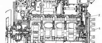
The device of the crankshaft and flywheel of VAZ 2107, VAZ 2105, VAZ 2104
Crankshaft and flywheel VAZ 2107, VAZ 2105, VAZ 2104
Permissible runout of the main surfaces of the crankshaft
Examination. Install the crankshaft of the Lada classic on two prisms and check with an indicator:
- runout of the main journals (maximum permissible 0.03 mm); - runout of the seating surfaces under the sprocket and gearbox input shaft bearing; maximum permissible 0.04 mm;— displacement of the axes of the connecting rod journals from the plane passing through the axes of the connecting rod and main journals (maximum permissible ±0.35 mm);
— non-perpendicularity of the end surface of the flange with respect to the axis of the crankshaft. When turning the shaft, the indicator installed on the side, at a distance of 34 mm from the shaft axis, should not show a runout of more than 0.025 mm.
Cracks are not allowed on the main journals, connecting rod journals and on the crankshaft cheeks. If they are found, replace the shaft. Scratches, nicks and risks are not allowed on the surfaces of the crankshaft mating with the working edges of the oil seals.
Measure the diameters of the main and connecting rod journals. The journals should be ground if their wear is more than 0.03 mm or the ovality of the journals is more than 0.03 mm, and also if there are burrs and marks on the journals.
The main dimensions of the connecting rod and main journals of the crankshaft and their fillets
Grinding the journals of VAZ 2104. Grind the main and connecting rod journals of VAZ 2104, VAZ 2105, VAZ 2107, reducing by 0.25 mm so as to obtain, depending on the degree of wear, diameters corresponding to the values given in the table. and radii of neck fillets.
After grinding and subsequent finishing of the journals, rinse the crankshaft of the VAZ 2107 thoroughly to remove any remaining abrasive. Wash the lubrication channels with the plugs removed several times with gasoline under pressure. On the first cheek of the crankshaft, mark the amount of reduction of the main and connecting rod journals (for example, K 0.25; W 0.50). The ovality and taper of the main and connecting rod journals of the VAZ 2105 after grinding should be no more than 0.007 mm.
Maintenance of the Lada 2104 engine. Instructions for repairing the engine and systems: power, cooling and lubrication of the Lada 2105. Inspection and repair of the crankshaft and camshaft, piston group of the Lada 2107. Instructions for disassembling and assembling the cylinder head and block.,
Connecting rod main and crankshaft journals VAZ 2107, VAZ 2105, VAZ 2104
- Engine systems VAZ 2104, VAZ 2105, VAZ 2107,
- Engine repair VAZ 2107, VAZ 2105, VAZ 2104
- . Stages of do-it-yourself crankshaft repair Lada 2107, replacement of bearing shells on VAZ 2104, VAZ 2105, VAZ 2107 cars.. Main and connecting rod journals
www.VazClub.com