Signs, symptoms and causes of sensor failure in a car
Good day, dear readers! In the article we will analyze which sensors are responsible for what in diesel and gasoline engines, as well as characteristic signs of their incorrect operation. Remember that before you go to the service station and panic, you should spend a little time and try to find the cause of the malfunction yourself and fix it.
Signs of a malfunction of the TPS sensor
— high speeds are possible at idle, this is the most characteristic sign; — a noticeable decrease in engine power and deterioration in throttle response; — when you press the accelerator, jerks, dips and twitches appear; — floating speed at idle; — when changing gears, the engine stalls spontaneously; — engine overheating is possible; — when accelerating, detonation is observed.
(personally, my symptoms were high speeds, inability to brake with the engine, jerking when releasing the gas pedal, decreased power and, accordingly, increased gasoline consumption).
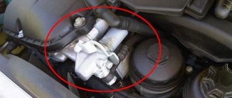
The photo shows very worn tracks
The reasons for the malfunction of the TPS sensor can be: - oxidation of the contacts, in this situation you need to take a special WD fluid and clean all the contacts in the block and under the cover with a lint-free cloth; — worn-out sensor substrates, if their design included sputtering of a resistive layer, in this situation we take tweezers and carefully, just a little bit, bend the contacts onto entire tracks; — the moving contact fails, some tip of this contact may break, then scoring will form and other tips will also fail; — the throttle valve does not close completely at idle, in this case you can slightly file the sensor seats and the throttle valve should close.
The speed sensor rarely fails
, the average car owner will not be able to diagnose the breakdown, some do not even know where the sensor itself is located, it is located opposite the throttle valve.
The check error does not always appear.
We recommend an article about repairing the TPS; it discusses one of the ways to restore its functionality.
Signs of a malfunctioning idle air valve
— unstable engine speed at idle; — spontaneous increase or decrease in engine speed; — the engine stalls when shifting gears or idling; — no increased speed when starting a cold engine; — reduction in engine idle speed when the load is turned on (headlights, stove, etc.).
The idle control valve will not be able to function normally in this state.
The check error does not always appear.
The best prevention is considered
periodic cleaning of the idle air valve with removal, usually done in the fall and spring. The valve is located near the throttle valve.
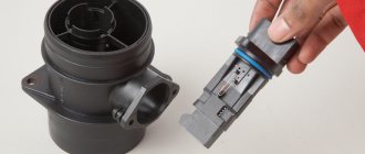
Signs of a malfunction of the mass air flow sensor
The MAF sensor can be called a mass air flow sensor, MAP or maf sensor.
Signs of a malfunction of the air flow sensor or absolute pressure in the intake manifold are characterized by: - up to 70 degrees the car works more or less well, after 70 an unstable idle begins; — failures during acceleration and adjustments; — the car sometimes stalls at idle when the gas pedal is sharply pressed; — increased consumption; — unpleasant exhaust smell; — popping noises in the muffler during operation and sometimes popping noises in the intake manifold. (incorrect ignition timing due to faulty sensor).
The air flow sensor is very sensitive and it is not recommended to clean it yourself; the more often you change the filter, the longer it will last you.
The check error only appears when the air flow sensor has stopped working completely, and it can give incorrect readings for a long time.
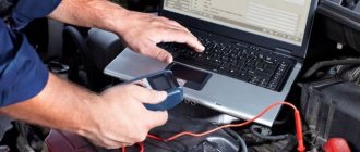
Check DMRV
or a mass air flow sensor, you can have a multimeter or diagnostic scanner on hand.
Signs of a malfunctioning speed sensor
— the speedometer does not work or gives incorrect readings; — unstable idling; — increased fuel consumption; - the engine stops developing full power. — the fuel gauge needle reacts almost instantly to fluctuations in the fuel level in the tank because the computer thinks that the car is not moving and “smoothes” the sensor readings less; — the odometer does not show mileage; — When changing speed, the automatic transmission resets itself to neutral, or switches spontaneously in an illogical manner; — the car stops responding to the gas pedal and coasts; — in city driving, when picking up speed, the box sharply increases speed and does not accelerate, does not react to other modes 2 and 1. It seems to only drive at speed 1 but does not slow down with the engine.
The principle of operation of the speed sensor on all cars is the same and you can restore it yourself
, let's look at the example of repairing a Nissan Cefiro speed sensor. The speed sensor is located, in most cases, on the automatic transmission side.
Signs and causes of a malfunctioning knock sensor
— It rarely fails. Before the sensor breaks, something is more likely to happen to its wiring. Perhaps something happened to them if, at speeds exceeding 3000, the engine’s sensitivity to how high-quality fuel is poured into it increases. If the fuel turns out to be of poor quality, finger knocking will occur.
knock sensor
- symptoms of incorrect ignition timing. Anyone who has driven a car with a manual engine control system knows what I'm talking about. If you only shift the OZ a few degrees to the early or late side, the engine will either lose its dynamics, as if you were driving with a handbrake, or it will begin to detonate—ringing at light loads or “shooting” into the exhaust system. Everything depends on the detonation resistance of the fuel poured in and the level of pressure at which your engine operates.
Symptoms of a bad timing sensor
A breakdown of the crankshaft sensor is manifested by:
— a noticeable decrease in engine power;
— “floating” engine speeds;
— detonation triggered in the engine during active movement;
- absence of signs of life in the sensor, when it is impossible to start the car.
The presence of such problems indicates the need to check the crankshaft position sensor.
Incorrect operation of the DPKV is manifested by:
- a noticeable deterioration in its dynamic characteristics when driving the car (the reasons for this problem may be different, but if the malfunction concerns the synchronization sensor, then “check engine” will appear on the instrument panel).
— spontaneous decrease or increase in speed;
— lack of stability in speed;
— the phenomenon of detonation in the engine accompanying dynamic load;
- inability to start the engine.
This is only an incomplete list of characteristic symptoms of crankshaft speed sensor malfunctions.
It is important to understand how you can check the functionality of a given unit in order to be absolutely sure that it is working properly. This check should always be carried out first, and here's why. Despite the rather inconvenient location of the crankshaft sensor in most cars, the process of checking it is relatively simple. But you will know for sure whether the sensor needs to be changed or not.
Crankshaft sensor malfunction
If you don’t know yet, then we’ll tell you a secret from the operating manual: a malfunction of the crankshaft sensor can lead to either the inability to start the car’s engine, or to a loss of power, a failure in speed, and ultimately, again, to stopping the engine.
The thing is that it is the crankshaft speed sensor that synchronizes the fuel supply and ignition timing by transmitting pulses to the ECU of your car.
Signs of a faulty crankshaft sensor
The first sign of engine malfunction, in general, is a noticeable decrease in its dynamics while driving. This could, of course, indicate any malfunction occurring in the engine. But, the controller will fix it and light up the “CHECK ENGINE” indicator on the dashboard.
Symptoms in engine operation such as:
- at idle the engine speed is unstable;
- the engine spontaneously decreases or increases speed;
- a noticeable, even without instruments, reduction in engine power;
- under dynamic load, detonation occurs in the engine;
- finally, the elementary inability to start the engine.
These are the most typical signs that the crankshaft speed sensor, timing pulley or generator is faulty.
First of all, let’s pay attention to the crankshaft position sensor, how to check it so that the test result accurately shows that it is the sensor that is faulty. Why is the crankshaft position sensor checked first?
It's simple. Although the timing sensor is usually located in an inconvenient place on the engine, diagnosing it will take the least of your time and resources. And the diagnostics will show whether the sensor is working or whether the crankshaft speed sensor needs to be replaced.
What is an engine speed sensor?
When certain problems arise with the power unit, motorists often ask questions: does it have a mechanism that would help determine the speed. Well, since the first suspicion in the event of malfunctions falls precisely on the engine speed, then it is the engine speed sensor that interests them. But it also happens that engine problems can be caused by completely different reasons. Therefore, it is appropriate to first determine the CC source of the malfunction and only then check the meters. But in any case, if you need to locate the desired sensor, you will need at least a little information about its location, features, and, in general, about basic concepts.
Types of automotive engine speed sensors
There are several types of automotive engine rotation meters based on the principle of creating and recording changes in a sensitive environment.
Induction (inductive)
Inductive engine speed synchronization sensors are the simplest, most common, and cheapest, but this does not reduce their effectiveness.
The main element of induction detectors of the number of rotations of internal combustion engines is a coil that magnetizes the core and creates magnetic fluxes.
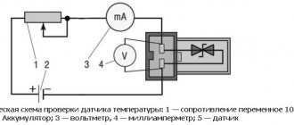
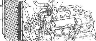
In the following explanation, digital links to the figure below. The inductive synchronization sensor is installed immediately opposite the gear ferromagnetic part of the HF (7). It also has a small air gap (the place where there are no protrusions). The sensor inside consists of a magnetized steel core (pole contact rod, 4), with a winding of thin copper, insulated enamel wire (5), similar to that of transformers. This element is connected to a permanent magnet (1).
- The pole contact pin spreads the magnetic field, which passes onto the gear shaft.
- The teeth touch the magnetic flux passing through the coil, its properties at the protrusions and depressions change. At first, this scattered flow becomes more concentrated (beam). On the second, on the contrary, this phenomenon is weakened.
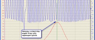
- The above transformations induce an output alternating voltage with a certain sinusoid on the turns of the winding. The value is proportional to the speed and number of revolutions (Fig. 2). The amplitude grows rapidly as they increase (from several mV to 100 V and more). A sufficient value is generated starting from a minimum number of rotations of 30/min.
Optical
The design consists of an IR LED with a receiver installed opposite it. Between the elements are the crankshaft teeth. The emission line is crossed by these protrusions, which detects the receiver and sends a corresponding pulse to the ECU. Used less frequently.
Active
Next, we will consider the so-called “active” motor rotation sensors, operating using the magnetostatic method. With them, the amplitude of the output pulse is not affected by the number of revolutions, so measurements of the intensity of HF turns become available with an extremely low number of them (quasi-static monitoring). Such products are much more advanced, with expanded capabilities.
Motor speed sensors with differential Hall detectors
On a conductive plate that transmits magnetic induction in the vertical direction, a so-called Hall voltage proportional to its direction can be recorded transverse to the current flow.
A diagram of this option is shown above. In such a DPKV differential sensor, the field is created by a permanent magnet (1). Two Hall sensors (2 and 3) are placed between the magnet and the pulse-producing ring (4). Changes occur in the magnetic flux depending on what appears on it - a depression or a tooth. The difference between the signals of the two sensors reduces disturbance and the level of deviations, and improves the signal-to-noise ratio. Side sections of the signal can be analyzed without digitization directly on the control unit.
Synchronization gears can be not only ferromagnetic, but also multi-pole, where a non-magnetic metal carrier is equipped with a piece of special plastic, which is alternately magnetized. The north and south poles of such an element act as divisions.
The sensitive part of the AMR vehicle speed synchronization sensors is made of a magnetoresistive compound.
AMP - anisotropic magnetoresistive. The first term means that the electrical resistance of this material depends on the direction of the acting magnetic field. Such a sensor is installed between a magnet and a pulse disk (analogous to a gear one, as with inductive sensors).
When the pulsed active disk rotates, the field lines change their parameters, which forms a sinusoidal voltage, amplified by the data processing circuit, which is converted into a pulse of rectangular geometry.
In this case, the innovative Giant Magneto-Resistance technology is used. This sensor is much more sensitive than AMR - significant air gaps are possible here.
GMR engine speed sensors are used for difficult conditions; high sensitivity creates less noise and signal errors.
Advanced GMR detectors are equipped with two-wire ports; they are also sometimes found in Hall rotation sensors.
What is a speed sensor and why is it needed?
A speed sensor is provided in the engine device to perform the function of synchronizing the ignition and fuel injection systems. This meter is often also called a speed meter. The speed sensor transmits the necessary information to the electrical unit, as well as data about what rotations the crankshaft supports at a particular moment. This meter is considered the most important mechanism of the car, since the interaction of most systems depends on it. It helps ensure the correct functioning of the entire vehicle. Special signals are processed by the ECU and sent to the meter in order to find out several important points. This is the amount of fuel injected at a given moment, the injection moment itself and the time to activate the canister valve, as well as the ignition timing and the camshaft rotation angle. Well, of course, to determine the malfunction and check the device, you first need to find it in the car.
Where is the speed sensor located?
The induction meter or rpm sensor is mainly located above the marker disc of the vehicle. In turn, this element can be located either on the flywheel, or on the crankshaft inside the cylinder block, or in front of the engine compartment on the crankshaft. Very often, a slight curvature of the flywheel teeth or the presence of a small chip can lead to malfunctions in the ignition system. Then the power unit will not be able to operate at higher speeds and chaotic sparking will occur. In addition, on some vehicles this sensor can be replaced with a Hall sensor. This device is capable of transmitting a signal about the phases of the gas distribution mechanism, as well as engine speed, to the main control unit. If this is the case, then the device will be located at the camshaft. If the speed meter fails, the motorist will not be able to start his vehicle. And if, after a thorough check of the ignition and fuel systems, no significant deviations are identified, it is imperative to check the functionality of the speed sensor itself. If the so-called floating rotation of the engine occurs, then you will need to check all possible problems at once. Well, in order to detect problems in a timely manner, it is advisable to diagnose the car.
What can be done if the speed sensor fails will be described in more detail in this video:
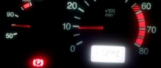
Engine speed fluctuates: symptoms and main causes
First of all, the tachometer helps to notice floating speed. Most often, the floating speed appears at idle. Normally, even on a slightly warmed-up engine, the tachometer needle should remain stable at about 800 rpm while idling.
The only exception is the warm-up speed XX, when the ECU on injection engines itself raises the speed to 1000-1100 rpm. In this case, after the engine temperature rises slightly, the control unit will lower the idle speed to the desired level of 750-800 rpm.
Also, jumps in speed can be observed if you increase the load on the engine (press the brake pedal, turn the steering wheel in a car with hydraulic booster, turn on the air conditioning or climate control, etc.). The revolutions may also fluctuate while driving in transition modes.
In this case, without additional load, the engine can keep the speed stable at idle, but as soon as the load appears, the speed drops, and the engine almost or completely stalls.
The driver may also notice a significant increase in fuel consumption, the engine response changes when exiting transient modes, jerks and dips may occur during acceleration, etc.
Throttle Position Sensor (TPS)
Purpose - fixing the position of the throttle valve at a certain point in time. In this case, the position changes taking into account where the gas pedal is located and how open the throttle is.
It is believed that when installing a high-quality sensor on a machine, there should be no difficulties in operation. But this does not always happen, because there are many fake TPS on the market (for example, from China).
Their disadvantage is a short service life and a large error even with proper operation of the motor.
Even with a partial malfunction of the sensor that controls the throttle valve, difficulties arise in driving the car. For example, dips in pressing and “floating” revolutions occur.
In addition, if the TPS fails, there is a high risk of jerks and dips when the engine operates in motion. In simple words, the gas pedal becomes uninformative and begins to act weird.
There are known situations where the device broke down while washing the engine under high jet pressure.
There are often situations when the sensor completely flies away from its installation site. To avoid such problems, you need to ensure that washers act carefully and do not direct a direct stream into the engine compartment.
As a rule, the original TPS installed at the factory does the job well and rarely breaks down. If such a problem occurs, the only solution is replacement. There is no point in repairing the device.
Sensor failure can be determined by the following signs:
- detonation in the engine when accelerating;
- increase in speed at idle;
- reduction in power of the power unit and decrease in throttle response;
- motor overheating;
- jerking when releasing gas;
- increasing the “gluttony” of the car;
- engine stops working when changing gears;
- jerks and dips when pressing the gas;
- other signs of a malfunctioning throttle position sensor.
In most cases, a malfunction of the TPS manifests itself by an increase in speed and the inability to brake with the engine.
To avoid problems in the future, you need to understand the reasons why this happens.
The main ones include:
- breakdown of the moving contact and the appearance of scoring;
- oxidation of the contact group and the appearance of a layer of rust (requires sedum cleaning with WD and a clean rag);
- incomplete closing of the throttle valve at idle;
- wear of the sensor substrate in the presence of sputtering on the resistive layer, which can be corrected using tweezers.
Tips and tricks
Let's look at how you can eliminate some of the malfunctions that lead to floating and speed jumps, and do it yourself.
- As mentioned above, the leakage of excess air can cause surges. To exclude or confirm the possibility of supplying such air, you need to check the tightness of the air supply system to the intake. You can remove the air hose and feed it air from a compressor or pump by placing the hose in a container of water. This method helps to identify cracks.
- As for the idle air control, you need to measure the resistance with a multimeter. If the resistance is between 40 and 80 ohms, this means that the device is not working.
- Also, as part of diagnostic procedures, in some cases it is necessary to clean the crankcase ventilation valve. The valve must be removed and washed with carburetor cleaning fluid or kerosene. This approach will remove deposits from the valve.
- As for the ECM sensors, in this case it is not advisable to try to repair such elements. For example, if the mass air flow sensor is faulty, it is better to immediately replace it with a new one.
- It is better to trust specialists to flush the throttle valve without proper experience, especially if such flushing is necessary with the removal of the valve. If we talk about the method of flushing the throttle without removing it, you can do the procedure yourself. The hoses are disconnected from the valve, then a cleaning aerosol is injected into the throttle.
The main thing is to disconnect the electrical contacts from the throttle valve. Let us add that on many cars where the damper was heavily dirty, you then need to additionally set the correct opening gap of the damper or “teach” the throttle using the appropriate equipment.
- On a car with a carburetor, you need to adjust the idle speed by setting it with the quality and quantity screws on the carburetor. The idle jet may also need to be cleaned. To do this, it is often enough to inject a carburetor cleaning aerosol and then blow it with compressed air.
According to drivers, this helps protect the pump from corrosion and is a preventative measure. At the same time, we note that this method is suitable for construction equipment and it is highly not recommended to practice such solutions on modern diesel internal combustion engines.