Combustible mixture composition
The combustible mixture consists of fuel vapor and air.
The working process in the cylinders of a gasoline engine proceeds very quickly; each stroke in an engine operating at a crankshaft speed of 2000 rpm is completed in 0.015 seconds.
The combustion of liquid fuel occurs relatively slowly, and it is necessary that the combustion of the fuel in the cylinder occurs in a shorter time than any stroke. It is possible to increase the combustion speed to 25-30 m/sec only if the liquid fuel is crushed into tiny droplets and then evaporated. The formation of tiny droplets is achieved by atomizing and evaporating fuel, and rapid combustion occurs due to thorough mixing of these vapors with the required amount of air.
For complete combustion of fuel, a strictly defined amount of oxygen in the air is necessary. If there is not enough air, then all the fuel will not be able to burn; if there is an excess of air, all the fuel burns, but there is still some unused oxygen in the air.
For complete combustion of fuel, a strictly defined amount of oxygen in the air is necessary. If there is not enough air, then all the fuel will not be able to burn; if there is an excess of air, all the fuel burns, but there is still some unused oxygen in the air.
It has been established that for the combustion of 1 kg of fuel it is necessary to have 15 kg of air. A mixture of this composition is called normal (stoichiometric). However, with a ratio of 1:15, complete combustion of the fuel does not occur and part of it is wasted aimlessly.
For complete combustion, the ratio of fuel and air should be 1:17 - 1:18, such a mixture is called lean. Due to excess air in a lean mixture, its calorific value decreases, which leads to a decrease in the combustion rate and a decrease in engine power.
To increase engine power, the mixture must burn at the highest speed, and this is possible with a fuel-to-air ratio of 1:13; such a mixture is called enriched. With this composition of the mixture, complete combustion of the fuel does not occur and the engine’s efficiency deteriorates, but it is possible to obtain the greatest power from it.
When the fuel to air ratio is less than 1:13, the combustion rate decreases, engine efficiency and power decrease. A mixture of this composition is called rich. If the ratio of fuel and air in the mixture is more than 1:18, its combustion rate also decreases sharply, which also leads to a loss of efficiency and power. A mixture of this composition is called lean.
When the air content in the mixture is less than 6 kg per 1 kg of fuel or more than 20 kg per 1 kg of fuel, the combustible mixture in the cylinders does not ignite.
In a running engine, there are usually five main modes: cold starting, low speed operation (idling), partial load operation (medium load), full load operation and operation at a sharp increase in load or speed. For each mode, the composition of the mixture should be different.
When starting a cold engine, the mixture formation conditions are very poor: the engine is cold, most of the fuel condenses on the cylinder walls and in the intake manifold, and the air flow speed is low, since the engine crankshaft rotates at a low number of revolutions. To ensure starting of a cold engine, the mixture must be rich in order to compensate for that part of the fuel that condenses on the cylinder walls.
At low idle speeds, the conditions for mixture formation are also poor due to insufficient cleaning of the cylinders from exhaust gases. The amount of mixture in this mode should be small, but its qualitative composition should be enriched.
At average loads, full engine power is not required and to save fuel the mixture should be lean, i.e. one that burns completely.
At full load, the mixture must have the highest combustion rate in order to get the most power from the engine. A rich mixture satisfies these conditions, but the engine operates less economically than at average loads.
If the load or crankshaft speed suddenly increases, the mixture must be richer, otherwise the engine will stop.
CHAPTER 6. FUEL AND ENGINE POWER SYSTEM
Home / Publications / Literature / Bookshelf / A. Agatov. Outboard motorsFuel and its combustion.
In outboard motor engines, exclusively light liquid fuels are used to prepare the combustible mixture, i.e., light fractions of oil - gasoline, gasoline, kerosene; or light fractions of coal - benzene, toluene; or various alcohols; or, finally, mixing them with each other in a certain proportion.
The main requirements for fuel are: 1) high calorific value; 2) good starting qualities, depending on evaporation; 3) high auto-ignition temperature; 4) high anti-explosion (anti-knock) properties; 5) the absence of impurities that contribute to the deposition of soot on the walls; 6) physical and chemical homogeneity and stability.
One of the main types of fuel for outboard motor engines that meets these requirements is gasoline.
Engines running on light fuels are called light engines
. These also include outboard motors that run on A-66, A-70, A-74 gasoline (GOST 2084-46).
For sports engines, 1st grade motor gasoline and aviation gasoline of the B-70, B-74 and B-78 brands, which allow higher compression ratios, are more often used.
At sports competitions, they often resort to fuel mixtures, which, in addition to gasoline, contain benzene and toluene in significant quantities.
Alcohol is often used as fuel for outboard motors. Alcohol allows for a higher degree of compression.
To completely burn one kilogram of gasoline, theoretically, about 15 kg of air is required. This mixture is called “normal”. However, it does not always meet the requirements. The greatest power is obtained with enriched mixtures, that is, when less air is given per 1 weight part of fuel than with a normal mixture. But such power is uneconomical and leads to excessive fuel consumption. When the fuel and air ratio is 1:6, the mixture stops burning altogether. At partial load and low speed, you should switch to lean mixtures, when the fuel to air ratio is brought to 1: 16 - 1: 17; above 1:17, the mixture becomes over-lean and power is greatly reduced, the engine begins to operate intermittently and overheats due to the slow burning of the mixture and its burning out at the outlet. When the fuel to air ratio is 1:21, the combustible mixture stops burning.
At different operating modes of the engine, the most appropriate composition of the working mixture should be used: at full load - rich, at medium and low - lean. When warming up the engine and when starting, you should always run on a rich mixture, since some of the gasoline in a cold engine will not have time to evaporate and burn completely. When the engine is warm and idling, in order to obtain stable operation at minimally low speeds, it is necessary to use an enriched mixture, throttling the charge.
Self-ignition of the mixture and detonation in the engine. We have already talked about the advantages of running the engine at high compression ratios.
Depending on the type of gasoline, the compression of the mixture in the cylinder is usually brought to a pressure of 7-9 atm, which raises the temperature of the fresh charge to approximately 600-650°. Higher temperatures for regular gasoline already result in self-ignition of the working charge, i.e., a flash of the combustible mixture in the cylinder much earlier than the spark in the cylinder plug.
Self-ignition occurs only in an overheated engine, at a flame propagation speed in the cylinder equal to approximately 30-40 m/sec, i.e., the combustion speed of a normal mixture when it is ignited by a spark.
Self-ignition always occurs before TDC. It is accompanied by dull knocks at TDC, rough operation and then a sudden stop of the engine. If you turn off the ignition, then during self-ignition the engine may still make a few pops before stopping.
Detonation, on the contrary, is also possible in a non-overheated engine. It is a consequence of flame propagation at an extremely high speed, on the order of 2500-4000 m/sec (blast wave speed). The essence of detonation is that in the presence of high temperatures, and mainly high pressures, fuel hydrogen molecules, combining with air oxygen molecules, produce a new chemical compound - “peroxides,” a very unstable explosive. When detonating gas burns in waves, hitting the walls of the cylinder and piston, it creates large local pressures that disrupt the smooth operation of the engine. Detonation is accompanied by a sharp metallic knock due to vibration of the cylinder walls and crank mechanism, which is not similar to knocks from self-ignition. The carbon remaining after the combustion of peroxides does not burn completely due to the lack of oxygen used for the formation of peroxides, and is ejected from the exhaust pipe in the form of soot; in this case, there is an increased transfer of heat from the gas to the cylinder walls and the piston. As a result, the engine overheats, fuel consumption increases, and power decreases. The consequence of overheating and high detonation pressures is piston burnout, cracks in the head and piston bottom, destruction of spark plug insulation, burning of spark plug electrodes and high engine wear.
Detonation can be eliminated partly by enriching the mixture, i.e. by increasing fuel consumption, reducing ignition timing, throttling the engine, and reducing the load. The main measure to combat detonation is the selection of fuel that is less detonating.
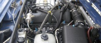
Supply system.
The outboard motor power system consists of a gasoline tank, a gas tap with a sump and filter, a gas line pipe and a carburetor with a suction pipe and an air filter.
Gas tank
(Fig. 28). The purpose of a gas tank is to supply fuel to the engine while it is running and to store fuel while the ship is voyaging. For lightness, the gas tank is made of sheet steel or AMC aluminum alloy. The latter is installed on our domestic engines LMM-6 and LMR-6. Its volume is 8 liters. This volume of fuel is usually enough to run the engine for 1.5-2 hours.
At the top for filling gasoline, a neck 1 is welded with a cap 3 that screws onto it and a sealing ring 2 that does not allow gasoline to spill out through the thread. In the middle of plug 5 there is a shut-off valve with cone a, pressed by a spring to its seat, so that during parking, with the engine tilted, gasoline cannot spill out. During operation, this valve is lifted and rotated 90°. The valve is supported by a pin 4 on the end of the plug, which keeps it open during the entire engine operation, as a result of which the internal cavity of the tank communicates with atmospheric air and the loss of gasoline does not affect the pressure inside the tank.
To prevent the cap from being dropped into the water when refueling the engine with gasoline, it is equipped with a chain with an expanding pin 7.
Rice. 28. Gasoline tank of the LMR-6 engine: 1 - neck; 2 - sealing ring; 3 - cover; 4 — hairpin; 5 - plug; 6 - shut-off valve; 7 — expansion pin; 8 - ribs; 9 — fitting; 10 — gas tap; 11 - filter; 12 - settling tank; 13 — tap handle; 14 - tap; 15 - handle; a - shut-off valve leak; b - drilling to the sump and filter; c - valve bypass hole; g - channel supplying gasoline from the tank to the tap
A fitting 9 is welded to the bottom of the tank under the gas tap 10. The latter is equipped with a tap 14 with a handle 13 for turning the tap to position “3” - closed, “O” - open, “P” - reserve. When “O” - the valve is open, it communicates with the tank with drilling b, supplying gasoline to the sump and filter. A sump 12 and a filter 11 are placed at the bottom of the tap.
The gas valve communicates with the carburetor via a gas-resistant rubber tube.
The tank is attached to the engine on the LMM-6 and LMR-6 engines with four bolts or rivets to ribs 8 welded to the tank.
A handle 15 is welded to the tank, helping to carry and install the motor on the boat; use the handle to turn the engine when refueling and when reversing; it serves as a support. when the motor is placed on the ground.
Carburetor and carburetion.
The process of forming a working mixture is called carburetion, and the device that prepares the combustible mixture and regulates its composition is called a carburetor. A properly constructed carburetor should automatically mix gasoline vapors with air in the required proportions, preparing a combustible mixture of the required composition for different operating modes.
Currently, carburetors are used that are built exclusively on the atomizing (spraying) principle.
Since the engine on a ship almost always operates in one, most favorable mode (the efficiency of the propeller also requires this), they prefer to use a simple carburetor for outboard motors, as opposed to automobile, motorcycle and other transport engines operating at variable modes and loads.
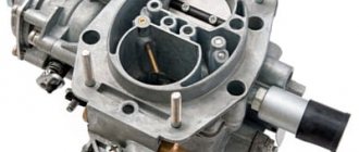
Our domestic engines LMM-6 and LMR-6 use a carburetor of the K-30 type, modernized, produced by the Leningrad carburetor. Its design is shown in Fig. 29.
Its main parts are: the carburetor body, which contains a float chamber a and a mixing chamber b; air inlet and outlet pipes and channels for the passage of gasoline; float chamber cover with gas receiver 14 and quencher 13; spool with metering needle 9 and adjusting rail 11; gear adjustment control sector 12 with handle; air intake with cap 15, air supply regulator 16 and metal air filter e; float 6 with shut-off needle; jet 7; settling plug 8.
The principle of operation of the carburetor is as follows: fuel from the gas tank through a gas-resistant rubber tube, through a gas receiver with a narrow channel, enters the float chamber a and fills it. When gasoline reaches a certain level in the float chamber, the float needle 5 closes the channel and the access of gasoline to the float chamber is stopped.
Rice. 29. Carburetor type K-30: 1 - air intake; 2 - rail; 3 — mixing chamber cover; 4 - spool; 5 - locking needle; 6 — float; 7 - jet; 8 — nozzle plug; 9 — dosing needle; 10 — carburetor body; 11 — adjusting rail; 12 — gear sector; 13 - quencher; 14 — gas receiver; 15 — cap; 16 — air supply regulator; a — float chamber; b - mixing chamber; c — diffuser; g — regulator inlet window; d — inlet window of the air intake; e - air filter
From the float chamber, fuel enters the mixing chamber through a nozzle. A spool with a metering needle is placed in the mixing chamber. There is a cutout in the front of the spool that plays the role of a diffuser. An air inlet 1 and a cap 15 are placed in front of the diffuser. The latter protects the mixing chamber from splashes of water entering it. The air regulator is rigidly attached to the cap. By turning the cap by hand, the air regulator is turned, blocking the air intake windows. The air passes through the filter e, enters the diffuser b, and sprays the gasoline flowing through the nozzle, forming a flammable mixture. The mixture, under the influence of vacuum, enters the crankcase through the suction pipe and then through the suction windows.
The quantity and quality of the mixture is adjusted by turning a gear sector with a handle, connected to a gear engagement with a cylindrical rack threaded into the spool. By raising the spool and at the same time the needle, the amount of air and fuel entering the engine is regulated.
To enrich the mixture at startup, a quencher is placed on the lid of the float chamber, pressing on which deepens the float and thereby opens access for an additional portion of gasoline into the float chamber, due to which the level in the latter rises. The amount of fuel sprayed into the mixing chamber mainly depends on the height of the gasoline level in the float chamber and the speed of the air stream passing near the nozzle, which is how enrichment of the mixture is achieved. By increasing or decreasing the flow of the finished mixture into the cylinder by opening the spool more or less, we influence the engine speed and power. One of the main requirements for a carburetor is to maintain a constant composition of the working mixture in all engine operating modes, which is achieved by adjusting the opening of the spool together with the metering needle. The needle is adjusted so that each lift of the spool corresponds to its own gasoline flow rate, ensuring the normal composition of the working mixture in all engine operating modes.
The air regulator allows you to change the established quality mixture adjustment in one direction or another, making it richer or leaner at the driver’s discretion.
Forward Contents Back
The influence of a violation of the composition of the working mixture on engine operation
Malfunctions of the power system include the formation of a mixture of inadequate quality and increased fuel consumption. The most common malfunctions of the power system include the formation of a rich or lean combustible mixture.
A rich working mixture has a reduced combustion rate and causes the engine to overheat, and its operation is accompanied by sharp popping noises in the muffler. Popping appears as a result of incomplete combustion of the mixture in the cylinder (there is not enough air oxygen), and it burns out in the muffler, accompanied by black smoke.
Long-term operation of the engine with a rich mixture leads to excessive fuel consumption and large deposits of carbon deposits on the walls of the combustion chamber and the electrodes of the spark plugs. The formation of a rich combustible mixture is facilitated by a decrease in the amount of incoming air or an increase in the amount of incoming fuel.
A lean combustible mixture also has a reduced combustion rate, the engine overheats, and its operation is accompanied by sharp popping noises in the intake manifold. The popping noise appears as a result of the mixture still burning out in the cylinder when the intake valve is already open and the flame spreads into the intake manifold.
Running the engine for a long time on a lean mixture also causes excessive fuel consumption due to the fact that engine power in this case drops and you have to use lower gears more often. The formation of a lean combustible mixture is facilitated by either a decrease in the amount of incoming fuel or an increase in the amount of incoming air.
ICE working mixture
The very name of combustion engine - INTERNAL COMBUSTION - hints that something is burning there. And, of course, it is not the fuel itself that burns, but only its vapor mixed with air. This mixture is usually called working. The combustion of this mixture has a peculiarity - it burns, significantly increasing in volume, creating, so to speak, a shock wave for the cylinder pistons.
The carburetor or injector is responsible for creating the working mixture, respectively, depending on the type of engine.
Detonation and spontaneous combustion
Under normal conditions, combustion of the working mixture in the engine cylinders occurs at a speed of 25-30 m/sec and the pressure in the cylinder increases smoothly. The engine operates in normal thermal conditions, without knocking or failure.
When using lower quality fuel, overheating the engine, or setting a very early ignition point, the mixture begins to burn at a speed reaching up to 2000 m/sec. This explosive combustion of the mixture is called detonation. During detonation combustion, the pressure in individual parts of the cylinder increases sharply, metallic knocks appear, engine power drops, and black smoke appears from the muffler. The most harmful phenomenon of detonation affects the condition of the parts of the crank mechanism, where destruction of individual parts is possible.
The tendency of a fuel to detonate is conventionally assessed by its octane number. The higher the octane number, the less prone the fuel is to detonation. Gasoline with a higher octane number is used for engines with a higher compression ratio.
Detonation combustion of a mixture is sometimes mistakenly confused with self-ignition or glow ignition. Self-ignition can occur in the cylinders of an overheated engine at a time when the electric spark has not yet entered the cylinder, as well as during ignition from hot carbon particles or spark plug electrodes. In both cases, the mixture burns at normal speed. This phenomenon is usually observed when the ignition is turned off, while the engine continues to run for some time.
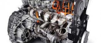
Engine operating principle
The operating principle of classical internal combustion engines is based on the conversion of fuel flash energy - thermal energy released from fuel combustion - into mechanical energy.
However, the process of energy conversion itself may differ.
The most common option is this:
- The piston in the cylinder moves down.
- The inlet valve opens.
- Air or a fuel-air mixture enters the cylinder. (under the influence of the piston or piston and turbocharging system).
- The piston rises.
- The exhaust valve closes.
- The piston compresses the air.
- The piston reaches top dead center.
- The spark plug fires.
- The exhaust valve opens.
- The piston begins to move upward.
- Exhaust gases are forced into the exhaust manifold.
Important!
If diesel fuel is used, then the spark does not take part in starting the engine; diesel fuel ignites itself during compression.
At the same time, to understand the operating principle, it is important not just to take into account the physical sequence, but to keep the entire control system under control. The diagram of the ELECTUDE training module helps to understand it clearly.
Please note that in distance learning courses on the ELECTUDE platform, when studying the diesel engine control system, it is deliberately analyzed separately from the fuel injection control system. A very smart approach. It is really difficult for many students to immediately understand both the control system and the injection system. And in order to master the material well, it is necessary to move competently step by step.
But let's return to the operation of the engine itself. The considered operating principle is relevant for most internal combustion engines, and it is reliable for any vehicle, including trucks.
In fact, devices operating on this principle operate on 4 strokes (which is why most motors are called four-stroke):
- Release stroke.
- Air compression stroke.
- The actual working stroke is the very moment when the energy from fuel combustion is converted into mechanical energy (to start the crankshaft).
- The opening stroke of the exhaust valve is necessary to ensure that the exhaust gases leave the cylinder and make room for a new portion of the mixture of fuel and air
4 strokes form a duty cycle.
In this case, three beats are auxiliary and one is directly giving impetus to the movement. Visually, the operation of the four-stroke model is presented in the diagram.
But the work can be based on another principle - push-pull. What happens in this case?
- The piston moves from bottom to top.
- Fuel enters the combustion chamber.
- The piston compresses the fuel-air mixture.
- Compression occurs. (pressure).
- A spark appears.
- The fuel ignites.
- The piston moves down.
- Access to the exhaust manifold is provided.
- Combustion products exit the cylinder.