Crankshaft and flywheel
The crankshaft is a five-bearing one, cast from cast iron. The surfaces of the shaft journals are hardened by high-frequency currents to a depth of 2–3 mm. At the rear end of the crankshaft there is a seat for the front bearing of the gearbox drive shaft, along the outer diameter of which the flywheel is centered.
The connecting rod and main journals of the crankshaft are connected by channels through which oil is supplied to lubricate the connecting rod bearings. The technological outlets of the channels are closed with cap plugs, which are pressed in and caulked at three points for reliability.
To extend the service life of the crankshaft, it is possible to regrind the crankshaft journals when their surfaces are worn or damaged. By grinding, the journal diameters are reduced by 0.25, 0.5, 0.75 and 1.00 mm.
Main and connecting rod bearing shells
The main and connecting rod bearings are made of steel and aluminum. The upper shells of the 1st, 2nd, 4th and 5th main bearings have a groove on the inner surface, and the lower ones without a groove (until 1987, the lower shells of these bearings were installed with a groove). The shells of the central (3rd) main bearing differ from the others in their larger width and the absence of a groove on the inner surface. All connecting rod bearing shells are without grooves, identical and interchangeable.
The flywheel is cast from cast iron and equipped with a steel ring gear for starting the engine with a starter. The flywheel is installed on the crankshaft so that the mark (a cone-shaped hole near the ring gear) is located against the connecting rod journal of the 4th cylinder. The mark is used to determine the TDC in the first and fourth cylinders.
Cleaning the lubrication system channels
1. To clean, remove the channel plugs. Then drive the plug sockets with a countersink A.94016/10, put on the A.94016 spindle, thoroughly rinse the channels with gasoline and blow with compressed air.
2. Apply UG-6 sealant to the surfaces of the plug sockets. Using mandrel A.86010, press in new plugs and, for greater reliability, caulk each plug at 3 points with a center punch.
Checking the main and connecting rod journals
1. Install the crankshaft on two prisms (see Fig. Permissible runout of the main surfaces of the crankshaft) and check with an indicator:
runout of the main journals (maximum permissible 0.03 mm); runout of the seating surfaces under the sprocket and gearbox input shaft bearing (maximum permissible 0.04 mm); displacement of the axes of the connecting rod journals from the plane passing through the axes of the connecting rod journals and main journals (maximum permissible ±0.35 mm); non-perpendicularity of the end surface of the flange with respect to the axis of the crankshaft. When turning the shaft, an indicator installed on the side at a distance of 34 mm (see Fig. Permissible runout of the main surfaces of the crankshaft) from the shaft axis should not show a runout of more than 0.025 mm.
Permissible runout of the main surfaces of the crankshaft
2. Cracks are not allowed on the main journals, connecting rod journals and on the cheeks of the crankshaft. If any are found, replace the shaft.
3. Scratches, nicks and risks are not allowed on the surfaces of the crankshaft mating with the working edges of the oil seals.
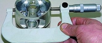
4. Measure the diameters of the main and connecting rod journals. The journals should be ground if their wear is more than 0.03 mm or the ovality of the journals is more than 0.03 mm, and also if there are burrs and marks on the journals.
Source
Repair size of crankshaft
Remove the connecting rod cover along with the liner
Disconnect the remaining connecting rods from the crankshaft and move them up
We remove the liners from the connecting rods and their caps.
Using a 17 mm socket wrench, loosen the bolts securing the crankshaft main bearing caps
After unscrewing the two bolts, remove the rear main bearing cover. Two thrust half-rings are installed in the grooves of the rear crankshaft support. The front ring A is steel-aluminum, and the rear ring B is metal-ceramic. The rings can be removed by pressing on their ends with a thin screwdriver.
We unscrew the bolts of the remaining main bearing caps, keeping the crankshaft from falling. We remove the covers one by one and remove the crankshaft from the engine crankcase. All cover liners (except for the third one), installed in the main bearing beds, have a groove. The main bearing caps have marks corresponding to their serial number (counted from the toe of the crankshaft), facing the left side of the cylinder block. The fifth cover has two marks spaced along the edges.
Selection of crankshaft liners
In most cases, the selection is entrusted to a specialist. But after studying the information in detail, you will be able to do this on your own. In addition to the fact that it is necessary to combine spare parts with the car model, the general condition of the vehicle is also taken into account.
Selection of main liners
Some useful recommendations for selecting a new HF when replacing the crankshaft liners:
- it is better to buy basic elements of the same color as the standard ones (used, old);
- Be sure to check the markings directly on the shaft.
A special identification color selection card is issued for main bearings. For example, for a 4-cylinder engine, the markings applied to the BC and the CV assembly are used. If marked C3, then you can install yellow and green elements. More details about the colors in the picture below.
And this is an identification card for 6-cylinder engines.
Selection of connecting rod bearings
And here, if the HF is new, the plain bearings are selected according to the diagram. If the color code is lost, you need to look at the markings on the connecting rod caps.
Below is an identification card for selecting connecting rod half rings for four-cylinder power units.
And this is the color map for 6-cylinder units.
The choice of bearings also depends on the antifriction coating. As a rule, it consists of several layers:
- biometallic with a steel base (1-4 mm) - lead, copper, zinc, tin, silicon and aluminum;
- trimetallic - lead, tin, copper.
Use the correct engine oil that meets all the requirements and approvals of the engine manufacturer. It is also necessary to update the filter promptly to prevent abrasive particles from entering the lubricant. It is also not recommended to overload the engine. All this will extend the service life of the liners by almost 2-3 times.
Why is a crankshaft needed in a VAZ 2106 engine?
The crankshaft (crankshaft) is an important part of the crank mechanism of any engine. The operation of the unit is aimed at converting the energy of combustion gases into mechanical energy.
Description of the VAZ 2106 crankshaft
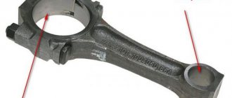
The crankshaft has a rather complex design, with connecting rod journals located on the same axis, which are connected through special cheeks. The number of connecting rod journals on the VAZ 2106 engine is four, which corresponds to the number of cylinders. Connecting rods provide connection between the journals on the shaft and the pistons, resulting in reciprocating movements.
Let's look at the main elements of the crankshaft:
Seals are installed in front and behind the crankshaft - oil seals, which prevent oil from escaping out. The entire crankshaft mechanism rotates thanks to special plain bearings (liners). This part is a thin steel plate that is coated with a low-friction material. To prevent the shaft from moving along the axis, a thrust bearing is used. The material used in the manufacture of the crankshaft is carbon or alloy steel, as well as modified cast iron, and the production process itself is carried out by casting or stamping.
The crankshaft of the power unit has a complex structure, but the principle of its operation is quite simple. In the engine cylinders, the fuel-air mixture ignites and burns, resulting in the release of gases. During expansion, the gases exert an impact on the pistons, which leads to translational movements. Mechanical energy from the piston elements is transferred to the connecting rods, which are connected to them through the bushing and piston pin.
An element such as a connecting rod is connected to the crankshaft journal using a liner. As a result, the translational movement of the piston is converted into rotation of the crankshaft. When the shaft makes a half revolution (turns 180˚), the connecting rod journal moves back, thereby ensuring the return of the piston. Subsequently, the cycles are repeated.
No less important in the operation of the crankshaft is the process of lubrication of rubbing surfaces, which include the connecting rod and main journals. It is important to know and remember that lubricant is supplied to the shaft under pressure created by the oil pump. Oil is supplied to each main journal separately from the general lubrication system. Lubricant is supplied to the connecting rod journals through special channels located in the main journals.
Neck sizes
The main and connecting rod journals wear out as the engine operates, which leads to disruption of the proper operation of the power unit. In addition, wear can be associated with various types of engine problems. These include:
The listed nuances lead to damage to the surface of the shaft journals, which indicates the need for repair or replacement of the unit. To assess the wear of the journals, you need to know their dimensions, which are shown in the table.
Table: crankshaft journal diameters
| Connecting rod | Indigenous | ||||||||
| Nominal | Repair | Nominal | Repair | ||||||
| 0,25 | 0,5 | 0,75 | 1 | 0,25 | 0,5 | 0,75 | 1 | ||
| 47,814 | 47,564 | 47,314 | 47,064 | 46,814 | 50,775 | 50,525 | 50,275 | 50,025 | 49,775 |
| 47,834 | 47,584 | 47,334 | 47,084 | 46,834 | 50,795 | 50,545 | 50,295 | 50,045 | 49,795 |
What to do when necks wear out
What are the steps to take if the crankshaft journals are worn out on a VAZ 2106? First, the defectiveness is carried out, measurements are taken using a micrometer, after which the crankshaft journals are polished using special equipment to the repair size. This procedure cannot be done in a garage environment. The necks are ground to the closest size (based on the tables provided). After processing, thickened liners (repair) are installed in accordance with the new size of the necks.
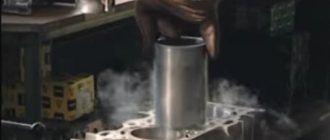
If a major overhaul of the engine is being carried out, it would not be superfluous to inspect the oil pump, blow out the oil passages of the cylinder block, as well as the crankshaft itself. Attention should be paid to the cooling system. If there are signs of wear or damage on the engine elements or its systems, the parts and mechanisms need to be repaired or replaced.
Video: grinding the crankshaft on a machine
Crankshaft selection
The need to select a crankshaft for a VAZ 2106, like for any other car, arises in case of engine repair or to improve engine performance. Regardless of the task at hand, it must be remembered that the crankshaft must be heavy, with large counterweights. If the part is selected correctly, mechanical losses will be significantly reduced, as well as other loads on the mechanisms.
In the process of selecting a unit, even if it is new, close attention is paid to its surface: there should be no visible flaws, such as scratches, chips, or burrs. In addition, attention is paid to a number of crankshaft characteristics, namely coaxiality, ovality, taper and journal diameter. During engine assembly, the crankshaft is balanced to balance all rotating elements. A special stand is used for this procedure. Once balancing is completed, secure the flywheel and continue the process again. Afterwards, the clutch basket and other elements (pulleys) are mounted. There is no need for balancing with the clutch driven disc.
Marking of inserts for VAZ 21083
Piston with connecting rod. Disassembly, troubleshooting and assembly Piston with connecting rod:1 - connecting rod bolt nut 2 - connecting rod bearings 3 - connecting rod 4 - piston pin 5 - outer compression ring groove 6 - lower compression ring groove 7 - oil scraper ring groove 8 - piston 9 - connecting rod bolt 10 - connecting rod cap
For the convenience of selecting pistons for cylinders, cylinders and pistons, depending on the diameter, are divided into five size groups: A, B, C, D, E.
Pistons of nominal sizes of three classes are supplied as spare parts: A, C, E and two repair sizes. The first repair value is increased by 0.4 mm, the second – by 0.8 mm. By weight, pistons are divided into three groups: normal, increased by 5 g and decreased by 5 g. Pistons of a single group must be installed on the engine. For repair size pistons, repair size rings increased by 0.4 mm and 0.8 mm are supplied as spare parts. The number “40” is stamped on the rings of the first repair size, and “80” on the second.
Nominal sizes of cylinders and pistons Size group Model of the VAZ-2108 engine Model of the VAZ-21083 engine
Cylinder diameter, mm Piston diameter, mm Cylinder diameter, mm Piston diameter, mm
A 76.00-76.01 75.965-75.975 82.00-82.01 81.965-81.975
B 76.01-76.02 75.975-75.985 82.01-82.02 81.975-81.985
C 76.02-76.03 75.985-75.995 82.02-82.03 81.985-81.995
D 76.03-76.04 75.995-76.005 82.03-82.04 81.995-82.005
E 76.04-76.05 76.005-76.015 82.04-82.05 82.005-82.015 To select pistons for cylinders, calculate the gap between them. The gap is defined as the excess between the measured diameters of the piston and cylinder. The nominal gap is 0.025-0.045 mm, the maximum permissible is 0.15 mm. If the gap does not exaggerate 0.15 mm, pistons can be selected from subsequent classes to keep the gap as close to nominal as possible. If the gap exceeds 0.15 mm, bore the cylinders to the next repair size and install pistons of the corresponding repair size.
Note 1 Gap between rings and piston grooves, mm
Nominal: upper compression ring 0.04-0.075 lower compression ring 0.03-0.065 oil scraper ring 0.02-0.055 Maximum permissible gap for all rings 0.15, Note 2 Gap in piston ring locks, mm:
Maximum permissible 1.0 Piston pins are divided by diameter into three classes (1st, 2nd, 3rd) every 0.004 mm. The discharge of the finger is marked on its end with paint.
Size classes of piston pins and pistons Type Pin diameter, mm Hole diameter in piston, mm Piston pin marking
1 21,970-21,974 21,982-21,986 Blue 1
2 21,974-21,978 21,986-21,990 Young 2
3 21,978-21,982 21,990-21,994 Red 3
The piston is installed on the connecting rod so that the arrow on the bottom of the piston is directed in the opposite direction from the part number cast on the connecting rod. If there is an opening on the lower head of the connecting rod for oil to escape, the arrow on the piston must be directed towards this opening.
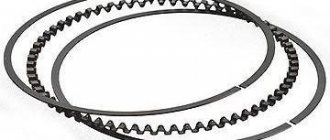
Procedure 1. We recommend removing the piston rings with a special puller. If it is not there, carefully push the ring lock apart and remove the ring from the piston. Remove the remaining rings in the same way. 2. Using a special mandrel, press the pin out of the connecting rod. 3. Examine the pistons. If they have scuff marks, burnout effects, or deep scratches, replace the pistons.
4. To determine the gap, check the cylinder diameter (see subsection 11.8.. and the piston diameter, which is measured with a micrometer in a plane perpendicular to the piston pin axis, at a distance of 51.5 mm from the piston bottom. 5. Check the gap between the rings and grooves with a feeler gauge piston in several places around the perimeter. If the gap exceeds the maximum permissible (see note 1), replace the pistons with rings. 6. Insert the piston ring into a special mandrel and check the gap in the lock. Instead of the mandrel, you can insert the ring into the cylinder and push it with the piston, so that the ring fits without distortion. If the gap exceeds the maximum permissible, replace the ring (see note 2). If the gap is less than 0.25 mm, carefully file the ends of the ring with a needle file.
7. Measure the fit of the piston pin in the piston. To do this, lubricate the piston pin with engine oil and insert it into the piston. The finger must enter the piston freely from pressure from the large finger of the hand. 8. Turn the piston over so that the pin stands vertically, but it does not have to fall out of the piston under the influence of its own weight. If the pin falls out of the piston, use the next class of pin. If the third class pin falls out of the piston, replace the piston and pin.
9. Examine the connecting rod bearings. If they have cracks, burrs, or chipping, replace the liners. 10. Examine the connecting rods with caps. Replace bent connecting rods. 11. Place piston pin 2 onto shaft 1 of the device for installing the piston pin with spacer ring 5 put on it. Next, put on guide sleeve 3 and secure it with screw 4 without tightening the screw. Dimensions of the spacer ring: outer diameter 22 mm, inner diameter – 15 mm, thickness – 4 mm. 12. Heat the upper head of the connecting rod to 240 ° C in the oven for 15 minutes. Clamp the connecting rod in a vice, place the piston on it (see note) so that the holes for the pin match, and insert the tool with the pin into the holes of the piston and connecting rod until the limit is reached. For correct installation of the pin, the piston must be pressed with the boss against the upper head of the connecting rod in the direction of pressing.
Crankshaft pulley
The generator and water pump on the VAZ 2106 are driven by a belt from the crankshaft pulley. When carrying out repair work on the engine, attention should also be paid to the condition of the pulley: is there any visible damage (cracks, scuffs, dents). If defects are found, the part should be replaced.
During the installation process, the pulley should sit smoothly on the crankshaft, without distortion. Despite the fact that the pulley fits quite tightly on the shaft, a key is used to prevent rotation, which can also be damaged. A defective part must be replaced.
Crankshaft marks
In order for the engine to work flawlessly, after installing the crankshaft, the correct ignition setting is necessary. There is a special casting on the crankshaft pulley, and on the cylinder block there are three marks (two short and one long) corresponding to the ignition timing. The first two indicate an angle of 5˚ and 10˚, and the long one - 0˚ (TDC).
The mark on the crankshaft pulley is located opposite the length of the marks on the cylinder block. There is also a mark on the camshaft sprocket that must be aligned with the casting on the bearing housing. To rotate the crankshaft, use a special wrench of the appropriate size. According to the marked marks, the piston of the first cylinder is at top dead center, while the slider on the ignition distributor must be installed opposite the contact of the first cylinder.
Despite the fact that the crankshaft is a critical component of any engine, even a novice auto mechanic can repair the mechanism, with the exception of the grinding stage. The main thing is to select the elements according to the dimensions of the shaft, and then follow the step-by-step instructions for assembling it.
Source