Starter Solenoid Relay Functions
Despite its apparent simplicity, the starter solenoid relay performs more than one function. Accordingly, when a part at least partially fails, the entire engine starting system fails. The functionality of the solenoid relay is partially clear from the name itself. Retractive means that it draws something in somewhere. Relay means switching (connection) of the power circuit of the vehicle's electrical equipment.
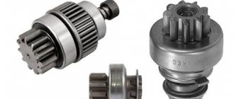
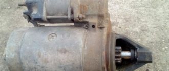
If you look at the general design of the starter, you can see that the solenoid relay pulls in. Its movable rod is connected through a lever to the overrunning clutch on the starter shaft. The overrunning clutch is made as one unit with the drive gear. When the retractor retracts its rod, the overrunning clutch and gear move forward, thereby engaging with the engine flywheel. The unit remains in this position until the driver releases the ignition key after successfully (or not) starting the engine.
The next function of the retractor relay is to disengage the drive gear from the flywheel when the engine is running. This is done due to the force of the spring. How the retractor retracts is discussed below. The overrunning clutch is needed in order to disconnect it from the starter shaft even before disengaging the drive gear.
Between retraction and retraction, the retractor relay performs an intermediate function. It consists in securely fixing the drive gear in engagement with the flywheel. If you do not do this, the gear will return to its original position before it was supposed to, and the engine will not have time to start. The holding coil of the solenoid relay, discussed below, is responsible for this function.
Well, the last two important functions of the solenoid relay are the connection of the “plus” of the battery with the starter and the reverse disconnection of the contact. Commutation occurs simultaneously with the drive gear being meshed with the engine flywheel. As a result, the starter armature begins to rotate in a timely manner, torque is transmitted to the crankshaft, and the engine starts. When the ignition key is released, the power “plus” of the battery is disconnected from the starter by the same solenoid relay.
In total, it turns out that such a simple device as a solenoid relay is assigned 5 functions:
- Retraction . The starter drive gear is engaged with the engine flywheel.
- Hold . The gear is securely locked in engagement with the flywheel.
- Reverse move . The gear is disengaged after the engine starts.
- Switching . The starter is supplied with starting current from the battery.
- Shutdown . Starter power is cut off.
The solenoid relay performs all these functions thanks to a simple, but at the same time ingenious device.
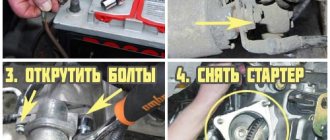
How to properly remove from the starter
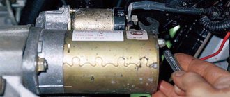
To check the solenoid relay with a multimeter, you need to remove it from the starter and be sure to mark the location of the armature relative to the housing. This is important because in some cases the bendix attachment point has an unusual shape. If you turn it the other way during assembly, problems may arise in its operation.
You can tap the heads of the screws with a hammer if you cannot budge them. When unscrewing the screws with a screwdriver, remember safety. Never hold the part with your left hand in line with the direction of the screwdriver. Otherwise, when you remove the screwdriver from the screw, with all the effort of your right hand, you will plunge a sharp metal sting into your left hand.
It is not difficult to use a multimeter; there is no particular danger in the device. Switch the device to the “dialing” mode. We check each winding separately.
The design and principle of operation of the retractor relay
Before checking the solenoid relay, it is simply necessary to become at least generally familiar with its internal structure. Of course, you won’t have to disassemble it, since the unit is considered non-separable. However, checking without understanding the device and operating principle can lead to dire consequences. Including inept actions, you can easily burn out the initially working solenoid relay.
Conventionally, its internal filling can be divided into three parts:
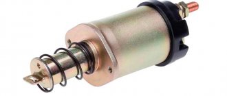
- Mechanical drive . Consists of two rods. One of them is removable (1). The second is located inside (10), and is driven by windings. Spring 11 is needed to return the starter drive gear to its original position after starting the engine.
- Windings . There are only two of them. Retracting (2) and holding (3). When an electric current passes through the winding, a powerful magnetic field is created in the area of the rod. When the retractor winding operates, rod 1 moves and the retractor retracts. When the gear is engaged with the flywheel, its fixation occurs due to the activation of the holding winding 3.
- Switching node . When the retractor retracts, rod 1 pushes rod 10 through the spring, due to which contact plates 9 connect contacts 6 to each other. The “plus” of the battery is connected to one of these contacts, and the second is connected to the starter. This is how the starter is energized (“minus” comes from ground). When the ignition switch is released, the holding winding is de-energized, rod 10 returns back under the influence of spring 7, and commutation stops.
Additionally, it is worth considering how the switching unit of the solenoid relay and its windings work. The diagram below shows how and where the current flows. When the driver turns the ignition key, both the retractor and retainer windings operate simultaneously. However, after connecting the “plus” of the battery with the starter, the retractor winding stops working, since the power “plus” is connected to the control “plus” through the relay contact. The holding winding continues to operate until the driver releases the ignition key.
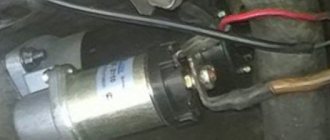
On a real retractor, the connection point between the retractor and retainer windings can be seen on the outside of the device. This is a metal jumper connecting one of the power contacts to the control one. It is to this power contact that the “plus” is connected to the battery. It follows that the power contact free from the jumper goes directly to the starter. Sometimes knowing this feature allows you to avoid mixing up the wires when installing and connecting the starter after checking.
That's all. This is exactly how a pull-in relay works. Now let's look at how it refuses to work, and what signs indicate which node malfunctions.
A little theory
In general, modern starters are equipped with a pair of relays. The first is responsible for turning on the unit. It is located directly in the engine compartment, and in some car models the relay is also placed in a separate housing. The second relay, called traction ( retractor ), is installed directly on the starter. This device has several functions:
- Ensuring synchronous operation of automobile starter components when starting the internal combustion engine;
- Electrical distribution energy between the electromagnetic relay and the starter motor;
- Ensuring the joint operation of the overrunning clutch and the flywheel ring (supply of gears) and, conversely, withdrawal of gears at the right time.
Here's how it all works: when the contacts in the ignition switch are closed, the usual starter relay is immediately activated, which is responsible for supplying voltage from the battery to the so-called. pull-in winding. As a result, a magnetic field is induced, acting on the relay armature, due to which it gets inside the winding. Now 2 actions are carried out at once: the starter fork begins to move, helping the overrunning clutch, also called the bendix, to move, and the contacts of the installed retractor relay close. Simply put: the starter is now connected to the flywheel, after which it is connected to the battery and by passing current through the circuit, the engine can now start. Do not forget that the operation of combustion systems without proper operation of the electrical circuits of the car is impossible.
However, this is not all. Now, when the starter turns on, due to the operation of the so-called. holding coil, the armature is held in its extreme position - in this mode of operation, the solenoid relay does not consume much energy. And if the engine is already running, the starter circuit is broken and the relay is de-energized. Automotive relays have a spring - it is this spring that, trying to compress, returns the armature to its initial position. Then the contact disk and bendix change their position. The battery turns off. Then the relay is no longer involved in the operation of the car until the engine is started.
Signs of a malfunctioning retractor relay
For clarity and ease of understanding, all common (and not so common) malfunctions of the solenoid relay with symptoms and causes are collected in the table below. The method for checking the starter solenoid relay is described below.
| Breaking | Sign |
| Break in the pull-in winding | The rod does not retract and the drive gear is connected to the flywheel, and the switching unit does not work - the starter is silent |
| Break in the holding winding | Clicking sounds are heard - this is the gear being engaged with the flywheel, but not fixed, but returns back under the influence of a spring |
| Interturn closure of the pull-in winding | It manifests itself in the fact that the retractor does not have enough strength to connect the starter to the engine, but very soon due to overheating the winding goes into a regular break |
| Interturn closure of the holding winding | The starter clicks, but does not turn, the solenoid relay gets terribly hot, and later the winding breaks due to overheating |
| Melting or oxidation of the switching unit | Due to the melting of the contact plates, the resistance of the power circuit increases, the starter turns hard or does not work at all |
| Switch node sticking | The starter continues to operate after the ignition key is released |
| Clogged or worn operating rod | Due to dust, dirt, dried lubricant, the winding force is not enough to sufficiently move the rod from its place, and accordingly, the starter does not turn the engine |
| Solenoid relay freezing | When turning the ignition key, the voltage on the on-board network drops sharply, but nothing happens - the retractor rod is jammed with ice (including water could get in and freeze in the drive mechanism) |
| Bad contacts | It manifests itself in different ways - the starter may work, but it is slow, or it does not work at all |
We finally move on to how to check the starter solenoid relay.
Signs and causes of violation
The relay stops working due to jamming, wear, open circuit or burnt contacts. Then, when you try to start the engine, the starter will start spinning without turning the crankshaft. If the part does not move, a click will appear, then the starter will still develop speed, but it is not enough to start. Also, in case of such violations, after the engine is ignited, the starter will continue to operate noisily and will not turn off.
Typically, drivers start looking for a breakdown in extreme cases, when the ignition stops working with one turn of the key. If it takes 2-3 attempts, then there is already cause for concern; there is no point in prolonging the situation.
Failure occurs due to one or more reasons:
- If there is poor contact or prolonged operation of the starter, which cannot start the engine, the connectors burn out.
- A short circuit occurs when the protective coating melts and one of the turns comes into contact with the housing.
- Spring breakage occurs periodically, but this is more often due to mechanical deformation. It occurs from severe overvoltage and burnout of the elements.
- If the engine regularly does not start the first time, then an interturn short circuit appears due to constant overvoltage of the parts. During this, the bakelite (coating of the wires) melts, the turns touch each other.
- Loose fastenings provoke distortion of the structure and the core no longer retracts back.
- A break in the winding occurs due to the burnout of one of the turns.
Checking the solenoid relay
Let's go from simple to complex. This should always be done to avoid, if possible, unnecessary manipulations. Moreover, checking the solenoid relay is far from a harmless procedure, and due to inexperience or carelessness, you can easily make it worse than it was. Injuries are also possible. Therefore, the malfunctions described in the table above will be considered from the end.
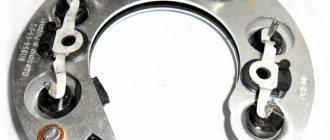
Checking the solenoid relay contacts
Checking the solenoid relay for bad contacts is carried out even without removing the assembly from the machine. To do this, you just need to unscrew three nuts from the back of the retractor, remove the control and power wires, inspect them, clean them of oxides, dirt, rust, and so on. If everything is fine with the retractor itself, but the contacts were bad, then this may already be enough to revive or invigorate the starter. If possible, before reassembly, it is advisable to treat the cleaned contacts with a special composition to protect against corrosion.
Checking the solenoid relay for freezing
Here, too, everything is very simple, and you don’t need to disassemble anything. For obvious reasons, the problem manifests itself exclusively in winter. You can understand that the retractor (or the starter itself) refuses to work due to freezing by the nature and time of the malfunction. As a rule, if moisture gets into the unit, then everything continues to work normally. The solenoid relay usually freezes and jams in the morning, that is, after the car has been idle for a long time.
There's nothing to fix here. You just need to warm up the retractor by directing a stream of hot air at it for 5-10 minutes. This is done using a construction or household hair dryer. A regular room heater with a fan also helps to warm up the unit. Despite the simplicity of this problem, in the future you should think about how moisture got into the starter or retractor. Perhaps the gasket has deteriorated, some bolt has become loose, or the housing has been mechanically damaged. On some cars, the starter is located at the bottom of the engine, and water can get into it after each trip on a wet road.
Checking the solenoid relay for clogging and mechanical wear
Here you cannot do without dismantling the starter. At the same time, the starter itself does not always need to be disassembled. Often in such cases it is enough to remove only the solenoid relay. Next, the rod with the spring is removed from it. Parts are inspected for contamination, corrosion or mechanical wear. Dirt and corrosion can be easily removed, but in case of obvious wear or breakdown, the solenoid relay will have to be completely replaced.
Checking the pull-in winding
For this test of the solenoid relay, you only need a multimeter. The assembly will have to be removed from the starter.
Diagnostics are performed in the following sequence:
- Turn the multimeter into dialing mode.
- Attach one probe of the device to the control contact of the solenoid relay (it is usually flat, and when assembled a thin wire fits to it).
- Connect the second probe to the power contact with the jumper.
- If the device beeps or shows some tiny resistance, the pull-in winding is not broken .
- If the multimeter is silent or does not show anything, the pull-in winding is broken .
Let us remember that with such a malfunction, the drive gear cannot engage with the flywheel, and the switching unit does not turn on. Accordingly, the starter does not show any signs of life. There is nothing to fix in such cases. Solenoid relay with broken winding, only for replacement.
Checking the holding winding
The purpose of this test of the solenoid relay is to determine a break in the holding winding, or to eliminate such a malfunction. For diagnostics, again you only need a multimeter.
The verification algorithm is as follows:
- Turn the multimeter into dialing mode.
- Connect one probe to the control contact of the solenoid relay (flat thin contact).
- Connect the second probe to the solenoid relay housing. Ensure normal contact in this area.
- If the multimeter beeps or shows some resistance, the holding winding is intact .
- If the device is silent and does not display anything on the display, the holding winding is broken .
As for checking this winding, that’s not all.
Checking the pull-in and holding windings for strength
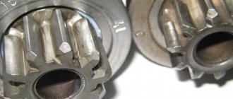
As you remember from the above, the retaining winding is so called because it is supposed to keep the starter drive gear engaged with the flywheel. In addition, at the same time, reliable contact is ensured in the switching unit. If the winding is burnt, then the magnetic field it creates will be very weak . Accordingly, the retractor will not have enough strength to hold the mechanism in the working position for the required period of time.
The retractor winding must work in such a way that the magnetic field strength is sufficient to confidently move the working rod and engage the starter drive gear with the engine flywheel. If there is an interturn short circuit in the winding, then it will work. But not effective enough. Finding out this same retraction force will be the second goal of this stage of checking the starter retractor relay.
To carry out the procedure described below you will need:
- Charged car battery (can be temporarily removed from the car).
- Three thick wires.
- Self-tapping screw.
- A piece of copper wire.
- Wooden surface.
Attention! The steps described below must be performed without delay. Before checking, re-read the algorithm several times and go through all the steps in your head. Carefully check whether you have connected everything correctly and go through the sequence of actions in your mind one more time. If you make a mistake at this stage, yawn, hesitate, you can injure yourself, ruin the working solenoid relay, or create an epic fireworks display with sparks.
Algorithm:
- Screw the screw into the wooden base.
- Secure the anchor (rod) of the solenoid relay to the self-tapping screw with wire.
- Connect the “plus” of the battery using a thick wire to the power contact of the relay without a jumper.
- With the second wire, separately connect the “plus” of the battery to the control contact.
- Press the retractor relay against the self-tapping screw so that the armature does not overcome the resistance of the spring, but goes slightly inside.
- Connect the negative of the battery to the power terminal with a jumper.
- If the armature is pulled inward with weak force, there is an interturn short circuit in the retracting winding .
- When the relay operates, try to pull the retractor back with moderate hand force.
- If you fail to pull the retractor, the retaining winding is working .
- If the armature easily came out of its seat and remained hanging on the screw, the holding winding is faulty (even if there is no break, there may be an interturn short circuit in it).
- Allow no more than 3 seconds for the entire check, after which de-energize the assembled circuit by disconnecting the negative terminal.
- If you didn’t manage to understand anything the first time, don’t rush to supply power to the circuit again. Wait 10 minutes for the coils of the solenoid relay to cool down after loading.
As mentioned earlier, the solenoid relay cannot be repaired. Therefore, if at one of the stages you find a break or an interturn short circuit, the part needs to be replaced.
Checking the switch node
The last step is to check the solenoid relay for faults in the switching power unit. Let us remind you that there may be either poor contact, or its absence at the right moment, or even sticking. The purpose of the test is to determine whether the starting current flows to the starter at the moment the solenoid relay is activated.
The algorithm is like this:
- Turn the multimeter into dialing mode.
- Connect one probe to any power contact of the solenoid relay.
- Connect the second probe to the second of the two power contacts.
- Fix the probes to free both hands for further manipulations (tie them with wire or clamp them with crocodile clips).
- If in this position the multimeter has already beeped, the switching unit is stuck .
- Install the anchor (or rod) of the retractor relay in its rightful place and push it in with force until it stops.
- The squeak of the multimeter at this moment indicates that the switching unit is working .
- If the device is silent, the switching unit is broken (no contact, burnt plates).
- If the multimeter does not beep, but shows a high resistance on the display, the contact in the switching unit is too poor (carbon deposits, oxide, scale).
In fact, there is nothing to repair if something happens. The solenoid relay is a non-separable part. However, some models can still be partially dismantled with a hammer, screwdriver and kind words. If you have steady hands, you can even clean the contacts and carefully put everything back to its original state.
Brief summary
To fully check the starter solenoid relay, it will have to be completely removed. Additionally, you will need a simple multimeter, a charged battery, wires, a self-tapping screw and a clear understanding of what is happening. Without confidence in what you are doing, it is highly not recommended to risk performing force tests on the solenoid relay. Limit yourself to checking the continuity with a multimeter and simply cleaning the assembly. If you are confident, you can check the solenoid relay 100%, as well as identify absolutely any of its possible breakdowns.