Array ( [DATE_ACTIVE_FROM] => 01/29/2021 04:38:00 [~DATE_ACTIVE_FROM] => 01/29/2021 04:38:00 [ID] => 511400389 [~ID] => 511400389 [NAME] => Cylinder head tightening order ZIL-130 [~NAME] => Order of tightening the cylinder head ZIL-130 [IBLOCK_ID] => 33 [~IBLOCK_ID] => 33 [IBLOCK_SECTION_ID] => [~IBLOCK_SECTION_ID] => [DETAIL_TEXT] => Order specified in the operating instructions tightening the ZIL-130 cylinder head is not an idle whim of the developers. Neglect of the requirements of technical regulations causes serious, sometimes irreparable malfunctions. Knowing this, qualified specialists involved in servicing internal combustion engines use in the repair process only information taken from reliable sources.
Design features of the internal combustion engine
The power unit installed on ZIL-130 trucks of various modifications is reliable and unpretentious. Features of the traditional layout for the sixties of the twentieth century are:
- V8 architecture with a 90° cylinder angle, ensuring convenient engine layout in the engine compartment.
- Cylinder block cast from gray ductile iron.
- The lower location of the camshaft is connected to the crankshaft by a transmission of two helical gears.
- Separate cylinder heads cast from AL4 aluminum alloy and hardened to a maximum hardness of HB 70 using hardening and aging techniques.
- Top valve arrangement. The opening force is transmitted to them through pushers and rocker arms mounted on shafts.
- A liquid cooling system that can quickly remove excess heat and maintain an optimal temperature for internal combustion engine operation even under high loads.
The order and tightening torque of the ZIL-130 cylinder head were determined during calculations and confirmed during field tests.
The listed technical solutions have proven themselves well in practice. The developers of the Likhachev plant managed to create a reliable and unpretentious power unit, the mileage of which, before major repairs, is 500 thousand km or more. But this does not mean that the engine, produced from 1962 to 2010, will tolerate frankly barbaric treatment. The procedure for tightening the ZIL-130 cylinder head must be followed to preserve engine life and achieve design characteristics.
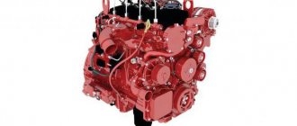
Engine structure ZIL 130
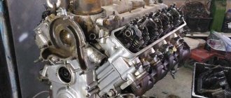
The ZIL-130 engine is a V-shaped, eight-cylinder, four-stroke, carburetor, liquid-cooled. The structure of the ZIL-130 engine is shown below. The ZIL-130 engine mount , its longitudinal and transverse sections are shown in Fig. 9-11.
The cylinder block of the ZIL-130 engine is made of cast iron, with insertable wet liners made of gray cast iron, with an acid-resistant insert in the upper part. To seal the upper part of the liner, the sleeve collar is clamped between the block and the block head with an asbestos steel gasket, the lower part is sealed with two rubber rings. cylinder heads are made of aluminum alloy, with plug-in seats and valve guides. Gaskets made of asbestos steel are installed between the block and the heads. Each cylinder head is attached to the cylinder block with seventeen bolts. The holes in the cylinder block for the bolts are counterseen. It should be remembered that the four bolts securing the rocker arm axis are also the bolts securing the cylinder head of the ZIL-130 engine and are included in the seventeen bolts indicated above.
Rice. 9. ZIL-130 engine mount: a - front support; b — rear support; 1 — protective cap; 2 — front support mounting bolt; 3 — front support bracket; 4 and 12—engine mounting bolts; 5 — front cover of the cylinder block; 6 — upper cushion of the front support; 7 — lower cushion of the front support; 8 — washer; 9 — spacer sleeve; 10 — frame cross member; 11 — clutch housing; 13 — rear support mounting bolt; 14 - cover; 15 — rear support bracket; 16 - shoe; 17 — rear support cushion; 18 — adjusting gasket.
The bolts securing the heads to the block must be tightened with a special torque wrench, which allows you to control the tightening torque, since the aluminum block head, when heated, increases in height more than the steel bolts securing it. When the engine warms up, the tightening of the block heads increases, and when cooled, it decreases, so the head bolts must be tightened on a cold ZIL-130 engine. The tightening torque should be 90–110 N • m (9–11 kgf • m), and at an engine temperature of about 0 ° C, the tightening torque of the bolts should be closer to the lower limit of 90 N • m (9 kgf • m), and at a temperature from + 20 to + 25° C - closer to the upper limit of 110 N • m (11 kgf • m). It is prohibited to tighten the bolts securing the cylinder heads of the ZIL-130 engine when the engine temperature is below 0° C. In this case, you should first warm up the engine and then tighten the bolts. Simultaneously with tightening the cylinder head bolts, it is necessary to tighten the exhaust gas pipeline bolts. After tightening the cylinder head bolts, it is necessary to check and, if necessary, adjust the clearances in the valve mechanism. To ensure complete contact of the head planes with the ZIL-130 engine block, it is necessary to follow the bolt tightening order indicated in Fig. 12. Tighten the cylinder head bolts evenly in two steps. First tighten all the bolts, and then additionally tighten bolts 1, 2, 3, 4 and 5. When changing gaskets, all water holes in the cylinder heads and cylinder block, as well as the combustion chamber, must be cleared of deposits. The cylinder head cover gasket should be installed with the grooved surface facing the cylinder head cover. The nuts securing the engine head cover of the ZIL-130 car must be tightened evenly; the tightening torque should be 5-6 N • m (0.5-0.6 kgf • m).
Current:
Front and rear suspension ZIL-130
Procedure for disassembling the power steering pump
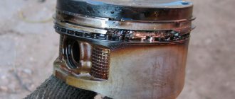
Pistons ZIL-130
Possible breakdowns
When heated to operating temperature, the aluminum alloy from which the cylinder heads of the V-shaped eight-cylinder engine used in popular truck models expands. If the order and tightening torque of the ZIL-130 cylinder head are not followed, this may cause the head gasket to burn out, cracks to form in the cylinder walls, lubrication channels, and cooling jackets. As a result, prerequisites arise for coolant leakage and its ingress:
- Cylinders. In small quantities, water or alcohols contained in antifreeze present in the fuel mixture are not capable of causing harm to the engine. But an increase in their concentration causes severe detonation, leading to burnout of valves and components of the cylinder-piston group.
- Lubrication systems. When mixing lubricant and coolant, an emulsion the color of coffee with milk is formed, which does not have the consistency necessary for the operation of the internal combustion engine. Oil pressure drops, which causes destruction of mating parts that require a constant supply of lubricants.
The opposite is also possible. In some cases, exhaust gases or engine oil enter the cooling system, impairing heat dissipation, and the engine overheats. To prevent this from happening, it is necessary to follow the procedure for tightening the ZIL-130 head, tightening the bolts with the force specified in the technical specifications.
Sequence of actions and necessary tools
Before starting work, you should make sure that the mating surfaces are free of contamination. If parts have previously been in use, they should be cleaned using special tools, solvents and detergents. The head must be checked for flatness and, if necessary, ground. After that:
- Check the integrity of the threads in the holes of the block.
- Install the head gasket.
- Install the unit in its original place.
- Install the rocker shaft and washers.
- They attach the fasteners.
- Observing the procedure for tightening the ZIL-130 cylinder head, tighten the bolts with a torque of 90 - 110 Nm.
To develop the necessary force without damaging critical parts, it is recommended to use:
- A torque wrench with a long, at least 1 meter, wrench. As an option - a wrench equipped with a torque attachment.
- An appropriately sized hex socket socket made of chrome vanadium steel. When using polygon keys made of steel hardened by work hardening, you risk licking off the edges on the bolts and damaging your hands.
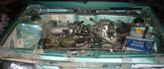
Pull smoothly, ensuring uniform tightening torque of the ZIL-130 engine. Jerks and shock loads are unacceptable! It is advisable to perform all operations by mounting the motor on a special stand. But it is possible, if there is no other way out, to carry out repairs without removing the power unit from the car. For convenience, it makes sense to remove the hood cover.
Checking the tightness of the cylinder head bolts and nuts
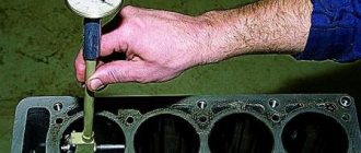
It is recommended to check the tightness of the cylinder head bolts and nuts using a torque wrench (Fig. 1). The tightening torque should be within 10-12 kgm.
Tightening the cylinder head bolts and nuts should be done in a certain sequence (Fig. 2) on a cold engine.
The gaps between the valves and pushers are checked when knocking occurs in the valves, after which they are adjusted. It is recommended to adjust the valve clearances separately for each cylinder in accordance with the firing order in the cylinders (1-5-3-6-2-4). The clearance between the tappet and the valve for intake and exhaust valves should be 0.20-0.25 mm for engines with a compression ratio of 6.2 and 0.23-0.28 mm for engines with a compression ratio of 6.5. Before adjusting the gaps, it is necessary to: disconnect the fuel line from the fuel pump to the carburetor, which makes access to the valve boxes difficult;
disconnect the engine crankcase ventilation pipe and move it to the side;
Unscrew the bolts securing the valve box covers and remove the covers with gaskets. Remove valve box covers carefully, taking care not to damage the cork gaskets.
Adjusting the clearances of the intake and exhaust valves should begin with the first cylinder, for which you should install the piston in. m.t. during the compression stroke using an adjusting pin or according to the flywheel mark.
When installing the piston of the first cylinder in c. M. Unscrew the installation pin 1 (Fig. 3, a) and insert it into the same hole with the other end, then turn the crankshaft and hold it until the pin coincides with the hole on the camshaft gear. Having finished installing the piston of the first cylinder in c. m.t., screw the installation pin into place.
When installing the piston of the first cylinder in c. m.t. according to the flywheel mark, you need to open the inspection hatch on the clutch housing so that the flywheel rim is visible, turn the engine crankshaft with the handle and install the piston of the first cylinder in. m.t. so that risk 3 (Fig. 3, b) c. m.t. on the flywheel coincided with mark 2 on the clutch housing. After installing the piston of the first cylinder in c. M. T. lower the inspection hatch cover and secure it.
Check the size of the gap between the adjusting bolts of the pushers and the valve stems using a feeler gauge (Fig. 4, a). If the gaps are outside the specified limits, they should be adjusted. The adjustment is made as follows:
holding the pusher by the flat with one wrench, use another wrench to loosen the lock nut of the pusher adjusting bolt;
While continuing to hold the pusher, turn the pusher adjusting bolt until the required clearance is obtained;
holding the pusher adjustment bolt with one key and the pusher with the other key, tighten the locknut with the third key (Fig. 4, b).
After adjusting the valves of the first cylinder, it is necessary to adjust the remaining valves in the same way and reinstall the engine components removed before adjustment.
Start the engine and listen to its operation. A warmed-up engine should operate without valve knocking, “sneezing” in the carburetor and “shots” in the muffler.
On this topic:
Second maintenance (TO-2)
Starting heater
Centrifugal oil filters
The procedure for tightening the ZIL-130 head
If you look from above, they start tightening the bolts from the center, moving counterclockwise in a diverging spiral. For clarity, the procedure for tightening the ZIL-130 cylinder head is shown in the figure below.
This sequence allows for a tight fit of the mating surfaces and reduces the risk of residual stresses in the structure. It is recommended to loosen the bolts in the same order when dismantling the unit.
The order and tightening torque of the ZIL-130 cylinder head is the same for both cylinder heads, mirrored on the V-shaped engine. Only after all these operations are completed, do they begin to install the intake manifold, the so-called spider, and additional equipment.
Note to motorists
In conclusion, here are some practical tips that are useful for both novice car mechanics and experienced equipment repair specialists:
- Do not try to learn the procedure for tightening the ZIL-130 block head by heart. Mistakes happen to everyone, even those with a good memory. It is better to keep the necessary information at hand and check the data before starting work.
- Do not use pneumatic or electric impact wrenches when repairing the engine. When operating such equipment, significant shock loads are created.
- Do not exceed the tightening torque of the ZIL-130 head specified in the instructions. You may damage the part or strip the threads in the block.
If you do not have the necessary tools at your disposal, use the services of specially equipped workshops.
[~DETAIL_TEXT] =>
The procedure for tightening the ZIL-130 cylinder head specified in the operating instructions is not an idle whim of the developers. Neglecting the requirements of technical regulations causes serious, sometimes irreparable, malfunctions. Knowing this, qualified specialists involved in servicing internal combustion engines use only information taken from reliable sources during the repair process.
Design features of the internal combustion engine
The power unit installed on ZIL-130 trucks of various modifications is reliable and unpretentious. Features of the traditional layout for the sixties of the twentieth century are:
- V8 architecture with a 90° cylinder angle, ensuring convenient engine layout in the engine compartment.
- Cylinder block cast from gray ductile iron.
- The lower location of the camshaft is connected to the crankshaft by a transmission of two helical gears.
- Separate cylinder heads cast from AL4 aluminum alloy and hardened to a maximum hardness of HB 70 using hardening and aging techniques.
- Top valve arrangement. The opening force is transmitted to them through pushers and rocker arms mounted on shafts.
- A liquid cooling system that can quickly remove excess heat and maintain an optimal temperature for internal combustion engine operation even under high loads.
The order and tightening torque of the ZIL-130 cylinder head were determined during calculations and confirmed during field tests.
The listed technical solutions have proven themselves well in practice. The developers of the Likhachev plant managed to create a reliable and unpretentious power unit, the mileage of which, before major repairs, is 500 thousand km or more. But this does not mean that the engine, produced from 1962 to 2010, will tolerate frankly barbaric treatment. The procedure for tightening the ZIL-130 cylinder head must be followed to preserve engine life and achieve design characteristics.
Spare parts for Ural, Kraz, MAZ, Kamaz trucks. Engine parts YaMZ-236, YaMZ-238
__________________________________________________________________________
__________________________________________________________________________
Cylinder head and valves ZIL-130
___________________________________________________________________________
Checking the fastening of the ZIL-130 cylinder head The ZIL-130 internal combustion engine is equipped with cylinder heads made of aluminum alloy with steel-asbestos gaskets between the heads and the block. Cylinder heads must always be secured with a specified bolt torque. If the cylinder head bolts are incompletely or incorrectly tightened, the tightness of the combustion chamber is compromised and gas breakthrough is possible in those places of the gasket where it is loosely clamped. At the same time, the engine experiences interruptions in operation, unstable operation at low speeds, and starting after the engine is stopped worsens. In addition, if the gasket is damaged, the cooling system fluid enters the cylinders, causing corrosion of the cylinder bore. These reasons lead to loss of power or termination of operation of the ZIL-130 internal combustion engine. Each cylinder head is attached to the engine block with 17 bolts. The bolts should be tightened on a cold engine in two steps - preliminary and final. The final tightening is necessary with a torque wrench, which allows you to control the tightening torque, which should be 7-9 kgm. If you don’t have a torque wrench, you can tighten it with a regular wrench with one hand without jerking. It must be borne in mind that cylinder heads made of aluminum alloy expand when the engine warms up, and therefore the tightening of the block bolts increases; When the engine cools, the opposite occurs. Therefore, at an internal combustion engine temperature of plus 20-25°C, the bolt tightening torque should be closer to the upper limit of 9 kgm, and at an internal combustion engine temperature below minus 5°C, the bolt tightening torque should be closer to the lower limit of 7 kgm. When the ZIL-130 engine is fully warmed up, the tightening of the cylinder head automatically increases to the required limit. Please note that the four rocker arm axle bolts are also the cylinder head bolts; they should also be tightened. If the heads are tightened, you need to check for possible changes in the gaps between the valves and rocker arms. When changing gaskets, it is necessary to clean all the holes in the cooling jacket in the heads and in the cylinder block. Assembling the ZIL-130 cylinder head with valves. For assembly, use the same stand as for disassembly. The ZIL-130 cylinder head is mounted on a stand and the holes in the bushings and valve seats are blown out with compressed air.
Before installation, the intake and exhaust valve stems and the cylinder head guide bushings are lubricated with oil. The valves should turn smoothly and move in the guide bushings. In case of jamming, select another valve.
Valve spring washers are put on the intake valve bushings, directing them with a flat surface to the cylinder head, and the valve rotation mechanism is placed on the exhaust valve bushings. Then rubber cuffs are put on the intake valves. When installing springs on valves, pay attention to the fact that the coils are located with a smaller pitch towards the cylinder head. Having placed the valve spring plates on the ZIL-130 valve stems, turn the handle of the air distribution valve; in this case, the pressure device of the stand simultaneously compresses all the valve springs. Lubricated with grease, the crackers are installed in the grooves of the valve stems and the pressure device of the stand is raised to its original position. In this case, it is necessary to ensure that the valve crackers fit into the conical holes of the valve spring retainers. Rotating the cylinder head to a convenient position, screw the studs into the holes of the upper plane, the contact plane of the intake and exhaust pipelines. Adjusting nuts and screws are screwed into the threaded holes of the rocker arms so that their heads are 5-6 mm away from the rocker arms. Having installed a cotter pin in the holes of the rocker arm axle, put the oil drain chute bracket, washers, valve rocker arm, strut assembly with bushing, spacer spring, etc. on the axle. Place the axle assembly with the rocker arms in the device, compress the spacer springs, insert the cotter pin into the axle hole and install the oil drain chute on the brackets. ICE valves ZIL-130 Valves ZIL-130 are upper, located in the cylinder head in one row, inclined to the cylinder axis, driven from the camshaft through rods, pushers and rocker arms. The valves are made of heat-resistant steel; the angle of the working chamfer of the intake valve seat is 30°, exhaust 45°; The exhaust valve stem has a hole filled with sodium.
To increase their service life, the exhaust valves are forcibly turned during engine operation by a special mechanism. If knocking occurs in the valve mechanism, it is necessary to check and, if necessary, adjust the gaps between the valves and rocker arms, which should be within 0.25-0.3 mm (for intake and exhaust valves). Adjustment of the clearances in the valve mechanism of the ZIL-130 internal combustion engine is carried out on a cold engine using an adjusting screw and locknut located in the short arm of the rocker arm.
To adjust the clearance in the valve mechanism, you need to set the piston of the first cylinder to the top dead center (TDC) of the compression stroke. In this case, the hole on the crankshaft pulley should be located under the “TDC” mark on the ignition timing indicator located on the crankshaft maximum speed limiter sensor. In this position, the clearances of the following valves of the ZIL-130 internal combustion engine are adjusted: - intake and exhaust cylinder 1 - exhaust cylinder 2, intake cylinder 3 - exhaust cylinder 4 - exhaust 5 - intake 7 - intake 8 - g Adjustment of ZIL-130 valves The temperature gap between the valve stem and the toe of the rocker arm gradually changes during operation due to wear of the mating parts of the ZIL-130 timing mechanism and leads to a violation of the adjustment. Therefore, clearances must be periodically checked and adjusted. Increased clearance between the intake valve stem and rocker arm nose reduces valve opening time. This impairs the filling of the cylinder with the combustible mixture, makes it difficult to start the engine, and during its operation leads to a drop in power. An increased exhaust valve clearance leads to poor removal of exhaust gases from the cylinder; engine operation is accompanied by a characteristic metallic knock. Reduced clearance between the valve stem and the toe of the rocker arm leads to a loose fit of the valves in the seat. At the same time, the ZIL-130 internal combustion engine loses compression and overheats, and its power decreases. With a small intake valve clearance, the working mixture during the compression stroke is partially pushed into the intake manifold and then into the carburetor. This phenomenon causes a decrease in the amount of working mixture, lowers the pressure in the cylinder and leads to a drop in engine power. Another sign of a loose intake valve is popping noises in the carburetor, since some of the flammable gases, entering the intake manifold during the working stroke and then into the carburetor, causes ignition of the combustible mixture, which is dangerous in terms of fire. When the clearance at the ZIL-130 exhaust valve is small, this also leads to a drop in power, since during the compression stroke part of the working mixture is removed into the exhaust pipe and then into the muffler. In this case, due to the combustion of the working mixture in the exhaust pipe and in the muffler, popping noises will be heard, accompanied by black smoke coming out of the muffler. Running the engine for a long time with poor valve clearances can lead to premature burning and wear of valve heads, valve seats, warping of valve stems, and wear of the cams. Adjusting valve clearances on a cold ZIL-130 engine at a temperature of 15-20°C in two ways. In the first method, the valves are adjusted separately for each cylinder.
Raise the engine hood, unscrew the nine nuts securing the valve covers with a wrench and remove them, while the cover gaskets do not need to be removed. Then install the piston of the first cylinder in c. m.t. (compression stroke) using an adjusting gear pointer, for which the crankshaft is turned until the mark on the crankshaft pulley aligns with the TDC mark on the pointer (at the end of the second revolution of the crankshaft). When installing the piston in. The radiator lining prevents the alignment of the indicator marks and the crankshaft pulley from being determined. Therefore, it is recommended to unscrew the spark plug of the first cylinder and remove the distributor cap, which allows you to accurately determine the installation of the piston in the cylinder. m.t. (compression stroke). At the same time, the piston, approaching the c. m.t., will push air out of the cylinder through the spark plug hole, which can be easily felt with a finger applied to the hole; when the piston is in. m.t., then the distributor rotor electrode will be located opposite the terminal of the first cylinder. In this case, both valves, inlet and outlet, of the first cylinder will be closed, and the largest gap will form between the valve stem and the toe of the rocker arm, which is measured with a feeler gauge and, if necessary, adjusted. To adjust the clearance of the ZIL-130 valves, you need to hold the adjustment screw with a screwdriver, loosen the lock nut with a 14X12 mm wrench, then take the feeler gauge with one hand, place it in the gap between the valve stem and the toe of the rocker arm, and with the other hand take the screwdriver and rotate the adjustment screw, setting the required gap, then leave the feeler gauge in the gap and secure the adjusting screw with a lock nut using a wrench and a screwdriver. After adjustment, the gap should be 0.25-0.30 mm for the intake and exhaust valves, and the 0.25 mm feeler gauge should pass freely through the gap, and the 0.30 mm feeler gauge should not pass through it. To adjust the gap in the ZIL-130 valves of the remaining seven cylinders, you need to turn the crankshaft with a handle, and adjust the gaps sequentially according to the operating order of the cylinders 1-5-4-2-6-3-7-8. If the valves are adjusted on an engine removed from the car, or with the radiator removed from the car, then in order to rotate the crankshaft 4 turns, you need to put chalk marks on the crankshaft pulley, placing them at an angle of 90° with the piston of the first cylinder in the crank position. m.t. (compression stroke). The clearances of the remaining valves are adjusted after turning the crankshaft 360° (full rotation). Prolonged operation of the engine with incorrect clearances can lead to premature wear of valve mechanism parts, burning of valves, wear of rocker arms, bearing surfaces of pushrods and camshaft cams. During any disassembly of the ZIL-130 internal combustion engine, which has traveled more than 70 thousand km, it is necessary to check the condition of the return springs and balls of the mechanism for turning the exhaust valve.
If signs of wear are found on the coils of the spring, the spring must be turned with the worn area down. When assembling the mechanism for turning the valve, you need to pay attention to the correct installation of balls and springs; the springs must be located behind the ball relative to the selected direction of rotation. Valve pushers are steel, hollow. To increase the reliability of the cam-pusher pair, special cast iron is melted onto the end of the pusher. There are holes drilled in the bottom of the pusher for lubrication. The intake pipeline is made of aluminum alloy, common to both rows of cylinders, located between the cylinder heads and equipped with a liquid cavity for heating the mixture. The tightening torque of the nuts securing the intake manifold to the cylinder head should be within 15-20 Nm (1.5-2 kg/cm). The nuts must be tightened evenly, sequentially, crosswise. Exhaust gas pipelines are cast iron, one G on each side of the block. Cover of the timing gears of the ZIL-130 timing gear The cover of the ZIL-130 timing gears is made of AL-4 aluminum alloy. It not only covers the timing gears, but is also the front engine support, which bears significant loads. The cover of the timing gears of the ZIL-130 gas distribution mechanism is rejected if there are chips. Cracks on the surface of the cover, passing close to the oil seal holes and the crankshaft maximum speed limit sensor, are welded. Having secured the lid in a bench vice, drill the ends of the crack and use a grinding wheel to process the crack to a depth of 2-3 mm at an angle of 90°.
The cover is heated in an electric oven to a temperature of 160-190 ° C and the surface prepared for welding is thoroughly cleaned with a metal brush. After cleaning the welded surface with a metal brush, in order to avoid corrosion from slag residues, the lid is washed in water at a temperature of 40-50 ° C. The seam should be smooth, without cavities and slag inclusions, the seam height is recommended no more than 0.5-1.0 mm . Cracks on the surface of the cover in places that bear minor loads are sealed with epoxy paste. An oil seal hole that is worn out beyond the acceptable size is fused, having previously bored it out on a lathe. To secure the ZIL-130 timing gear cover on the machine, use a device consisting of a faceplate to which a support plate is bolted. The timing gear cover is installed on the pins of the faceplate support plate and secured with clamps. The oil seal hole with a diameter of 93+0.1 mm is bored “as clean”, but no more than a diameter of 95.0 mm to a depth of 10.0+0.5 mm. For surfacing the oil seal hole of the timing gear cover, use the device shown in Fig. 13. The part is placed on two fingers and rotated to any convenient position during the welding process. After surfacing, the holes are cleaned and the quality of the weld is checked. The seam must be smooth, without cavities and slag inclusions. A hole for the bushings that is worn out beyond the acceptable size is repaired by drilling out the hole in the timing gear cover to a diameter of 19.60. A bushing of repair size is pressed into the restored hole and deployed. Rice. 13. Device for surfacing the oil seal hole in the timing gear cover ZIL-130 1 - stand; 2 — retainer ball; 3 — clamp spring; 4 - plug; 5—flange; 6 - finger; 7 - timing gear cover The fastening bolts of the gear cover of the ZIL-130 gas distribution mechanism carry significant loads, and therefore the surfaces of the cover flange under the head of the bolts wear out. The worn surface of the cover flange is machined “as clean”, maintaining the height of the bosses at least 11.0 mm. If the amount of wear on the surface of the cover flange is significant and it is not possible to ensure a boss height of more than 11.0 mm during machining, the worn flange is welded up to 14 mm. If no more than two threads break, thread M6 class. 2 in the mounting hole of the crankshaft maximum speed limit sensor is driven with a tap. If a thread breaks, more than two threads are cut to a repair size. To do this, the timing gear cover is fixed on the drilling machine table, using the mating plane as the base surface, and the worn threaded hole is drilled out to a diameter of 6.7 mm to a depth of 21.0 mm. An M8 thread is cut into the drilled hole. 2 repair sizes to a depth of 16.0 mm. When warping exceeds the permissible size, the mating plane of the timing gear cover of the ZIL-130 timing mechanism is milled “as cleanly” on a vertical milling machine. The thickness of the cover flange after processing must be at least 6.3 mm. When checking the machining accuracy, a 0.02 mm thick feeler gauge should not pass between the test plate and the mating plane of the timing gear cover.
_________________________________________________________________________
_________________________________________________________________________
_________________________________________________________________________
- Cardan shafts and power take-off Ural-4320
- Transmission gearbox Ural-4320
- Bridges Ural-4320
- Transfer case Ural-4320
- Steering Ural-4320
- Truck cranes and cranes based on trucks
_________________________________________________________________________
_________________________________________________________________________
- Cylinder block and cylinder head YaMZ-236 HE2, YaMZ-236 BE2
- Checking and adjusting YaMZ-236
- Power system and lubrication system YaMZ-236
- Driven and driven clutch discs YaMZ-236, 238
- Cooling and lubrication systems YaMZ-238
- Fuel injection pump YaMZ-238
_________________________________________________________________________
- Kamaz diesel engine
- Repair and adjustment of Kamaz power steering
- Kamaz-152 gearbox with divider
- Gearbox parts for Kamaz-5320 gearbox
- Kamaz transfer case and driveshafts
- Kamaz gearbox repair
- Clutch KamAZ-5320
- Construction of Kamaz-4310 drive axles
- Power steering MAZ-5551, 5549, 5335, 5336, 5337
- Front axle and steering rods MAZ-5551, 5549, 5335, 5336, 5337
- Clutch adjustment MAZ-5551, 5549, 5335, 5336, 5337
- Adjustment and repair of gearboxes MAZ-5551, 5549, 5335, 5336, 5337
- Repair and maintenance of the rear axle MAZ-5551, 5549, 5335, 5336, 5337
- Front axle parts and steering rods MAZ-5516, 5440
- Steering Maz-5516, 5440
- Details of driving axles Maz-5516, 5440
- Clutch device ZIL-130
- Repair of ZIL-130 gearbox
- Repair of rear axle ZIL-130
- Basic parts of the ZIL-130 engine
- Transfer case and power take-off ZIL-131
- Drive axles ZIL-131
- Steering ZIL-131
- Maintenance of ZIL-645 engine parts
Possible breakdowns
When heated to operating temperature, the aluminum alloy from which the cylinder heads of the V-shaped eight-cylinder engine used in popular truck models expands. If the order and tightening torque of the ZIL-130 cylinder head are not followed, this may cause the head gasket to burn out, cracks to form in the cylinder walls, lubrication channels, and cooling jackets. As a result, prerequisites arise for coolant leakage and its ingress:
- Cylinders. In small quantities, water or alcohols contained in antifreeze present in the fuel mixture are not capable of causing harm to the engine. But an increase in their concentration causes severe detonation, leading to burnout of valves and components of the cylinder-piston group.
- Lubrication systems. When mixing lubricant and coolant, an emulsion the color of coffee with milk is formed, which does not have the consistency necessary for the operation of the internal combustion engine. Oil pressure drops, which causes destruction of mating parts that require a constant supply of lubricants.
The opposite is also possible. In some cases, exhaust gases or engine oil enter the cooling system, impairing heat dissipation, and the engine overheats. To prevent this from happening, it is necessary to follow the procedure for tightening the ZIL-130 head, tightening the bolts with the force specified in the technical specifications.
Installing pistons with connecting rods into engine cylinders
To install pistons with connecting rods, turn the cylinder block, install it vertically on the stand, with the front part up, and insert the pistons into the cylinders respectively: 1st - 5th, 2nd - 6th, 3rd - 7th and 4th-8th, placing the connecting rod bearings in pairs on the corresponding crankpins of the crankshaft.
Sequentially, one by one, take the piston and connecting rod assembly, thoroughly wipe the bed under the liners in the lower head of the connecting rod with a napkin, unscrew the nuts and remove the connecting rod cover.
When installing a connecting rod with a piston, it is necessary to put brass or copper tips on the connecting rod bolts to protect the cylinder liner mirror from damage.
Check and blow out the hole in the lower head of the connecting rod, which serves to spray lubricant onto the cylinder walls, insert the liners into the connecting rod and into the cover. Wipe the upper connecting rod bearings, piston, cylinder liners and connecting rod journals with a napkin. Lubricate the surface of the connecting rod bearing, piston, piston rings and cylinder liners with clean engine oil.
Insert the piston with connecting rod into the cylinder, pointing the mark on the piston bottom forward. Place the device on the piston from the skirt side (Fig. 1, a) and compress the piston rings. The rings should compress freely. Compression of the piston rings when installing the piston into the cylinder can be done using a belt device (Fig. 1, b) model 2477. Moving the piston along the cylinder using a wooden mandrel, bring the connecting rod bearing to the crankshaft journal. Lubricate the shaft journal with oil and pull the lower head towards it. Remove the safety tips from the connecting rod bolts, replace the bottom cover of the connecting rod and secure it with the connecting rod bolts using a socket wrench.
Carry out the same operations when installing the remaining pistons into the cylinders.
Check the total gap between the ends of the connecting rod bearings and the end cheek of the crankshaft using a feeler gauge (Fig. 2). The gap should be 0.30-0.56 mm.
Make final tightening of the connecting rod bolt nuts using a torque wrench. The tightening torque of the nuts should be in the range of 7.0–8.0 kgm. When tightening the nuts, you need to place their slots under the cotter pin. Bring the nuts until the nearest slot coincides with the hole for the cotter pin in the bolt only in the direction of increasing tightening.
After tightening the main and connecting rod bearings, check the crankshaft rotation. The torque for turning the shaft with correctly selected radial clearances in the bearings should be no more than 10 kgm. Having finished checking the tightness of the connecting rod bearings, you need to tighten the nuts of the connecting rod bolts by bending both ends of the cotter pin.
On this topic:
ZIL 131 overseas colleagues
Driving ZIL-131 on the site at a driving school
Piston-connecting rod set
Sequence of actions and necessary tools
Before starting work, you should make sure that the mating surfaces are free of contamination. If parts have previously been in use, they should be cleaned using special tools, solvents and detergents. The head must be checked for flatness and, if necessary, ground. After that:
- Check the integrity of the threads in the holes of the block.
- Install the head gasket.
- Install the unit in its original place.
- Install the rocker shaft and washers.
- They attach the fasteners.
- Observing the procedure for tightening the ZIL-130 cylinder head, tighten the bolts with a torque of 90 - 110 Nm.
To develop the necessary force without damaging critical parts, it is recommended to use:
- A torque wrench with a long, at least 1 meter, wrench. As an option - a wrench equipped with a torque attachment.
- An appropriately sized hex socket socket made of chrome vanadium steel. When using polygon keys made of steel hardened by work hardening, you risk licking off the edges on the bolts and damaging your hands.
Pull smoothly, ensuring uniform tightening torque of the ZIL-130 engine. Jerks and shock loads are unacceptable! It is advisable to perform all operations by mounting the motor on a special stand. But it is possible, if there is no other way out, to carry out repairs without removing the power unit from the car. For convenience, it makes sense to remove the hood cover.
Timing gear cover ZIL-130
Timing device of the ZIL-130 engine
The timing gears in the timing belt are covered with a cover, which in parallel serves as a support for the ZIL-130 motor. The main requirement here is the absence of chips. Otherwise, the lid is replaced, while small cracks are welded, making an even seam 0.5-1 mm high, without inclusions of slag and the presence of shells.
If cracks are found in places where there is no significant load, it is enough to seal the seams with epoxy. The erased stuffing box holes are fused after preliminary boring on the machine.
Having detected wear on the cover flange, they make deposits, increasing the height of the bosses to a parameter of 1.4 cm. They control the thickness, maintaining a parameter of 0.63 cm. Having completed all the necessary actions, check the gap between the control plate and the timing gear cover at 0, 02 mm.
Related video: Valve adjustment - ZIL 130 engine repair
Publications on the topic
Adjusting the valves of the YaMZ 238 engine
Features of adjusting valves GAZ-53
Performing adjustment of valves UMZ 4216
The procedure for tightening the ZIL-130 head
If you look from above, they start tightening the bolts from the center, moving counterclockwise in a diverging spiral. For clarity, the procedure for tightening the ZIL-130 cylinder head is shown in the figure below.
This sequence allows for a tight fit of the mating surfaces and reduces the risk of residual stresses in the structure. It is recommended to loosen the bolts in the same order when dismantling the unit.
The order and tightening torque of the ZIL-130 cylinder head is the same for both cylinder heads, mirrored on the V-shaped engine. Only after all these operations are completed, do they begin to install the intake manifold, the so-called spider, and additional equipment.