Good afternoon everyone. In today's article we are looking at a typical problem - the oil pressure in the ZMZ 406 engine has disappeared. Unfortunately, this is a fairly common problem and there are quite a few typical causes. In the article we will analyze all the reasons and how they manifest themselves.
Let's start with a description of the design of the ZMZ 406 lubrication system:
The oil pump is driven by the intermediate shaft through a hexagon. The oil pump has a pressure relief valve that releases excess oil pressure back into the crankcase. From the oil pump, oil is supplied through a filter to the main oil line, from which the crankshaft journals and timing drive intermediate shaft bushings are lubricated. Also from the main line there is a channel to the cylinder head and to the hydraulic tensioners. In turn, 2 oil channels are drilled into the cylinder head parallel to the camshafts. Through these channels, oil is supplied to each camshaft journal and to each of the 16 hydraulic compensators.
The most problematic places in the lubrication system are the pressure relief valve, intermediate shaft bushings and hydraulic chain tensioners, but first things first...
The oil pressure in the ZMZ 406 suddenly disappeared.
There are only two reasons in this case - the oil pump pressure reducing valve is stuck in the open position. It looks like this:
This usually happens due to dirt getting under the pressure relief valve. Even the slightest crumb jams the valve and it does not close completely.
The second typical reason is a breakdown of the oil pump drive.
The drive looks like this:
It should be noted that these two malfunctions occur extremely rarely and they occur when the oil change interval is not observed and when operating on oil that is not suitable for the climate.
The oil pressure in the engine dropped gradually.
This is the most common problem, it is associated with natural wear, frequency of maintenance and design errors....
The most common cause is the oil filter.
While operating the gazelle (2705), I changed the filter every 5,000 km, and changed the oil every 10,000 km. The reason is that when running on gasoline, the oil quickly darkens and a lot of dirt forms in it, which clogs the filter. When operating on gas, this problem does not occur!
The second most popular reason is gasoline getting into the fuel.
Basically, the share of carburetor versions of the 406 engine is fair (if the gas pump membrane ruptures, gasoline inevitably gets into the oil), but on an injection engine with a running injector this is a completely possible scenario.
The third reason is wear and tear.
Due to wear, all gaps in friction pairs gradually increase.
- The main place where pressure is lost is the intermediate shaft. Many people do not change the intermediate shaft support bushings even during a major overhaul, but it is in these bushings that most of the pressure is lost.
- The second most popular place is worn hydraulic chain tensioners.
- Third place is cylinder head wear and camshaft wear. The fact is that on the 406 engine, the camshaft beds are located in the body of the cylinder head and with the slightest “shift” of the plane, bed wear increases significantly - the result is a loss of pressure. When the shaft itself wears out, the gap in the friction pair increases and pressure is also lost.
- The fourth place is wear of the oil pump. If the pump wears out, it will not pump enough oil into the engine lubrication system and there will be no oil pressure. You can combat this by overhauling the pump and removing its planes, or by replacing the oil pump assembly with an oil pump from ZMZ 514 (it is for a diesel engine and has increased performance).
- Fifth place - hydraulic valve clearance compensators, compensators in the cylinder head 16 (according to the number of valves) and at high mileage their beds are also subject to wear, but the service life of the compensator beds, as a rule, exceeds the service life of the cylinder head.
The fourth reason is the oil bypass valve springs.
A bypass valve is installed on the oil pump housing; it opens when the oil pressure is high. The fact is that over time, the valve springs weaken and part of the oil pressure is lost on this valve. There is nothing wrong if you put a couple of washers under the valve spring when rebuilding the pump.
About the oil cooler.
Some modifications of the ZMZ 406 have a radiator installed to cool the oil, but in reality this design is practically not used since it reduces the pressure of the already diluted oil and has low-quality valves that constantly run. The oil cooler is implemented relatively competently on the ZMZ 405 (a thermal valve is used), but even there its effectiveness is questionable. In most cases, it is advisable to turn off the oil cooler and use a more thermally stable oil (tested from personal operating experience with Gas 2705 with a mileage of 470,000 km).
Ways to increase oil pressure in the ZMZ 406 engine during operation.
- More frequent oil filter replacement.
- Replacing the oil pump with a pump from ZMZ 514 part number 514 .1011010
- Disabling the oil cooler or replacing it with a heat exchanger.
- Replacing the oil with a thicker and higher quality one, it is the viscosity at high temperatures that is important.
- Place 2-3 washers under the oil bypass valve spring
Ways to increase oil pressure during major repairs.
Be sure to re-bush the intermediate shaft and rotate the bushings correctly.
Install jets in the lubrication system.
The fact is that there are several places in the engine where a lot of pressure is lost, and to increase the service life of the engine during a major overhaul, it makes sense to plug some channels in the lubrication system with jets from the carburetor! The best option turned out to be jets drilled with a 2 mm drill.
So, here are these places and options for their liquidization:
Oil pump shaft lubrication hole
Hydraulic chain tensioners (upper and lower)
That's all for me. I hope that the problem of missing oil pressure in the 406 engine will never bother you again.
The condition of the oil pump 406.1011010-03 of the ZMZ-40524 engine of Gazelle and Sable cars can be most fully assessed by checking it on a special stand.
If the ZMZ-40524 engine system is low, a possible cause of which could be a malfunction of the oil pump, the pump must be disassembled and the technical condition of its parts checked. When checking the pressure reducing valve, make sure that its plunger moves freely in the opening of the inlet pipe, without jamming, and that the spring is in good condition.
Then check for defects on the working surface of the plunger and the hole in the pump inlet pipe, which can lead to a drop in pressure in the lubrication system and jamming of the plunger. If necessary, remove small defects on the surface of the inlet pipe opening by grinding with fine-grained sandpaper, avoiding increasing the diameter. Wear of the hole in the inlet pipe for a plunger larger than a size with a diameter of 13.1 mm and a plunger smaller than a size with an outer diameter of 12.92 mm is not allowed.
Next, check the weakening of the spring. The free length of the pressure reducing valve spring should be 50 mm. The spring compression force up to a length of 40 mm should be 45+-2.94 N (4.6+-0.3 kgf). If the force is less, the spring is subject to rejection.
If there is significant wear from the gears on the partition plane, it is necessary to grind it until traces of wear are eliminated, but to a partition height of at least 5.8 mm. If there is significant wear of the housing, gears, axle pressed into the pump housing and other parts, the worn part or the oil pump 406.1011010-03 assembly should be replaced.
Dimensions and clearances of the mating parts of the oil pump 406.1011010-03, the pressure reducing valve and the oil pump drive of the ZMZ-40524 engine lubrication system of Gazelle and Sable cars.
The procedure for disassembling the oil pump 406.1011010-03 of the lubrication system of the ZMZ-40524 engine of Gazelle and Sable cars.
— Bend the wires of the mesh frame, remove the frame and mesh. — Unscrew the three screws, remove the intake pipe and the partition. — Remove the driven gear and the shaft with the drive gear assembly from the housing. — Remove the washer, spring and plunger of the pressure reducing valve from the inlet pipe, having first removed the cotter pin. — Wash the parts and blow with compressed air.
Assembling the oil pump 406.1011010-03 for the lubrication system of the ZMZ-40524 engine of Gazelle and Sable cars.
— Install the plunger, spring, pressure reducing valve washer into the hole in the inlet pipe and secure with a cotter pin. The washer should be installed after it was removed when disassembling the pump, since it is an adjustment washer. — Install the shaft assembly with the drive gear into the oil pump housing and check the ease of its rotation. — Install the driven gear into the housing and check the ease of rotation of both gears. — Install the partition, the inlet pipe and screw it to the body with three screws and washers. — Install the mesh, mesh frame and roll the frame mustache onto the edges of the oil pump receiver.
The lubrication system is a combined one, with oil supplied to the rubbing surfaces under pressure and splashing, and automatic control of the oil temperature by a thermal valve. Hydraulic valve lifters and chain tensioners are lubricated and perform their functions under oil pressure.
The lubrication system includes: oil sump, oil pump with inlet pipe and pressure reducing valve, oil pump drive, oil passages in the cylinder block, cylinder head and crankshaft, full-flow oil filter, oil level indicator rod, thermal valve, oil filler cap, oil drain plug and oil pressure sensors.
Oil circulation occurs as follows.
Pump 1 sucks oil from crankcase 2 and delivers it through the cylinder block channel to thermal valve 4.
At an oil pressure of 4.6 kgf/cm 2, the pressure reducing valve 3 of the oil pump opens and the oil is transferred back to the suction zone of the pump, thereby reducing the increase in pressure in the lubrication system.
The maximum oil pressure in the lubrication system is 6.0 kgf/cm2.
When the oil pressure is above 0.7 ... 0.9 kgf/cm 2 and the temperature is above plus 81 + 2°C, the thermal valve begins to open the passage for the oil flow into the radiator, discharged through fitting 9.
The temperature of full opening of the thermal valve channel is plus 109 + 5°C. The cooled oil from the radiator returns to the oil sump through hole 22. After the thermal valve, the oil flows to the full-flow oil filter 6.
The purified oil from the filter enters the central oil line 4 of the cylinder block, from where through channels 18 it is supplied to the main bearings of the crankshaft, through channels 8 - to the intermediate shaft bearings, through channel 7 - to the upper bearing of the oil pump drive shaft and is also supplied to the lower hydraulic tensioner camshaft drive chains.
From the main bearings, oil is supplied through the internal channels 19 of the crankshaft 20 to the connecting rod bearings, and from them through the channels 17 in the connecting rods it is supplied to lubricate the piston pins.
To cool the piston, oil is sprayed onto the piston crown through a hole in the upper end of the connecting rod.
From the upper bearing of the oil pump drive shaft, oil is supplied through transverse drillings and the internal cavity of the shaft to lubricate the lower bearing of the shaft and the bearing surface of the driven gear of the drive.
The oil pump drive gears are lubricated by a stream of oil sprayed through a hole in the central oil line.
From the central oil line, oil flows through channel 10 of the cylinder block into the cylinder head, where through channels 12 it is supplied to the camshaft supports, through channels 14 to the hydraulic pushers, and through channel 11 to the hydraulic tensioner of the upper camshaft drive chain.
Flowing out of the gaps and flowing into the oil sump at the front of the cylinder head, the oil ends up on the chains, tensioner arms and camshaft drive sprockets.
At the rear of the cylinder head, oil flows into the oil sump through the head hole through a hole in the boss of the cylinder block.
Oil is poured into the engine through the oil filler pipe of the valve cover, closed by a cover 13 with a rubber seal.
The oil level is controlled by the marks on the 21 oil level indicator: the upper level is “MAX” and the lower level is “MIN”.
The oil is drained through a hole in the oil sump, closed by drain plug 23 with a sealing gasket.
Oil purification is carried out by a mesh installed on the inlet pipe of the oil pump, filter elements of a full-flow oil filter, and also by centrifugation in the crankshaft channels.
Oil pressure is monitored by the emergency oil pressure indicator (warning lamp on the instrument panel), sensor 16 of which is installed in the cylinder head.
The emergency oil pressure indicator lights up when the oil pressure drops below 40...80 kPa (0.4...0.8 kgf/cm2).
Oil pump
— gear type, installed inside the oil sump, secured with a gasket with two bolts to the cylinder block and a holder to the cover of the third main bearing.
The drive gear 1 is fixedly fixed on the shaft 3 using a pin, and the driven gear 5 rotates freely on an axis 4, pressed into the pump housing 2.
At the upper end of the roller 3 there is a hexagonal hole into which the hexagonal shaft of the oil pump drive fits.
Centering of the pump drive shaft is achieved by fitting the cylindrical protrusion of the pump housing into the bore of the cylinder block.
The pump body is cast from aluminum alloy, the partition 6 and gears are made of cermet.
A cast aluminum alloy inlet pipe 7 with a mesh, in which a pressure reducing valve is installed, is attached to the body with three screws.
The lubrication system includes: oil sump, oil pump with inlet pipe and pressure reducing valve, oil pump drive, oil passages in the cylinder block, cylinder head and crankshaft, full-flow oil filter, oil level indicator rod, thermal valve, oil filler cap, oil drain plug , emergency oil pressure sensor and oil cooler.
Oil circulation occurs as follows. Pump 1 sucks oil from crankcase 2 and delivers it through the cylinder block channel to thermal valve 4.
At an oil pressure of 4.6 kgf/cm 2, the pressure reducing valve 3 of the oil pump opens and the oil is transferred back to the suction zone of the pump, thereby reducing the increase in pressure in the lubrication system.
The maximum oil pressure in the lubrication system is 6.0 kgf/cm2.
When the oil pressure is above 0.7-0.9 kgf/cm 2 and the temperature is above 79-83 ° C, the thermal valve begins to open a passage for the oil flow into the radiator, diverted
through fitting 9. The temperature of full opening of the thermal valve channel is 104-114 °C. The cooled oil from the radiator returns to the oil sump through hole 22. After the thermal valve, the oil flows to the full-flow oil filter 6.
The purified oil from the filter enters the central oil line 5 of the cylinder block, from where through channels 18 it is supplied to the main bearings of the crankshaft, through channels 8 - to the intermediate shaft bearings, through channel 7 - to the upper bearing of the oil pump drive shaft and is also supplied to the lower hydraulic tensioner camshaft drive chains.
From the main bearings, oil is supplied through the internal channels 19 of the crankshaft 20 to the connecting rod bearings, and from them through the channels 17 in the connecting rods it is supplied to lubricate the piston pins. To cool the piston, oil is sprayed onto the piston crown through a hole in the upper end of the connecting rod.
From the upper bearing of the oil pump drive shaft, oil is supplied through transverse drillings and the internal cavity of the shaft to lubricate the lower bearing of the shaft and the supporting surface of the driven gear of the drive (see Fig. 1.21). The oil pump drive gears are lubricated by a stream of oil sprayed through a hole in the central oil line.
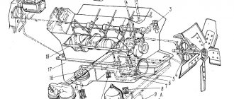
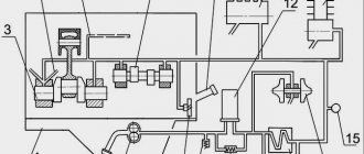
Lubrication diagram on a cross section of an engine
Figure 7 - Cross section of the ZMZ 406 engine (lubrication diagram)
1 - oil pump; 2 - oil sump; 3 - oil pump bypass valve;
4 - thermal valve; 5 - central oil line; 6 — oil filter;
7, 8, 10, 11, 12, 14, 17, 18, 19 — oil supply channels; 9 — fitting of the thermal valve for draining oil into the radiator; 13 — oil filler pipe cover; 15 — oil level indicator handle;
16 — emergency oil pressure indicator sensor; 20 - crankshaft;
21 — rod oil level indicator; 22 — connection hole for the oil supply hose from the radiator; 23 - oil drain plug
The lubrication system includes: oil sump, oil pump with inlet pipe and pressure reducing valve, oil pump drive, oil passages in the cylinder block, cylinder head and crankshaft, full-flow oil filter, oil level indicator rod, thermal valve, oil filler cap, oil drain plug , emergency oil pressure sensor and oil cooler.
Oil circulation occurs as follows. Pump 1 sucks oil from crankcase 2 and delivers it through the cylinder block channel to thermal valve 4.
At an oil pressure of 4.6 kgf/cm 2, the pressure reducing valve 3 of the oil pump opens and the oil is transferred back to the suction zone of the pump, thereby reducing the increase in pressure in the lubrication system.
The maximum oil pressure in the lubrication system is 6.0 kgf/cm2.
When the oil pressure is above 0.7-0.9 kgf/cm 2 and the temperature is above 79-83 ° C, the thermal valve begins to open a passage for the oil flow into the radiator, diverted
through fitting 9. The temperature of full opening of the thermal valve channel is 104-114 °C. The cooled oil from the radiator returns to the oil sump through hole 22. After the thermal valve, the oil flows to the full-flow oil filter 6.
The purified oil from the filter enters the central oil line 5 of the cylinder block, from where through channels 18 it is supplied to the main bearings of the crankshaft, through channels 8 - to the intermediate shaft bearings, through channel 7 - to the upper bearing of the oil pump drive shaft and is also supplied to the lower hydraulic tensioner camshaft drive chains.
From the main bearings, oil is supplied through the internal channels 19 of the crankshaft 20 to the connecting rod bearings, and from them through the channels 17 in the connecting rods it is supplied to lubricate the piston pins. To cool the piston, oil is sprayed onto the piston crown through a hole in the upper end of the connecting rod.
From the upper bearing of the oil pump drive shaft, oil is supplied through transverse drillings and the internal cavity of the shaft to lubricate the lower bearing of the shaft and the supporting surface of the driven gear of the drive (see Fig. 1.21). The oil pump drive gears are lubricated by a stream of oil sprayed through a hole in the central oil line.
Rice. 1.18. Lubrication system diagram: 1 - oil pump; 2 - oil sump;
3 — oil pump pressure reducing valve; 4 - thermal valve; 5 - central oil line; 6 — oil filter; 7, 8, 10, 11, 12, 14, 17, 18, 19 — oil supply channels; 9 — fitting of the thermal valve for draining oil into the radiator; 13 — oil filler pipe cover; 15 — oil level indicator handle; 16 — emergency oil pressure indicator sensor; 20 - crankshaft; 21 — rod oil level indicator; 22 — connection hole for the oil supply hose from the radiator; 23 - oil drain plug
From the central oil line, oil flows through channel 10 of the cylinder block into the cylinder head, where through channels 12 it is supplied to the camshaft supports, through channels 14 to the hydraulic pushers, and through channel 11 to the hydraulic tensioner of the upper camshaft drive chain.
Flowing out of the gaps and flowing into the oil sump at the front of the cylinder head, the oil ends up on the chains, tensioner arms and camshaft drive sprockets.
At the rear of the cylinder head, oil flows into the oil sump through the head hole through a hole in the boss of the cylinder block.
Oil is poured into the engine through the oil filler pipe of the valve cover, closed by a cover 13 with a rubber seal. The oil level is controlled by the marks on the 21 oil level indicator: the upper level is “MAX” and the lower level is “MIN”. The oil is drained through a hole in the oil sump, closed by drain plug 23 with a sealing gasket.
Oil purification is carried out by a mesh installed on the inlet pipe of the oil pump, filter elements of a full-flow oil filter, and also by centrifugation in the crankshaft channels.
Oil pressure is monitored by the emergency oil pressure indicator (warning lamp on the instrument panel), sensor 16 of which is installed in the cylinder head. The emergency oil pressure indicator lights up when the oil pressure drops below 40-80 kPa (0.4-0.8 kgf/cm2).
The drive gear 1 is fixedly fixed on the shaft 3 using a pin, and the driven gear 5 rotates freely on an axis 4, pressed into the pump housing 2. At the upper end of the roller 3 there is a hexagonal hole into which the hexagonal shaft of the oil pump drive fits.
Centering of the pump drive shaft is achieved by fitting the cylindrical protrusion of the pump housing into the bore of the cylinder block.
The pump body is cast from aluminum alloy, the partition 6 and gears are made of cermet. A cast aluminum alloy inlet pipe 7 with a mesh, in which a pressure reducing valve is installed, is attached to the body with three screws.
Oil path from pump to timing valve assembly
The gear-type oil pump is installed inside the oil sump and is attached to the cylinder block with two studs. The pump body is made of aluminum alloy, the pump cover is made of cast iron, and the pump gears are made of sintered metal. The drive gear is secured to the shaft with a pin, the driven gear rotates freely on an axis pressed into the pump housing.
A 0.3 mm thick cardboard gasket provides the necessary clearance between the ends of the gears and the cover. A cast aluminum alloy oil receiver with a mesh is attached to the cover. A pressure reducing valve is placed in the pump housing. Oil from the pump is supplied to the oil filter through channels in the cylinder block and an outer tube on the left side of the block.
From the oil filter, oil is supplied through channels in the block to the crankshaft main bearings and camshaft bearings, from the crankshaft main bearings through channels in the crankshaft, oil is supplied to the connecting rod bearings, and from the camshaft bearings through channels to the cylinder head to lubricate the valve rocker arms and top rod tips.
The plunger-type pressure reducing valve is located in the oil pump housing and is adjusted at the factory by installing a calibration spring. The adjustment should not be changed during operation. Oil pressure is determined by a gauge whose sensor is screwed into the oil line of the cylinder block.
In addition, the system is equipped with an emergency oil pressure indicator, the sensor of which is screwed into the lower part of the oil filter housing. The emergency oil pressure indicator lights up at a pressure of 0.4…0.8 kgf/cm 2 .
The oil pump is driven from the camshaft by a pair of helical gears. The drive gear is steel, cast into the body of the camshaft, the driven gear is steel, nitro-carburized, secured with a pin on a shaft rotating in a cast-iron housing. A sleeve is placed on the upper end of the shaft and secured with a pin, which has a slot shifted 1.5 mm to the side to drive the ignition distributor sensor. An intermediate hexagonal shaft is pivotally connected to the lower end of the shaft, the lower end of which fits into the hexagonal hole of the oil pump shaft.
The shaft in the drive housing is lubricated with oil, which is sprayed by the moving parts of the engine. The sprayed oil, flowing down the walls of the block, enters a slot - a trap at the lower end of the housing shank and through the hole enters the shaft surface.
The hole for the shaft in the housing has a helical groove, thanks to which the oil is evenly distributed along its entire length when the shaft rotates. Excess oil from the upper cavity of the drive housing flows back into the crankcase through a channel in the housing. The drive gears are lubricated by a stream of oil flowing from a 2 mm diameter hole in the cylinder block and connected to the fourth camshaft support, which has an annular groove.
The oil filter is full-flow, with a cardboard replaceable element, located on the left side of the engine. All the oil pumped into the system passes through the filter. The filter consists of a housing, a cover, a central rod and a filter element.
At the top of the central rod there is a bypass valve, which, when the filter element is clogged, allows oil to pass through it into the oil line. The resistance of a clean filter element is 0.1…0.2 kgf/cm2, the bypass valve begins to bypass oil when the resistance increases as a result of filter clogging to 0.6…0.7 kgf/cm2.
The oil cooler serves for additional cooling of the oil when operating the car in the summer, as well as during long-term driving at speeds above 100-110 km/h. The oil cooler is connected to the engine oil line using a rubber hose through a shut-off valve and a safety valve, which are installed on the left side of the engine.
Read more: How to paint a light bulb blue
The position of the faucet handle along the hose corresponds to the open position of the faucet, and across it corresponds to the closed position.
The safety valve opens the passage of oil into the radiator at a pressure above 0.7…0.9 kgf/cm 2 . The oil from the radiator is drained through a hose through the timing gear cover (on the right side of the engine) into the crankcase.
The engine crankcase ventilation is closed, forced, operating as a result of vacuum in the intake manifold and in the air filter. When the engine is running at idle and at partial loads, gases from the crankcase are sucked into the intake pipe, and at full load - into the air filter and intake pipe.
Rice. 1.20. Reducing valve: 1 - plunger; 2 - spring; 3 — washer; 4 - cotter pin
On the intermediate shaft, using a segment key 3, drive gear 2 is installed and secured with a flange nut. Driven gear 7 is pressed onto shaft 8, which rotates in the bores of the cylinder block. A steel sleeve 6 is pressed into the upper part of the driven gear, having
internal hex hole. A hexagonal roller 9 is inserted into the hole in the bushing, the lower end of which fits into the hexagonal hole of the oil pump roller.
From above, the oil pump drive is closed with a cover 4, secured through a gasket 5 with four bolts. When rotating, the driven gear is pressed against the drive cover by its upper end surface.
Rice. 1.21. Oil pump drive: 1 - intermediate shaft; 2 - drive gear;
3 - key; 4 - cover; 5 - gasket; 6 — bushing; 7 — driven gear; 8 - roller: 9 - hexagonal roller of the oil pump drive
The drive and driven helical gears are made of high-strength cast iron and nitrided to improve their wear resistance. The hexagonal roller is made of alloy steel and carbon nitrided. Drive roller
8 steel, with local hardening of the supporting surfaces with high frequency currents.
f. "Avtoagregat", Livny or 406.1012005-02 f. "BIG-filter", St. Petersburg.
For installation on the engine, use only the specified oil filters, which ensure high quality oil filtration.
Filters 2101C-1012005-NK-2 and 406.1012005-02 are equipped with a bypass valve filter element, which reduces the likelihood of unclean oil entering the lubrication system when starting a cold engine and extreme contamination of the main filter element.
About ZMZ engines
Before talking about oil pressure, it is worth introducing the reader to the engine itself. ZMZ engines are produced by the Zavolzhsky Motor Plant. They have 4 cylinders and 16 valves.
ZMZ engines are produced by the Zavolzhsky Motor Plant
These engines are installed on Volga, UAZ, GAZelle, and Sobol cars. The family includes motors ZMZ-402, 405, 406, 409, 515 and a number of their special modifications. ZMZ engines have their advantages:
- good maintainability;
- simplicity of the device;
- low demands on fuel quality.
But there are also disadvantages:
- the timing drive is very bulky;
- the reliability of the chain tensioner in the timing drive leaves much to be desired;
- The piston rings are of an archaic design. As a result, large losses of lubrication and power failures are observed;
- The overall quality of casting and heat treatment of individual engine parts is getting worse every year.
Standard oil pressure in ZMZ engines
The pressure in the lubrication system is measured only with a well-warmed engine idling. The crankshaft rotation speed at the time of measurement should not exceed 900 rpm. Here are the ideal oil pressure standards:
- for motors ZMZ 406 and 409, a pressure of 1 kgf/cm² is considered ideal;
- for motors ZMZ 402, 405 and 515, the ideal pressure is 0.8 kgf/cm².
It should be noted here that the highest pressure in the lubrication system of a ZMZ engine can theoretically reach 6.2 kgf/cm², but in practice this almost never happens. As soon as the oil pressure reaches 5 kgf/cm², the pressure reducing valve in the engine opens and excess oil flows back to the oil pump. So the oil can reach a critical point only in one case: if the pressure relief valve is stuck in the closed position, and this happens extremely rarely.
Pressure and emergency oil pressure sensors for ZMZ 405, 406, 409 engines
In order to monitor the pressure in the lubrication system of the ZMZ 405, 406 and 409 engines, two separate sensors are provided. One of them records the pressure value, and the second reacts to its critical drop.
Characteristics, design and principle of operation of the oil pressure sensor
The oil pressure sensor (OPS) is used to measure the lubricant pressure in the system. ZMZ power plants use MM358 type sensors with the following characteristics:
- working element - rheostat;
- rated current, A - 0.15;
- operating range, kgf/cm 2 – 0–6;
- resistance in the absence of pressure, Ohm - 159–173;
The design of the MM358 pressure sensor consists of:
- housings with fittings;
- membranes;
- pusher
- rheostat;
- rheostat drive elements.
The MM358 sensor works together with the pressure indicator located on the vehicle’s instrument panel. It has an electromechanical design that responds to changes in sensor resistance.
The operating principle of the MM358 sensor is as follows: when the engine is not running, there is no pressure in the lubrication system. The resistance of the sensor, in accordance with its characteristics, is 159–173 Ohms. When the power unit starts, the pressure increases, and the oil begins to act on the membrane, bending it inside the housing. By bending, it moves the transmission lever through the pusher, which, in turn, moves the rheostat sliders to the right, reducing the resistance of the sensor. The pointer reacts to this decrease by moving the arrow to the right.
Characteristics, design and principle of operation of the emergency oil pressure sensor
The emergency sensor is designed to inform the driver about a drop in oil pressure in the system to critical levels. In power units ZMZ 405, 406 and 409, emergency oil pressure sensors of type MM111D or similar are installed, manufactured under catalog numbers 2602.3829, 4021.3829, 6012.3829. These are contact-type devices, the operating principle of which is based on the closing and opening of contacts.
Characteristics of the MM111D sensor:
- working element - diaphragm;
- rated voltage, V - 12;
- response at pressure, kgf/cm 2 – 0.4–0.8;
- seat thread size, in inches – ¼.
A spring-loaded diaphragm is located inside the device body. A contact plate is attached to it, which in the non-operating state is closed with the body (ground) of the sensor. While the engine is running, lubricant under pressure enters the housing through a special hole and pushes back the diaphragm. The contacts are then opened.
The emergency pressure sensor works in tandem with a signaling device, which is located on the instrument panel. It is made in the form of a red butter dish. When we turn on the ignition without starting the engine, the oil can should burn. This indicates that voltage is applied to the sensor, but there is no pressure in the system. 3–5 seconds after starting the engine, the pressure in the system increases and reaches operating values. The oil acts on the diaphragm, the contacts open and the alarm goes off.
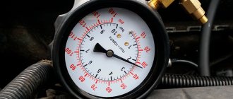
Checking the oil pressure
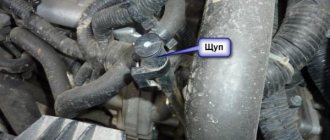
The oil pressure is displayed on the car's dashboard. The problem is that you can’t always trust these numbers, since devices can also break down and start giving incorrect readings. It often happens that the oil pressure is normal, but the instruments show that there is no pressure at all. For this reason, it is advisable to simply inspect the vehicle. Here's how it's done:
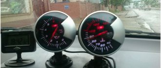
If all of the above measures do not produce results, and the cause of the low pressure has not been identified, the last option remains: use an additional pressure gauge.
Signs of low oil pressure
If the oil pressure in the engine has dropped sharply, it is impossible not to notice it. Here are the main signs that something is wrong with the engine lubrication system:
- the engine began to overheat quickly. At the same time, there is more exhaust gas, and the exhaust has a black color, which is especially noticeable when the car picks up speed;
- bearings and other parts subject to intense friction began to wear out very quickly;
- The engine began to knock and vibrate. The explanation is simple: there is little lubrication in the engine, the rubbing parts gradually wear out and the gaps between them increase. Eventually the parts become loose and begin to knock and vibrate;
- burning smell in the cabin. If the oil pressure is reduced, it begins to oxidize rapidly and burns out. And the driver smells combustion products.
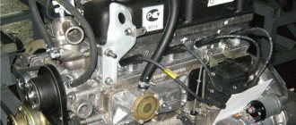
How to independently replace ZMZ 405, 406, 409 engines
Tools:
- slotted screwdriver;
- keys for 17 and 22;
- automotive sealant;
- dry rag;
- marker.
Replacement procedure:
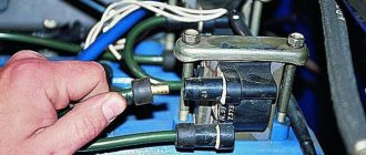
- Disconnect the ground wire from the battery.
- Using a slotted screwdriver, unscrew the screw that presses the tip of the pressure sensor power wire. Disconnect the wire.
- If you decide to replace both sensors, use the same tool to unscrew the fastening of the emergency sensor power wire.
- To avoid mixing up the wires, mark them with a marker.
- Using a 17mm wrench, unscrew the oil pressure sensor. Let's put it aside.
- Using a 22 wrench, unscrew the emergency oil pressure sensor.
- Carefully wipe the sensor seats and remove any remaining old sealant.
- Lubricate the sensor fittings with a thin layer of automotive sealant. Let it dry a little (30 s).
- We screw in the new sensors using keys 17 and 22.
- Connect the power wires.
- We connect the ground to the battery.
- We check the operation of the sensors.
Causes of low oil pressure and their elimination
First of all, it should be noted that a drop in oil pressure is a malfunction that is a common “disease” of all engines of the ZMZ family, regardless of their model. There are no special nuances associated with this malfunction and characteristic of any individual engine from the ZMZ family. For this reason, the reasons for the drop in oil pressure in the ZMZ-409 engine, which is by far the most popular in our country, will be discussed below. It should also be said here that the most common cause of a drop in oil pressure is an incorrect viscosity index, also known as SAE. This driver error can cause engine oil to become too thin in hot weather. Or vice versa, in severe frost it can quickly thicken. Therefore, before looking for a problem in the engine, the car owner should ask himself a simple question: did I fill in the oil?
Sudden drop in engine oil
If the oil pressure in a ZMZ engine suddenly drops, this can happen for two reasons:
It should be noted here that the above breakdowns occur quite rarely. In order for this to happen, the driver must absolutely “start” the engine and not change the oil in it for years, or for a long time use a lubricant that is not suitable in viscosity.
Gradual drop in oil pressure
This problem is very common in all engines of the ZMZ family, without exception. It can arise due to many factors: these are the design errors mentioned above, improper maintenance, natural wear and tear of parts, and much more. We list the most common reasons for a gradual drop in oil pressure:
- oil filter wear.
Gazelle drivers strongly recommend changing these filters every 5 - 6 thousand km, and changing the oil every 10 thousand km. If this is not done, a dirty sediment appears in the oil, no matter how good it is, which gradually clogs the oil filter. And at this moment the driver observes the above signs of a drop in oil pressure; Oil filters on ZMZ engines must be changed as often as possible - general engine wear. First of all, this applies to the intermediate shaft, where the main pressure losses occur. This happens due to wear of the shaft support bushings. The hydraulic chain tensioner, which is also not durable, can also wear out. In addition, the cylinder head itself and the camshafts often wear out. With the slightest wear in this system, the pressure begins to drop, and oil consumption gradually increases. A worn out oil pump, which is simply unable to supply enough lubricant to the engine, can also cause a drop in pressure. And finally, hydraulic compensators on the valves can fail, which also reduces the lubricant pressure. There is only one solution to all of the above problems: engine overhaul;
- Reducing valve wear.
The pressure relief valve has a spring that can weaken over time. As a result, some of the oil goes back to the oil pump, which leads to a decrease in oil pressure. Some car enthusiasts solve the problem simply: they place a couple of small washers under the spring in the valve. But this, as you might guess, is only a temporary measure. And the only correct solution is to replace the pressure reducing valve with a new one (you won’t be able to purchase a new spring for the valve - they are not sold separately); The spring is the main component of the pressure reducing valve in the ZMZ engine - oil cooler leak. Radiators in which the oil is cooled are found on many cars with ZMZ engines. However, these radiators are used extremely rarely, since their quality leaves much to be desired. Of particular note is the oil cooler valve. This faucet is constantly leaking. Solution: stop using an oil cooler, since with the correct selection of oil, the need for this device simply disappears. Or the second option: install a high-quality valve on the radiator (preferably a ball valve, made in Germany, but in no case Chinese).
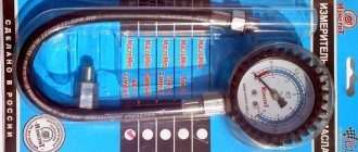
How to check the oil pressure sensor
If you have any suspicions about the performance of the pressure sensor, do not be lazy to check it. This can be done both at a service station and at home. But in the latter case, you will need to purchase a special pressure gauge. It costs about 300 rubles, but such a thing will be useful in the future. In addition to this, you will also need a slotted screwdriver, a 22 mm wrench and electrical tape.
Check procedure:
Video: checking the oil pressure in the system
Other faults
However, a deviation in the pressure value can be associated with both wiring faults and problems with the indicator itself. Don’t be lazy to carry out additional diagnostics. Her order is as follows.
Turn on the ignition. The pointer arrow should deviate to the right and then return to its original position. If the arrow does not deviate, use a slotted screwdriver to unscrew the screw securing the sensor power wire, disconnect it and touch ground. The arrow has deviated - there is a short circuit in the sensor's power supply wiring. If not, the problem should be looked for in the pressure indicator.