Device, spare parts and components.
SPARE PARTS FOR TRACTORS
ADJUSTING MTZ TRACTORS ___________________
DIESEL ENGINE PARTS ___________________
MTZ SPARE PARTS CATALOG ___________________
TECHNICAL CHARACTERISTICS OF TRACTORS ___________________
SPECIAL EQUIPMENT BASED ON MTZ AND ATTACHMENTS ___________________
AGRICULTURAL MACHINERY AND EQUIPMENT ___________________
Engine lubrication system D-245
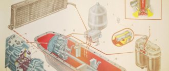
The D-245 engine lubrication system is combined (Fig. 1): some parts are lubricated under pressure, others by splashing. The crankshaft and camshaft bearings, the idler gear bushing, the connecting rod bearing of the compressor crankshaft, the valve drive mechanism (rocker arms) and the engine turbocharger shaft bearing are lubricated under pressure from the oil pump.
Sleeves, pistons, piston pins, rods, pushers, camshaft cams and fuel pump drive MTZ-892, MTZ-92P are lubricated by splashing. On diesel engines with a full-flow centrifugal oil filter installed, a diagram of the lubrication system in accordance with Figure 1a.
Fig. 1a - Lubrication system D-245
1 — oil sump; 2 – piston cooling nozzles; 3 - crankshaft; 4 - camshaft; 5 — intermediate gear; 6 — oil filler neck; 7 — oil sump plug; 8 — oil receiver; 9 — oil pump; 10 – oil radiator; 11 – pressure reducing valve; 12 – oil filter; 13 – bypass valve; 14 – safety valve; 15 – pressure sensor; 16 – turbocharger; 17 – compressor; 18 – high pressure fuel pump; 19 – oil channel of the rocker arm axis,
Oil pump D-245 MTZ-892, MTZ-92P - gear type, single-section, bolted to the cover of the first main bearing. The oil pump supplies oil through the pipe and channels of the cylinder block to the centrifugal filter 12, in which it is cleaned of foreign impurities, wear products and oil decomposition products due to heating and oxidation.
From the centrifugal filter, the purified oil enters the radiator for cooling and through the oil supply tube to the turbocharger shaft bearing 16. From the oil cooler, the oil enters the diesel line.
In the housing of the centrifugal oil filter D-245 there are pressure-reducing valves 11, drain valves 13, and safety valves 14. When starting the engine, unheated oil, due to the high resistance of the radiator, flows directly into the engine line through the pressure reducing (radiator) valve, bypassing the radiator.
The safety valve (centrifugal filter valve D-245) is used to maintain oil pressure in front of the filter rotor at 0.8 MPa. When the pressure rises above the specified value, part of the crude oil is drained through the valve into the diesel crankcase. The pressure reducing and safety valves are not adjustable.
With the MTZ-892, MTZ-92P engine running, it is strictly forbidden to unscrew the pressure reducing and safety valve plugs. The drain valve is adjusted to a pressure of 0.25. 0.35 MPa and serves to maintain the required oil pressure in the main diesel line. Excess oil is drained through the valve into the crankcase.
From the main line of the engine, oil flows through channels in the cylinder block to all crankshaft main bearings and camshaft journals. From the main bearings, oil flows through channels in the crankshaft D-245 to all connecting rod bearings. From the first main bearing, oil flows through special channels to the bushings of the intermediate gear and the fuel pump drive gear, as well as to the fuel pump.
The parts of the valve mechanism D-245 MTZ-892, MTZ-92P are lubricated with oil supplied from the rear camshaft bearing through the channels in the block, the cylinder head, drilling in the IV rocker post into the internal cavity of the rocker axis and through the hole to the rocker bushing, from which the channel goes to the adjusting screw and rod. The pneumatic compressor receives oil from the main line through drillings in the cylinder block and a special oil pipeline. The oil is drained from the compressor into the diesel crankcase.
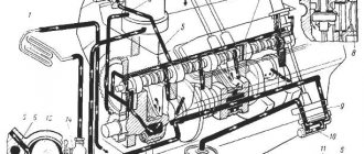
On diesel engines with an installed full-flow oil filter with a non-separable filter element and an oil cooler as part of the vehicle, the lubrication system diagram is in accordance with Figure 1b.
Fig. 1b - Lubrication system D-245 with a non-separable filter element and a liquid-oil heat exchanger
1 – oil sump; 2 – piston cooling nozzles; 3 – crankshaft, 4 – camshaft; 5 – intermediate gear; 6 – oil filler neck; 7 – oil sump plug; 8 – oil receiver; 9 – oil pump; 10 – liquid-oil heat exchanger (LHE); 11 – bypass valve; 12 – oil filter; 13 – bypass valve; 14 – safety valve; 15 – pressure sensor; 16 – turbocharger; 17 – compressor; 18 — high pressure fuel pump; 19 – oil channel of the rocker arm axis.
The D-245 oil pump, through the oil receiver 8, takes oil from the oil sump 1 and delivers it through the channels in the cylinder block and the channels of the oil filter housing to a full-flow oil filter, in which it is cleaned of foreign impurities, wear products and oil decomposition products due to heating and oxidation . From the oil filter D-245, the purified oil enters the radiator for cooling. From the oil cooler, oil flows into the oil line.
When starting the engine on cold oil, when the resistance to the passage of oil through the oil filter exceeds 0.13...0.17 MPa, the bypass valve 13 of the oil filter opens, the bypass (radiator) valve 11 of the oil cooler also opens, and the oil, bypassing the oil filter and oil radiator enters the oil line.
An adjustable safety valve 14 is built into the D-245 filter housing. It is designed to maintain oil pressure in the main oil line at 0.25. 0.35 MPa. Excess oil is drained through the valve into the diesel crankcase.
On diesel engines with an installed full-flow oil filter with a non-separable filter element and a liquid-oil heat exchanger - The D-245 oil pump, through the oil receiver 8, takes oil from the oil sump 1 and supplies it through the channels in the cylinder block and the channels of the oil filter housing to the liquid-oil heat exchanger, and then into a full-flow oil filter, in which it is cleaned of foreign impurities, wear products and oil decomposition products due to heating and oxidation. From the oil filter D-245, the purified oil enters the diesel oil line.
Diesel lubrication system D-245e3
The diesel lubrication system, in accordance with Figures 1 and 2, is combined: some parts are lubricated under pressure, others - by splashing
The crankshaft and camshaft bearings, the idler gear bushing, the connecting rod bearing of the compressor crankshaft, the valve drive mechanism (rocker arms) and the turbocharger shaft bearing are lubricated under pressure from the oil pump.
The liners, pistons, piston pins, rods, lifters, camshaft lobes and fuel pump drive are splash lubricated.
The oil pump of the lubrication system is gear type, single-section, bolted to the cover of the first main bearing.
The oil pump is driven by a gear mounted on the crankshaft.
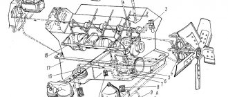
Figure 1 – Diagram of a diesel lubrication system with an oil cooler and a non-separable oil filter with a paper filter element
On diesel engines with an installed non-separable oil filter with a paper filter element and an oil cooler as part of the vehicle, a diagram of the lubrication system in accordance with Figure 1.
The oil pump 9, through the oil receiver 8, takes oil from the oil sump 1 and delivers it through the channels in the cylinder block and the channels of the oil filter housing to the full-flow oil filter 12, in which it is cleaned of foreign impurities, wear products and oil decomposition products due to heating and oxidation. From the oil filter, the purified oil enters the radiator 10 for cooling. From the oil cooler, oil flows into the diesel oil line.
When starting a diesel engine on cold oil, when the resistance to the passage of oil through the oil filter exceeds 0.13...0.17 MPa, the bypass valve 13 of the oil filter opens, the bypass (radiator) valve 11 of the oil cooler also opens, and the oil, bypassing the oil filter and oil radiator enters the oil line.
An adjustable safety valve 14 is built into the filter housing. It is designed to maintain oil pressure in the main oil line at 0.25...0.35 MPa. Excess oil is drained through the valve into the diesel crankcase.
In case of excessive clogging of the filter paper, when the resistance of the oil filter becomes higher than 0.13...0.17 MPa, the oil filter bypass valve also opens, and the oil, bypassing the oil filter, enters the oil line.
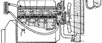
On diesel engines with a liquid-oil heat exchanger and a non-separable oil filter with a paper filter element - a diagram of the lubrication system in accordance with Figure 2.
The oil pump 9, through the oil receiver 8, takes oil from the oil sump 1 and delivers it through the channels in the cylinder block and the channels of the oil filter housing to the liquid-oil heat exchanger 10, and then to the full-flow oil filter 12, in which it is cleaned of foreign impurities, wear products and from oil decomposition products due to heating and oxidation.
From the oil filter, the purified oil enters the diesel oil line.
Bypass (reducing) valves are installed:
— in the body of the liquid-oil heat exchanger — 11 (response pressure value — 0.15 MPa);
- in the oil filter - 13 (response pressure value - 0.15 MPa).
When starting a diesel engine on cold oil, when the resistance to the passage of oil in the liquid-oil heat exchanger exceeds 0.15...0.2 MPa, the bypass valve opens and the oil, bypassing the liquid-oil heat exchanger, enters the oil filter, and when there is resistance in the oil filter 0.13...0.17 MPa, the oil filter bypass valve opens and the oil, bypassing the oil filter, enters the oil line. The bypass valves are unregulated.
An adjustable safety valve 14 is built into the filter housing, designed to maintain oil pressure in the main oil line at 0.25...0.35 MPa. Excess oil is drained through the valve into the diesel crankcase.
Figure 2 – diagram of a diesel lubrication system with a liquid-oil heat exchanger and a non-separable oil filter with a paper filter element
In case of excessive clogging of the filter paper, when the resistance of the oil filter becomes higher than 0.13...0.17 MPa, the oil filter bypass valve also opens, and the oil, bypassing the oil filter, enters the oil line.
When the diesel engine is running, it is strictly forbidden to unscrew the pressure reducing valve plug.
From the main diesel line, oil flows through channels in the cylinder block to all crankshaft main bearings and camshaft journals.
From the main bearings, oil flows through channels in the crankshaft to all connecting rod bearings. From the first main bearing, oil flows through special channels to the bushings of the intermediate gear and the fuel pump drive gear, as well as to the fuel pump.
The valve mechanism parts are lubricated with oil coming from the rear camshaft bearing through channels in the block, cylinder head, drilling in the IV rocker arm post into the internal cavity of the rocker arm axis and through the hole to the rocker arm bushing, from which it goes through the channel to the adjusting screw and rod.
Oil is supplied to the compressor from the main line through drillings in the cylinder block and a special oil pipeline. The oil is drained from the compressor into the diesel crankcase.
Oil is supplied to the bearing assembly of the turbocharger through a tube connected at the outlet of the oil filter housing. From the bearing assembly of the turbocharger, oil is discharged through a tube into the oil sump.
Maintenance of the D-245E3 lubrication system
To ensure normal operation of the diesel engine, observe the following requirements for servicing the lubrication system:
— fill the oil sump only with oil recommended by the manufacturer.
— change the oil and oil filter in a timely manner, guided by the deadlines or according to the information from the electronic diesel control system with the corresponding blink code;
- constantly monitor the oil pressure value using the pressure indicator located on the instrument panel (when the diesel engine is operating at a rated speed and coolant temperature of 85. 95 ° C, the oil pressure should be at the level of 0.25. 0.35 MPa, the value is allowed pressure on a cold engine up to 0.8 MPa);
Figure 1 – Adjusting oil pressure.
— adjust the pressure value in accordance with Figure 1 as follows:
— unscrew plug 4, remove gasket 5;
— in the channel of the oil filter housing 3, use a screwdriver 7 to turn the adjusting rod 6 one turn in the direction of increasing or decreasing the pressure value (depending on the actual pressure);
— install gasket 5 and tighten plug 4;
— if necessary, repeat these adjustment steps.
It is PROHIBITED to make adjustments while the diesel engine is running.
Checking the oil level in the diesel crankcase
Carry out the check before starting the diesel engine using an oil gauge located on the diesel cylinder block.
The oil level should be between the lower and upper marks of the oil gauge in accordance with Figure 2.
The check must be done no earlier than 3-5 minutes after stopping the diesel engine, when the oil has completely drained into the crankcase.
It is prohibited to operate a diesel engine with the oil level in the crankcase below the lower and above the upper marks on the dipstick.
Figure 2 - Checking the oil level in the diesel crankcase.
Changing the oil in the diesel crankcase
Change the oil in the crankcase of diesel engines every 10 thousand kilometers, and in cases of using backup oils or fuel with a high sulfur content - every 5 thousand kilometers.
Drain used oil only from a warm diesel engine.
To drain the oil, unscrew the oil sump plug. After all the oil has flowed out of the crankcase, screw the plug back into place.
Fill diesel oil through the oil filler pipe to the level of the top mark on the dipstick.
Fill the oil sump only with oil recommended in this manual and appropriate for the period of operation.
Replacing the oil filter
Figure 3 – Options for installing an oil filter without LMC and with LMC on D-245E3 diesel engines
Replace the oil filter every 10 thousand km or according to the results of diagnostics of the “COMMON RAIL” system in accordance with Figure 3 simultaneously with changing the oil in the diesel crankcase in the following sequence:
— unscrew the FM 009-1012005 or M5101 filter from fitting 3, using a special key or other available means;
— screw a new filter FM 009-1012005 or M5101 onto the fitting.
When installing the filter on the fitting, lubricate gasket 4 with engine oil.
After the gasket touches the supporting surface of filter housing 1, tighten the filter another 1.1.5 turns.
Install the filter on the housing only by hand.
D 245 how to increase oil pressure
Diesel lubrication system D-245.7, D-245.9, D-245.12S
1.2.2.7.1 Combined diesel lubrication system. The crankshaft and camshaft bearings, the intermediate gear bushings, the connecting rod bearing of the pneumatic compressor crankshaft, the turbocharger shaft bearing, as well as the valve drive mechanism are lubricated under pressure. Liners, pistons, piston pins, rods, lifters, camshaft lobes and fuel pump parts are splash lubricated.
1.2.2.7.2 Oil pump - gear type, single-section, bolted to the first main bearing cover. The pump supplies oil through the pipe and channels of the cylinder block to the oil filter, in which it is cleaned of foreign impurities, combustion products and wear. From the oil filter, the purified oil enters the radiator for cooling, as well as through the oil supply tube to the turbocharger shaft bearing. From the oil cooler, oil flows into the diesel line.
1.2.2.7.3 In the oil filter housing, in accordance with Figure 3, there are reduction valves 14 and safety valves 13.
1 – nut; 2 – bottom; 3, 9 – gasket; 4 – clamp; 5 – cap; 6 – filter element; 7 – bypass valve; 8 – spring; 10 – anti-drainage valve; 11 – washer; 12 – spring; 13 – safety valve; 14 – pressure reducing valve.
Figure 3 – Oil filter
When starting a diesel engine, unheated oil, due to the high resistance of the radiator, flows directly into the diesel line through the pressure reducing (radiator) valve, bypassing the radiator. The pressure reducing valve is unregulated.
The safety valve is adjusted to a pressure of 0.25 to 0.35 MPa and serves to maintain the required oil pressure in the main diesel line. Excess oil is drained through the valve into the diesel crankcase.
1.2.2.7.4 When the diesel engine is running, it is strictly forbidden to unscrew the plugs of the pressure reducing and safety valves of diesel engines D-245.7, D-245.9, D-245.12S
1.2.2.7.5 From the main diesel line, oil flows through the channels in the cylinder block to all crankshaft main bearings and camshaft journals. From the main bearings it goes through channels in the crankshaft to all connecting rod bearings. From the first main bearing, oil flows through special channels to the intermediate gear bushing and the fuel pump.
1.2.2.7.6 The valve mechanism parts are lubricated with oil coming from the rear camshaft bearing through channels in the block, cylinder head, drilling in the IV rocker arm post into the internal cavity of the rocker arm axis and through the hole to the rocker arm bushing, from which it goes through the channel to the adjusting screw and rod.
1.2.2.7.7 Oil is supplied to the pneumatic compressor from the main line through drilling holes in the cylinder block and a special oil pipeline. The oil is drained from the compressor into the diesel crankcase.
1.2.2.7.8 Instead of an oil filter with a replaceable filter element, upon customer request, it is possible to install a center bypass oil filter.
The centrifugal oil filter housing has pressure reducing, drain and safety valves.
When starting a diesel engine, unheated oil, due to the high resistance of the radiator, flows directly into the diesel line through the pressure reducing (radiator) valve, bypassing the radiator.
The safety valve (centrifugal filter valve) serves to maintain the oil pressure in front of the filter rotor at 0.7 MPa. When the pressure rises above the specified value, part of the unrefined oil is drained through the valve into the diesel crankcase.
The pressure reducing and safety valves are not adjustable.
The drain valve is adjusted to a pressure of 0.25 to 0.35 MPa and serves to maintain the required oil pressure in the main diesel line. Excess oil is drained through a valve into the diesel crankcase.
1.2.2.8 Electrical equipment and diesel starting system D-245.7, D-245.9, D-245.12S
1.2.2.8.1 Alternating current generators with a rated power of 1.2 kW and a rated voltage of 14 V or 28 V are installed by the consumer.
1.2.2.8.2 The generator is a non-contact electric machine with one-sided electromagnetic excitation and a built-in voltage regulator.
The generator operates in parallel with the battery and serves to recharge it, as well as to supply direct current to electricity consumers installed on a bus or car.
1.2.2.8.3 To start diesel engines, an electric starter with a rated voltage of 12 V or 24 V, as well as an electric torch heater and a flammable liquid are used.
1.2.2.8.4 The starter is a series-excited DC electric motor. The starter is turned on remotely, using an electromagnetic relay and a starter switch.
1.2.2.8.5 The electric torch heater is used to heat the air sucked into the cylinders in order to facilitate diesel starting.
1.2.2.8.6 To ensure starting at low ambient temperatures, all diesel engines have places for installing a pre-heater type PZhB-200 G.
Engine 245 oil sensor
Features and maintenance of the D-245.7E2 / D-245.9E2 engine lubrication system
Combined diesel lubrication system
The oil pump 9, through the oil receiver 8, takes oil from the oil sump 1 and supplies it through the channels in the cylinder block and the channels of the oil filter housing to the liquid-oil heat exchanger 10, and then to the full-flow oil filter 12 and to the diesel oil line.
From the main diesel line, oil flows through channels in the cylinder block to all crankshaft main bearings and camshaft journals.
From the main bearings, oil flows through channels in the crankshaft to all connecting rod bearings.
From the first main bearing
The oil flows through special channels to the bushings of the intermediate gear and the fuel pump drive gear, as well as to the fuel pump.
The valve mechanism parts are lubricated with oil coming from the rear camshaft bearing through channels in the block, cylinder head, drilling in the IV rocker arm post into the internal cavity of the rocker arm axis and through a hole in the rocker arm bushing, from which it goes through the channel to the adjusting screw and rod.
Oil is supplied to the compressor from the main line through drillings in the cylinder block and a special oil pipeline. The oil is drained from the compressor into the diesel crankcase.
Oil is supplied to the bearing assembly of the turbocharger through a tube connected at the outlet of the oil filter housing.
From the bearing assembly of the turbocharger, oil is discharged through a tube into the oil sump
When starting a diesel engine on cold oil, when the resistance to the passage of oil in the liquid-oil heat exchanger exceeds 0.15-0.2 mPa, the bypass valve opens and the oil, bypassing the liquid-oil heat exchanger, enters the oil filter, and with resistance in the oil filter filter 0.13. 0.17 mPa, the oil filter bypass valve opens and the oil, bypassing the oil filter, enters the oil line.
The bypass valves are unregulated.
An adjustable safety valve 14 is built into the filter housing, designed to maintain oil pressure in the main oil line at 0.25. 0.35 mPa. Excess oil is drained through the valve into the diesel crankcase.
In case of excessive clogging, when the oil filter resistance becomes higher than 0.13-0.17 mPa, the filter bypass valve also opens, and the oil, bypassing the oil filter, enters the oil line.
Attention! When the diesel engine is running, it is strictly forbidden to unscrew the pressure reducing valve plug!
The oil filter (Fig. 2) consists of a housing assembled with valves and a replaceable one-piece filter mod. FM 009-1012005.
The non-separable filter has anti-drainage and bypass valves.
In case of excessive filter clogging or when starting a diesel engine on cold oil, when the filter resistance becomes higher (0.13-0.17) MPa, the bypass valve opens and the oil, bypassing the filter paper, enters the oil line.