IR night vision devices. Night sights for small arms of the USSR
Night sight devicePurpose and design of the NSPU sight
72. The NSPU sight (universal night rifle sight) is installed on the AKMN (AKMSN), AK74N (AKS74N) assault rifles, RPKN (RPKSN), RPK74N (RPKS74N) machine guns, PKMN (PKMSN), SVDN sniper rifle, RPG-7N hand-held anti-tank grenade launcher ( RPG-7DN) (Fig. 52).
The NSPU sight is designed to detect targets and conduct aimed fire at them at direct shot ranges from all of the above weapons. With increased illumination (on a moonlit night, in the presence of external lights), the visibility range increases; in low light conditions (low clouds, reduced atmospheric transparency), the visibility range decreases.
The weight of the sight in the combat position is 2.2 kg, in the stowed position - 3.5 kg. The sight magnification is 3.5x. Field of view 5°40″ Resolution 1.8″. The operating time of the sight with one battery is about 6 hours. At low air temperatures, the operating time of the sight is reduced.
Rice. 52. NSPU sight on the weapon:
a - automatically; b - on a light machine gun; on a Kalashnikov machine gun: g - on a sniper rifle; c - on a hand-held anti-tank grenade launcher
73. The NSPU sight (Fig. 53) consists of a body, a lens, an aiming angle mechanism, a voltage converter, a high-voltage adjustment unit, an eyepiece, a battery, a diaphragm and a light filter.
74. The sight body is designed to accommodate and assemble all parts and mechanisms of the sight and attach it to the weapon. The lens is screwed into the front part of the sight body, and the eyepiece is screwed into the back. Inside the case there are: in the cylindrical part - an electron-optical converter in the base, which is pressed in with a lid; a shock-absorbing ring is installed between the lid and the image intensifier; in the thickened part and below in a box with a lid - a voltage converter, a high-voltage unit, a voltage divider and a compartment with a lid for the battery.
The electrical connection of the voltage converter with the high-voltage unit is carried out by an adapter. To measure the voltage of the high-voltage unit, there is a hole in the cover, closed with a plug with a rubber gasket and a washer.
The cover is attached to the body with screws. The eyepiece frame with lenses is screwed into the lid. An eyecup is placed on the protrusion of the lid, which is clamped with a spring ring.
The aiming angle mechanism is attached to the front of the case on the left with screws and fixed with pins. Voltage is supplied to the light bulb through a wire and contact
Rice.
53. NSPU sight; a - general view; b - section: 1 - diaphragm; 2 — guide (LEFT, STP, RIGHT); 3 - light bulb; 4 - wire; 5 — body; 6 — drying cartridge; 7 — eyecup; 8 - latch; 9 - cover; 10 — bracket; 11 — handle; 12 — stopper; 13 — clamping screw; 14 — reticle brightness handwheel OFF; 15 - cover; 16 — handwheel; 17 — scale; 15, 20, 29 and 33 - lenses; 19, 21, 23 and 28 - frames; 25 - converter; 26 - cover; 27 — shock absorber; 30 - plug; 31 high voltage units; 32 - aiming angle mechanism
The sight is mounted on a weapon using a clamping device, which consists of a bracket, a clamping screw, a latch, a stopper and a handle.
75. The lens is screwed into the front part of the sight frame. In frames 23 (Fig. 53) with aperture holes designed to reduce the influence of scattered light, which degrades the quality of the target image, there are lenses 22 and 24. Both frames are fixed in a common frame, which is screwed into the body and secured with screws. Lens 20 with a prism in the frame is secured in the body with screws, and lens 18 is secured with a ring.
76. The aiming angle mechanism (Fig. 54) is located in the housing. A lens in a frame is screwed into the body, and an AR-90° prism and a leash are attached to the guide. The spring presses the leash against the guide (LEFT, RIGHT, STP). One end of the spring is fixed in the guide, the other in the bushing. When the guide is rotated, the AP-90° prism rotates, as a result of which the reticle image in the field of view shifts to the left or right relative to the optical axis of the sight—the sight is aligned in direction.
Rice.
54. Mechanism of aiming angles 1 - Guide LEV, STP, RIGHT; 2 - nut; 3 and 11 — bushings; 4 — clamp; 5 - spring; 6 - guide; 7 — body; 8 - gasket; 9 — light bulb; 10 and 12 — contacts; 13 — bar; 14 — mesh in the frame; 15 — prism in a frame; 16 - spring; 17 — prism guide; 18 — pin; 19 - nut; 20 — alignment screw; 21 — scale; 22 - screw; 23 — handwheel UP, STP, DOWN; 24 - 24 and 25 - limit washers; 26 - key; 27 — leash; 28 — prism AR-90°; 29 — lenses in the frame; 30 - bushing;
31 - body When the handwheel is turned UP, STP, DOWN and the alignment screw, the prism guide moves along the key, and the prism in the frame and the reticle move with it, i.e. the image of the reticle in the field of view shifts up and down relative to the optical axis of the sight - The aiming angles are entered into the sight, and with the screws unscrewed 1-2 turns, the height of the aisle is adjusted.
The directional alignment scale printed on the nut has 30 divisions; the price of one division is 0-00.5. Each rotation of the guide by one division is recorded.
The aiming angle scale is calibrated in hundreds of meters. The sight kit includes a set of aiming angle scales: for AKMN (AKMSN) assault rifles, RPK74N (RPKS74N) machine guns, RPKN (RPKSN) - with graduations from 3 to 7; for AK74N (AKS74N) assault rifles, PKMN (PKMSN) machine guns, SVDN sniper rifle - with graduations from 4 to 10; for RPG-7N (RPG-7DN) grenade launchers - with “+” and “-” signs
The weapon sample is engraved directly on the scale. One of the scales is installed on the sight, the rest of the scales are stored in the storage box.
Each rotation of the handwheel by one division is recorded. On the handwheel there is a height adjustment scale with a division value of 0-00.5.
The direction of rotation of the handwheel and guide is indicated by arrows with inscriptions.
The sight reticle (Fig. 55) serves for aiming and can be used to determine the range to local objects and targets.
There are aiming marks on the reticle. The upper row of aiming marks is designed for aiming when firing from RPG-7N (RPG-7DN) grenade launchers up to 300 m and when firing from other types of weapons at all ranges according to the aiming angle scales. The strokes marked with the number 4 serve for aiming when firing from a grenade launcher at a distance of 400 m, and the bottom stroke - at 500 m.
Rice. 55. View of the field of view of the NSPU sight
The light bulb for illuminating the reticle is screwed into the body of the aiming angle mechanism
77. Electron-optical converter with voltage divider (Fig. 56) is placed in a casing, which, together with the protective
protective glass provides electrical insulation of the image intensifier from the metal parts of the sight. The casing is closed with a screen that protects the image intensifier from electromagnetic interference. The divider contacts are placed on the corresponding converter rods. A shock absorber is installed between the converter and the casing.
Rice. 56. Electron-optical converter:
1 — screen; 2 - casing; 3 — image intensifier; 4 - voltage divider; 5— shock absorber; 6 — protective glass; 7 - board with photoresistor
The voltage at the high-voltage inputs (bars) of the image intensifier tube from the photocathode to the screen of the third camera is distributed according to the 0-10-20-30 kV scheme
The divider distributes the voltage across the rings of the electron-optical converter and is made of nine resistors, three of which serve to protect the image intensifier from failure when illuminated by the flames of shots and shell explosions.
78. The voltage converter is designed to convert the DC voltage of 2.5 V of the battery into an AC voltage of 6 kV. The assembled converter (transformer, panel with transistors and resistors) is mounted in the lower compartment of the sight body.
79. The high-voltage unit is designed to rectify and multiply the 6 kV AC voltage converter into a 30 kV DC voltage. It consists of 14 selenium rectifiers connected in series, 3 or 2 in each arm, and 6 capacitors. All elements of the high-voltage block are filled with compound, forming a single block.
80. The adjustment unit (Fig. 57) is designed to turn the aisle on and off, set the required initial brightness of the reticle illumination light bulb, and to automatically adjust the brightness of the screen and reticle when natural night illumination changes.
There is a resistor on the board attached to the cover. The microswitch and pusher are attached to the stand, and the stand is attached to the cover. The second end of the pusher touches the lower end of the cap.
Handwheel BRIGHTNESS GRID, OFF connected to the cap. The movable part of the resistor is also connected to it through a bushing, ring and pin.
With the sight turned off, when setting the arrow on the handwheel against the inscription OFF. the end of the pusher is in the recess on the torus
this is the cap. When the handwheel is turned clockwise, the pusher comes out of the recess and presses the microswitch contact, thereby turning on the sight. By further turning the handwheel, the required initial brightness of the reticle illumination lamp is set.
Rice.
57. Adjustment block: 1 - cover; 2 — handwheel BRIGHTNESS GRID, OFF; 3 - bushing; 4 - ring; 5 - check; 6 - screw; 7 - cap;
8 — clamp; 9 - resistor; 10 - microswitch; 12 — pusher; 12 — board In extreme positions, the rotation of the handwheel is limited by a protrusion in the board. The position of the handwheel is fixed with a lock.
81. The eyepiece is screwed into the back of the aisle body. The purpose and design of the eyepiece are set out in Art. 14 of this Guide.
In the eyepiece part of the sight there is a drying screw, consisting of a nipple (plug), a cover and a rubber gasket. The drying screw is used to dry the inner strip of the sight with dry nitrogen or air. When blowing, nitrogen or air comes out through a hole, which is closed with a plug with a rubber gasket and a washer.
During operation, the air inside the sight is constantly dried by the silica gel of the drying cartridge. Silica gel saturated with moisture has a bluish color. As it becomes saturated with moisture, the color of the silica gel changes and, when completely saturated, has a pale pink or off-white color.
The condition of the silica gel can be viewed through the desiccant glass.
82. The 2NKBN-1.5 battery is the power source for the sight. Battery capacity is 1.5 Ah. The sight's power is turned on by a microswitch, which is mechanically connected to the resistor's handwheel. The design and operation of batteries are set out in Art. 8.
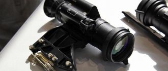
83. The diaphragm (Fig. 58) protects the sight from flare when aligning it during the day (at dusk), as well as when shooting during high night illumination. The amount of light entering the scope is limited and controlled by an iris diaphragm and two neutral density filters.
Rice. 58. Aperture:
1 — light filters; 2 - movable ring; 3 - spring; 4 — clamp; 5 — body; 6 — clamp; 7 — oil seal; 8 - petal
The iris diaphragm, consisting of petals, is located between the filters.
At the end of the body there are the inscriptions OTK., CLOSED. which correspond to a fully open or closed iris diaphragm.
When the movable ring rotates, the movement is transmitted to the blades, while the light opening increases or decreases (depending on the direction of rotation), thereby adjusting the light opening of the aperture.
To prevent spontaneous opening or closing of the diaphragm, a latch with a spring is installed in the movable ring. Fixation is carried out using teeth on the inner surface of the movable ring. The diaphragm is placed on the main body of the sight and secured with a pin that fits into the grooves of the diaphragm body.
| Rice. 59. Light filter in frame: 1 - spring; 2 - good; 3 - light filter |
84. A light filter in the frame (Fig. 59) serves to increase the contrast of the target image when it is observed against a green background in high light conditions. The light filter is attached to the protrusions of the aisle body in the same way as the diaphragm is attached.
Rice.
60. Sight accessories: 1 — storage box; 2 — bag for carrying the sight; 5 - diaphragm; 4 - key; 5 - battery; 6 — eyecup;
7 - napkin; 8 - belt; 9 — light filter in the frame; 10 — scales; 11 — cassette; 12 — bulbs 85, The scope accessory (Fig. 60) includes a stowage box, a bag for carrying the scope and spare parts (battery, diaphragm, filter in the frame, eyecup, napkin, key, drying cartridge in a glass, belt, scales, cassette with light bulbs).
The purpose of the stowage box, bag and spare parts are the same as for the PPN-2 sight.
How to choose devices for night hunting?
Hunting in the dark refers to specific types of prey. This is because human vision is not adapted to such conditions. Therefore, he uses various devices to compensate for deficiencies in visual function:
- special night optical sight or other similar devices;
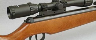
- weapons that can be equipped with IR or NV sights;
- an under-barrel flashlight for hunting instead of night optics, illuminating an area of 100-150 m with a beam (considered no less effective than night vision devices).
A number of characteristics are important for both hunting thermal imagers and HB sights.
Tip : the best thermal imager models can be selected here
It should be remembered that night binoculars for hunting, infrared sights and their analogues are exposed to atmospheric precipitation and even shock loads when fired. Therefore, preference is given to devices that are most protected from moisture, dust, impulse loads, and temperature changes. It’s good if thermal imaging binoculars or a night sight for hunting have the ability to connect external power sources. The charge should last all night without fear that the device will suddenly stop working.
Pay attention to digital zoom (magnifier) if you are going to purchase the appropriate equipment. In devices, the optical component is important, which is responsible for the magnification factor, focusing and field of view. Some night and thermal imaging scopes for hunting have a feature to record the entire process. There may be many additional features - Wi-Fi module, compass, navigator, laser designator. However, the wider the functionality, the higher the cost of the device.
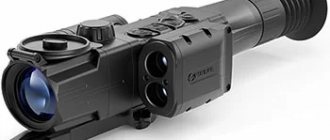
Fact : it is convenient if the equipment is equipped with a rangefinder. Then you can accurately measure the distance between the hunter and his prey. For example, this function is provided in the Pulsar Trail XQ50 , which can be purchased in the online store optics-pro.com.ua .
Best lists
We will highlight the top three leaders in each selected category as a separate TOP, namely:
- Bresser 3×14 – monocular;
- Bresser 3×20 – binoculars;
- Seek Thermal Reveal Pro – thermal imaging.
More details about them:
Bresser 3×14 – monocular
Compact monocular with recording capability from the German company Bresser. Made in a black case made of impact-resistant plastic. It is not afraid of light exposure - there is a digital controller installed on board that controls the strength of the received optical signal at the input of the converter.
Cost: from 14,700 to 17,000 rubles.
night vision device Bresser 3×14
Bresser 3×20 – binoculars
An advanced digital device with a four-inch diagonal LCD display. It has a maximum of six times digital zoom and the ability to record to a MicroSD card.
Price: from 18,990 to 21,000 rubles.
night vision device Bresser 3×20
Seek Thermal Reveal Pro – thermal imaging
The thermal imager is designed and assembled in California, USA. Protected from dust and moisture according to IP 67 standard. The minimum ambient temperature at which the device can operate is minus twenty degrees Celsius.
It will cost from 56,990 to 62,000 rubles.
night vision device Seek Thermal Reveal Pro
Kinds
According to the form factor of the device, the following positions are distinguished:
- Monocular. Mini spyglass. The most affordable option in terms of price/quality ratio. It weighs little and takes up minimal space.
- Binoculars. There are civilian and military purposes. They differ from the previous type by the possibility of binocular (stereo) vision, which increases a person’s viewing angle when working in low light conditions. Typically, the optical system in binoculars has multiple zoom and provides better visibility compared to a monocular.
- Glasses. They are equipped with one converter and one lens, but thanks to parallelization of the signal, a pseudo-stereo image is achieved (the same picture is displayed on both eyes). They are attached with straps to the head and cannot be approached.
- Sights. Structurally they resemble a monocular, but additionally have an aiming reticle, an exposure meter, a system for estimating the distance to an object (optional) and a shank of a certain standard to mount the device on a small weapon.