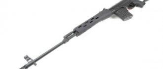
Shotgun Marocchi Si12 12x76 plastic 710mm
Shotgun Marocchi Si12 12x76 plastic 710mm in the World of Hunting online store
The Marocchi Si12 12 gauge smoothbore semi-automatic shotgun combines the functionality and manufacturability of all elements. The semi-automatic machine is reliable and unpretentious in operation.
An important advantage is the light weight of the gun, less than 3 kg. Balance when shooting and easy aiming are ensured. The weight distribution makes it easier to raise the gun, making the movements natural.
An inertial reloading system that uses kinetic recoil energy is efficient in operation and easy to maintain. The barrel is locked using a bolt with a rotating head.
The obvious advantage is the minimum time required to clean the semi-automatic machine. The inertial recharging system, unlike the gas exhaust mechanism, is cleaner and does not leave carbon deposits inside the mechanism. You only need to clean the barrel.
The barrels of Italian Marocchi shotguns are made in-house from chrome-molybdenum steel - the wear resistance of the material extends the service life of the shotgun. Deep drilling method Deep drilling method
— the depth of the hole is more than 10 diameters. In barrel drilling, this ratio is usually equal to or more than 100. More details made it possible to achieve excellent shooting characteristics in terms of sharpness of combat and uniformity of shot spatter.
Chrome plating of the bore prevents corrosion and ensures the durability of the shotgun.
The parts of the inertia shotgun fit perfectly. The Marocci Xi 12's receiver is constructed from high-strength 7075 aluminum alloy, providing structural strength.
Thanks to the hunting rifle's 4-round magazine and semi-automatic reloading, you can quickly fire several shots without changing position.
Marocchi Si12 – balanced and reliable.
The stock and fore-end of Marocci's semi-automatic shotgun are made of a mixture of composite materials - nylon, elastomer and fiberglass in black. The stock is impact-resistant and can withstand negative environmental conditions.
The barrel of the self-loading shotgun is equipped with a ventilated rib. The fiber optic front sight allows you to aim even at dusk. The laconic shape of the handle with notches does not slip and fits perfectly in the hand.
The recoil of the gun is 30% lower than traditional guns of the same weight, thanks to the materials used in the butt and the thick rubber butt pad. The massive bolt and spring are also effective at absorbing recoil felt by the shooter.
The kit includes 5 interchangeable choke tubes that allow you to adjust the shot pattern. This set expands the functionality of the shotgun. The Marocchi Si12 can be used as both a hunting weapon and a sporting shotgun.
The barrel length of 710 mm is used both for running and flying hunts.
Buy shotgun Marocchi Si12 12x76 plastic 710mm
You can in the World of Hunting online store, or in the gun stores of our network in Moscow, St. Petersburg and other cities of Russia.
Description
Structurally, the IS is an automated operator workstation and eight instrument cabinets of a data acquisition system (hereinafter referred to as DAC) with modules of PXI, SCXI and LXI standards installed in them, connected by an Ethernet local network:
— thermal station cabinet — installed in the test box. Equipment for collecting, processing and transmitting temperature information is installed in the cabinet. The cabinet is equipped with a heating and ventilation system to ensure normal operating conditions for the equipment installed in it;
— cabinet of pressure sensors “MIDA” — installed in the test box. The cabinet contains equipment (pressure sensors) that converts pressure into an electrical signal. The cabinet is equipped with a heating system to ensure normal operating conditions for the equipment installed in it;
— cabinet of pressure sensors “ZOND” — installed in the test box. The cabinet contains equipment (pressure sensors) that converts pressure into an electrical signal. The cabinet is equipped with a heating system to ensure normal operating conditions for the equipment installed in it;
— crossover cabinet No. 1 — installed in the control room. The cabinet contains four vertical rows of DIN rails with terminals and semiconductor relays. There is also space for installing an automatic control and control unit (BARC) of the engine;
— crossover cabinet No. 2 — installed in the control room. The cabinet contains two vertical rows of DIN rails with terminals. Rotating frames are used to install power supplies for pressure sensors. There is also space for installing engine control lever (EC) equipment;
— synchronization cabinet — installed in the generator room. The cabinet contains equipment that generates the entire IC clock frequency and reference time, and an uninterruptible power supply system;
— instrument cabinet No. 1 — installed in the control room. The cabinet contains the following equipment: SSD No. 1, parameter server, KVM-8 switch, UPS uninterruptible power supply unit and D-link switch;
— instrument cabinet No. 2 — installed in the control room. The cabinet contains the following equipment: SSD No. 2, SSD No. 3, UPS uninterruptible power supply unit.
An automated operator workstation is installed in the control room.
The principle of operation of the IS is based on measuring the parameters of turboshaft engines on stand 18 (TVaD) with sensors of physical quantities, converting them into electrical signals, converting electrical signals into digital code using SSD and transferring digital information to the personal computer IS (PC) for its further use in automated testing process control system (ASUTP-I).
Functionally, the system consists of measuring channels (IC):
IR rotor speed and AC frequency;
IR temperature (with thermoelectric converters XA, XK) and DC voltage corresponding to the temperature values;
IR temperature (with TSP resistance thermometers) and DC resistance corresponding to temperature values;
IR pressure and DC current corresponding to pressure values;
IR torque force;
IR fuel consumption;
IR oil flow (pumping);
IR vibration parameters and DC voltage corresponding to the vibration parameter values;
IR angular displacement and DC voltage corresponding to the angular displacement values;
IR time intervals.
IR Rotor Speed and AC Frequency The operating principle of IR Rotor Speed is based on the law of electromagnetic induction. Each time a “tooth” of the inductor gear passes near the end of the permanent magnet of the sensor, an induced emf is generated. Pulse signals are sent to the SSD, where they are converted into a digital code that is registered in a PC, where the program calculates the value of the rotor speed.
The principle of operation of the IR AC frequency is based on the conversion of the frequency into a digital code in the SSD, followed by calculation of the measured frequency using a PC program.
IR temperature (with thermoelectric converters XA, XK) and DC voltage corresponding to the temperature values
The operating principle of IR temperature is based on the dependence of the thermo-EMF that occurs in thermoelectrode wires on the temperature difference between the “hot” and “cold” junctions.
The principle of operation of IR voltage is based on the conversion of thermo-EMF SSD into a digital code, calculating the temperature according to the nominal calibration characteristic, taking into account the temperature of the cold junction.
IR temperature (with RTD thermometers) and DC resistance corresponding to temperature values
The principle of operation of IR temperature is based on the dependence of the change in the resistance of the thermometer on the temperature of the medium. The DC resistance value corresponding to the temperature values is sent to the SSD, where, according to the nominal calibration characteristic, it is converted into a digital code and further transmitted to the PC.
The principle of operation of IR resistance to direct current, corresponding to temperature values, is based on the conversion of the resistance into a digital code in the SSD, followed by calculation of the measured resistance using a PC program.
IR pressure and DC current corresponding to pressure values
The principle of operation of IR pressure is based on the dependence of the output signal of pressure sensors on the values of movement or deformation of the sensitive element of the sensor caused by the influence of the measured pressure.
The operating principle of IR DC power is based on converting the SSD output signal of the pressure sensor (DC power) into a digital code, registering it in a PC, and then calculating the values of the measured pressure using a known calibration characteristic.
IR torque force The operating principle of IR is based on the influence of torque force through the tandem hydraulic brakes HS 150 on the strain gauge force meter, as a result of which the strain gauge bridge becomes unbalanced. The output signal, proportional to the applied torque, is sent to the SSD, where it is converted into a digital code recorded by the PC.
IR fuel consumption
The operating principle of the IR is based on the indirect measurement of mass fuel flow using the electrical signal from volumetric flow and fuel density converters. The mass fuel consumption is determined using a PC program.
IR oil flow (pumping) The operating principle of IR oil flow (pumping) is based on measuring the volumetric oil flow rate using TPR turbine volumetric flow converters. Electrical signals from the TPR are sent to the SSD, where, taking into account the time interval, the oil consumption (pumping) is programmed.
IR vibration parameters and direct current voltage corresponding to the values of vibration parameters. The operating principle of IR is based on the use of piezoelectric vibration sensors that convert the vibration velocity of the TVaD body into an electric charge supplied to the vibration equipment, from the output of which a direct current voltage corresponding to the vibration velocity at rotor harmonic frequencies is supplied to SSD input, where it is converted into a digital code and transmitted to a PC with subsequent calculation of the parameters of the measured vibration.
IR angular displacement and DC voltage corresponding to the values of angular displacement The operating principle of IR angular displacement is based on the conversion, using a tracking system, of the angle of rotation of the engine elements into a direct current voltage proportional to them.
The operating principle of the IR DC voltage corresponding to the angular displacement values is based on converting the DC voltage corresponding to the angular displacement values into a digital code using an SSD and transmitted to the PC, where it is converted into an angle value.
IR time intervals The operating principle of IR is based on counting the number of pulses generated by the SSD during the time between two edges of external discrete signals. The number of pulses counted by the SSD is converted into a time interval value and transmitted to the PC.
According to the operating conditions, the ICs meet the requirements of gr. 1.1 climatic modification UHL in accordance with GOST RV 20.39.304-98 with a range of operating temperatures from 10 to 30 ° C and relative air humidity from 30 to 80% at a temperature of 25 ° C, without requirements for mechanical stress, precipitation, or special environments.
The appearance of the instrument cabinets is shown in Figures 1-7.
The appearance of the automated operator workstation and the place for stickers are shown in Figure 8.
Protection against unauthorized access is provided in the form of special locks on cabinet doors, locked with keys (Figures 6, 7).
Verification
Carried out in accordance with the document “Measuring system SI-ST18 for measuring the parameters of turboshaft engines at stand 18. Verification methodology 061.115.2010 MP”, approved by the head of the GCI SI FGU “32 GNIIII Ministry of Defense of Russia” on June 01, 2011.
Basic means of verification:
— portable pressure calibrator Metran-501-PKD-R (registration No. 22307-04): pressure reproduction range from minus 0.1 Pa to 60 MPa, limits of permissible reduced pressure reproduction error ± (0.04 - 0.05)% ;
— calibrator-meter of standard signals KISS-03 (registration No. 20641-00): range of reproduction of DC voltage from 0 to 100 mV, limits of permissible error of reproduction of DC voltage ± (0.05+0.0075-(i/CC -1)) %, where U is the upper limit of the DC voltage reproduction range, V, IR is the specified value of the DC voltage reproduction, V;
— Fluke 500 series temperature calibrator, model 518 (registration No. 22247-01): temperature reproduction range from minus 30 to 1000 °C, temperature reproduction error limits ± 0.25 °C;
— resistance store P4831 (reg. No. 38510-08): DC resistance reproduction range from 0.001 Ohm to 111111.10 Ohm, accuracy class 0.02;
— low-frequency precision signal generator G3-110 (registration No. 5460-76): frequency reproduction range from 0.01 Hz to 2 MHz, limits of permissible frequency reproduction error ± 5 10-5;
— glass hydrometer for oil ANT-1 (reg. No. 28386-04): measurement range from
3 3
750 to 830 kg/m, permissible absolute error limits ± 0.5 kg/m;
— programmable calibrator P320 (reg. No. 7493-79): DC voltage reproduction range from 0 to 10 V, limits of permissible absolute error in DC voltage reproduction ± (10-ik + 40) µV, where IR is the specified value, mV; range of reproduction of direct current strength from 0 to 100 mA, limits of permissible error in reproduction of direct current strength ± (0.11k + 1) µA, where 1k is the specified value, mA;
— optical dividing head ODGE-20 (reg. No. 26906-04): flat angle measurement range from 0 to 360°, limits of permissible absolute error in flat angle measurements ± 20″;
— arbitrary waveform generator Agilent 33210A (reg. No. 32993-09): frequency reproduction range from 1 μHz to 20 MHz, limits of permissible frequency reproduction error ± 2 10-5%;
— weights 10 kg, accuracy class M1 (registration No. 30010-05): limits of permissible mass deviation ± 0.5 g.

