Technical description and interpretation of error P000A
This diagnostic trouble code (DTC) is a generic powertrain code. The P000A code is considered a common code because it applies to all makes and models of vehicles. Although the specific repair steps may vary slightly depending on the model.
Many modern cars use variable valve timing (VVT) to improve engine performance and fuel economy. In a VVT system, the powertrain control module (PCM) controls the solenoid-controlled oil control valves.
These valves apply oil pressure to an actuator located between the camshaft and the drive chain sprocket. In turn, the actuator then changes the angular position or phase change of the camshaft. The camshaft position sensor is used to monitor the position of the camshaft.
The camshaft position slow response code is set in the following case. When the actual camshaft position does not match the position required by the PCM during camshaft timing changes.
Regarding the description of fault codes, the letter "A" represents the intake, left or front camshaft. On the other hand, "B" stands for exhaust, right or rear camshaft. Bank 1 is the side of the engine that contains cylinder #1, and Bank 2 is the opposite side. If the engine is in-line or straight-line, then there is only one bank.
Code P000A sets when the PCM detects a slow response to camshaft position change from Bank 1 "A" circuit. This code is associated with P000B, P000C and P000D.
Description and meaning of error P000B
This generic powertrain diagnostic trouble code (DTC) typically applies to all OBD-II vehicles equipped with variable valve/cam timing. This may include, but is not limited to vehicles from Subaru, Dodge, VW, Audi, Jeep, GMC, Chevrolet, Saturn, Chrysler, Ford, etc. Although general, the exact repair steps may vary depending on the make/model. Many modern vehicles use variable valve timing (VVT) to improve engine performance and fuel economy. In a VVT system, the powertrain control module (PCM) controls the solenoid-operated oil control valves. These valves apply oil pressure to an actuator mounted between the camshaft and timing sprocket. In turn, the drive changes the angular position or changes the phase of the camshaft. The camshaft position sensor is used to monitor the position of the camshaft. A slow camshaft position response code is set when the actual camshaft position does not match the position commanded by the PCM when the camshaft timing changes. As it relates to fault code descriptions, a indicates the intake, left or front camshaft. On the other hand, B means exhaust, right or rear camshaft. Bank 1 is the side of the engine containing cylinder #1, while bank 2 is the opposite bank. If the motor is an inline or direct design, there is only one bank. The P000B code sets when the PCM detects a slow response when changing the camshaft position phase from the Bbank 1 circuit. This code is associated with P000A, P000C and P000D.
Diagnosis and problem solving
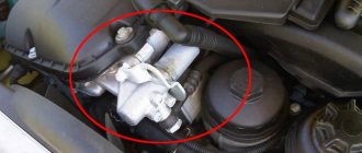
Start by checking the level and condition of your engine oil. If the oil is normal, perform a visual inspection of the camshaft position sensor. As well as the oil control solenoid and related wiring.
Look for loose connections, damaged wiring, etc. If damage is found, repair, erase the code and see if it comes back. Next, check technical service bulletins (TSBs) regarding P000A. If nothing is found, you will need to proceed to step-by-step system diagnostics.
The following is a generalized procedure as testing this code varies from vehicle to vehicle. To accurately check the system, you need to refer to the manufacturer's diagnostic flow chart.
Inspect the camshaft position sensor
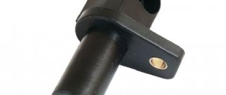
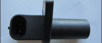
Most camshaft position sensors are Hall sensors or permanent magnet sensors. There are three wires connected to the Hall effect sensor: reference, signal and ground. A permanent magnet sensor will only have two wires: signal and ground.
Hall Sensor:
Determine which wire is the signal return wire. Then connect the DMM to it using a test lead with a probe. Set the digital multimeter to the constant voltage position.
Connect the black wire of the meter to ground. Crank the engine - if the sensor is working correctly, you should see fluctuations in the readings on the meter. Otherwise, the sensor is faulty and must be replaced.
Permanent magnet sensor:
Remove the sensor connector and attach a digital multimeter to the sensor terminals. Set the DMM to AC voltage and crank the engine. You should see the voltage fluctuate. Otherwise, the sensor is faulty and must be replaced.
Diagnose the camshaft sensor circuit
Hall Sensor:
Start by checking the circuit's ground. To do this, take a digital multimeter set to constant voltage. Connect between the battery positive terminal and the sensor ground terminal on the harness side connector.
If there is a good ground, you should get a reading of around 12 volts. Next, check the 5-volt reference side of the circuit. Connect between the negative terminal of the battery and the reference sensor terminal on the harness side of the connector.
Turn on the car's ignition. You should see a reading of about 5 volts. If either of these two tests does not give satisfactory readings, the circuit must be diagnosed and repaired.
Permanent magnet sensor:
Check circuit grounding. To do this, take a digital multimeter set to constant voltage. Connect between the battery positive terminal and the sensor ground terminal on the harness side connector.
If there is a good ground, you should get a reading of around 12 volts. Otherwise, the circuit will need to be diagnosed and repaired.
Check Oil Control Solenoid
Remove the solenoid connector. Use a digital multimeter set to ohms to check the internal resistance of the solenoid. To do this, connect a meter between the solenoid B+ terminal and the solenoid ground terminal.
Compare the resistance measurement with the factory repair specifications. If the meter shows readings out of specification. Or outside the limits (OL), indicating an open circuit, the solenoid should be replaced. It's also a good idea to remove the solenoid to visually check the screen for metal debris.
Test Oil Control Solenoid Circuit
Check the power side of the circuit:
Disconnect the solenoid connector. With the vehicle's ignition on, use a digital multimeter set to constant voltage. To check for power to the solenoid (usually 12 volts).
To do this, connect the negative lead of the measuring device to the negative terminal of the battery. A positive meter lead to the solenoid B+ terminal on the harness side of the connector. The multimeter should show 12 volts. Otherwise, the circuit will need to be diagnosed and repaired.
Check the ground side of the circuit:
Remove the solenoid connector. With the vehicle's ignition on, use a digital multimeter set to constant voltage to check the ground. To do this, connect the positive lead of the measuring device to the positive terminal of the battery. And the negative lead of the meter, to the solenoid ground terminal on the harness side of the connector.
Command the solenoid ON using an OEM equivalent scan tool. The multimeter should show 12 volts. If not, the circuit will need to be diagnosed and repaired.
Check timing chain and VVT drives
If everything has been checked up to this point, the problem may be with the timing chain, or VVT drives. Remove the necessary components to gain access to the timing chain and actuators.
Check the chain for excess play, broken guides or tensioners. Check the drives for visible damage, such as worn teeth.
Other possible errors in Ford Focus 3
During the operation of the car, the appearance of various errors is inevitable, preventing normal spending of time behind the wheel. The ECU acts as the main processor of all major microprocesses. Any malfunction in the transmission, exhaust gas control system, ignition system and other important components in the vehicle system can result in a serious breakdown, the elimination of which will take a lot of time and require significant financial waste. We looked at the main and most common errors found in the third generation Ford Focus. But there are other errors that, although not often, also worry car owners:
- P0014 – problem with the exhaust camshaft valve timing control; it is necessary to unscrew the inlet solenoid valve and thoroughly clean it of metal shavings and other inclusions;
- F006-16 – the voltage in the circuit has dropped below the threshold level; check the battery charge level, install a new battery;
- P0606 – error in communication between the module and the control unit, can be eliminated by changing the firmware;
- P073F – transmission error, requires detailed diagnostics using Ford IDS;
- P0884 – intermittent signal from the TCM control unit;
- P2701 – malfunction of the friction elements of the gearbox;
- P0902 – TCM malfunction, comprehensive Powershift diagnostics using Ford IDS is required;
- P087A, P0805 – violation of the electrical circuit of the clutch position sensor;
- U0100 – loss of communication with the ECU; first of all, you need to check all the wiring, all the wires and “chips” going to the block;
- P07A3 – friction elements jamming when turned on;
- P2119 – violation of convergence of remote sensing signals; cleaning the damper, replacing the unit;
- U0428-64 – steering wheel position sensor is faulty;
- C401_64 – bad signal from the ECU; diagnostics should consist of checking the battery charge, visual inspection of contacts, control unit chips, which can be removed using Ford IDS;
- P1712 – reduction of torque in the transmission; there may be problems with the wiring, with the ECU or the box control module;
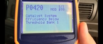
- P0420 – incorrect operation of the catalyst; diagnostics and replacement of the device;
- P0606 – the CU module malfunction can be eliminated by updating the firmware;
- P2837 – transmission fork “B” error;
- C422_64, U0415 – incorrect data received from the control module; diagnostics of all wiring of the unit is required;
- P287B – shift fork calibration not registered; need to inspect the box control module;
- P0521 – malfunction with the oil pressure sensor; checking and replacing the device;
- P0702 – problem in the electrical part of the gear shift mechanism;
- P0365 – camshaft position sensor circuit “B” is faulty, circuit – 1;
- P087b – clutch position sensor “B”; check the sensor itself and all supply wiring;
- U2005 – error in receiving speed data; often resolved by replacing the speed sensor;
- U1007 – loss of communication with the battery monitoring sensor;
- P0805 – incorrect position of the clutch, possibly jammed;
- 1706_00 – open circuit in the transmission speed switch;
- P090c – insufficient signal level in the clutch drive;
- U0073 – problem with the CAN data bus; inspect the connectors of the control unit and instrument panel;
- P0030 – heater power supply interruption (oxygen sensor);
- P2872 – clutch “A” is stuck in the engaged state;
- P0607 – incorrect performance characteristics of the box control module.
Information errors are eliminated by resetting them to the Ford Focus 3. They do not have any effect on the operation of the engine, control unit and the entire electronic part of the vehicle. Errors caused by malfunction of key machine components cannot be ignored. They are a signal that important car systems are not working properly, which affects the safety, comfort, economy, dynamism and other important distinctive characteristics of the Ford Focus 3.
On which cars is this problem most common?
The problem with code P000A can occur on different machines, but there are always statistics on which brands this error occurs more often. Here is a list of some of them:
- Audi (Audi a4, Audi A5, Audi q5)
- Chevrolet (Chevrolet Cruze)
- Chrysler
- Citroen (Citroen C4, Berlingo)
- Dodge
- Ford (Ford Mondeo, Focus)
- Jeep
- Opel (Opel Insignia)
- Peugeot (Peugeot 307, 308, 408)
- Porsche
- Saturn
- Skoda (Skoda Octavia)
- Subaru
- Toyota
- Volkswagen (Volkswagen Golf, Jetta, Passat, Tiguan)
With fault code P000A, you can sometimes encounter other errors. The most common are the following: P0011, P0016.


