Recently, crossovers, or so-called SUVs, have become increasingly popular. These cars differ from real SUVs not only in the absence of a supporting frame (here this function is performed by the body), but also in “dishonest” all-wheel drive with electronic locks. Moreover, it connects automatically. To connect the two axles together, a viscous coupling is used. Not every motorist knows what this element is. In today's article we will look at this mechanism in more detail.
How it works
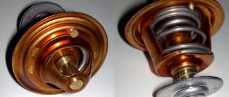
The operating principle of a viscous cooling fan coupling is directly related to its structure.
Thanks to these features, the fan does not operate constantly, but depending on the temperature of the coolant. This allows the cooling system to operate as efficiently as possible. The viscous coupling itself consists of a non-separable oval-shaped body. There are two disks inside it. One of them is rigidly mounted on the fan impeller shaft. The other is mounted on a shaft connected to the drive. The discs are in a viscous silicone liquid, which is also located in a small reservoir. The design also includes a bimetallic plate. This system works as follows. At normal air temperatures, the discs are either a short distance apart or slightly interlocked. In any case, one slips relative to the other. In this position the fan does not work.
An increase in temperature leads to the fact that the bimetallic plate, compressing, bends, squeezing liquid out of the reservoir. As a result, the pressure on one of the discs increases. It presses against the fan impeller disk and begins to spin it. The higher the temperature, the tighter they are pressed and the less they slip. When the temperature decreases, the plate returns to its original position. The pressure inside the chamber returns to normal and the fan stops.
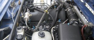
The viscous coupling is installed together with the fan on the pump shaft. Sometimes this design can be seen on the crankshaft, it all depends on the layout of the given car model. A fan with a viscous coupling is much more efficient than a simple impeller mounted on a shaft. After all, it works as needed, without cooling the engine, for example, when warming up in winter. Most often, fans with viscous couplings are installed on cars that constantly operate under load:
- SUVs;
- Crossovers;
- Sports cars;
Trucks.
This is due to more efficient cooling in all conditions.
What kind of liquid
It is located in a closed device housing called a viscous coupling. What it is? Inside the coupling there is a dilatant liquid, which is made on the basis of silicone.
Has special properties. In a calm state it is liquid. But as soon as the molecules are mixed, it changes its density. Dilatant liquid is filled in for the entire service life of the mechanism.
Role in the internal combustion engine cooling system
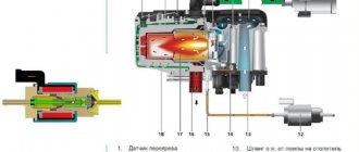
The operating principle of a viscous cooling fan coupling.
interesting theory A viscous coupling fan is installed on cars with a longitudinal engine (usually all-wheel drive and rear-wheel drive models). With this arrangement, it is most advisable to connect the radiator fan pulley to the water pump pulley. As you know, rotation of the water pump is transmitted by a service belt from the crankshaft pulley.
The disadvantage of this design is that the rotation speed of the fan impeller will always be proportional to the crankshaft speed. Such a device will result in the engine being excessively cooled at high speeds in cold air conditions, which will reduce its efficiency. In addition, the permanent connection of the impeller and the crankshaft pulley will increase mechanical friction losses, which will take away power and increase fuel consumption.
Device
The difference in the design of viscous fan couplings for Toyota, BMW, Mercedes, Audi. is minimal, since they are all designed and work according to the same principle.
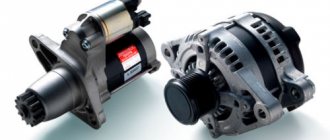
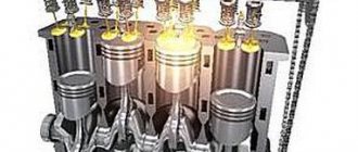
A shaft with a connecting flange is attached to the cooling pump drive, so its rotation speed is always proportional to the crankshaft speed. A drive pulley, in turn, is attached to the shaft, which rotates in the working chamber. The working and backup chambers are separated by plates. The transition between chambers is only possible through inlet valves and return passages. Initially, the backup chamber is filled with special silicone oil. The drive pulley, or disk, as it is also called, has oblique teeth around its circumference, which, when rotated, allow the oil to be expelled back into the reserve chamber. The surface of the drive disks, like the dividing plates, has special ribs that turn the working chamber into a kind of network of labyrinths through which silicone oil circulates.
The coupling housing, to which the fan impeller is attached, is connected to the shaft (viscous coupling rotor) via a conventional ball bearing. The inlet valves are connected to a bimetallic plate, which is located in front of the viscous coupling housing. When heated, the plate expands, which leads to an increase in the flow area of the valves.
Properties of silicone oil
The main feature of silicone fluid used in viscous fan couplings is heat resistance and viscosity stability. As temperature changes, the oil changes its viscosity only slightly.
Some sources indicate that with increasing temperature, the oil expands, which provokes viscous engagement of the drive disk with the viscous coupling body. This understanding of the operating principle of a viscous cooling fan coupling is false and most likely arose due to a comparison of the viscous fan coupling with viscous couplings of transfer cases of all-wheel drive vehicles. Viscous differential couplings use a dilatant fluid whose viscosity is highly dependent on the rate of shear strain.
Principle of operation
When the working chamber is not filled with oil, the drive disk rotates freely in the working chamber. A small amount of oil is still present, but the coefficient of adhesion between the drive pulley and the viscous coupling housing is minimal, so as the engine speed increases, the rotation speed of the impeller does not increase.
The process of warming up the engine and increasing the temperature of the antifreeze in the radiator is accompanied by heating of the bimetallic plate. When heated, the plate expands, which leads to the opening of the inlet valve and an increase in the amount of working fluid penetrating from the reserve into the working chamber. The friction that occurs between the drive disk and the separating plates leads to an increase in the speed of rotation of the housing and the fan impeller.
When the engine needs maximum cooling, the bimetallic strip is bent to provide maximum flow area to the intake valves. In this case, the difference in the rotation speed of the shaft and the viscous coupling housing is minimal, so an increase in the crankshaft speed leads to an almost equivalent increase in the rotation speed of the fan impeller.
Functionality check
Checking the viscous fan coupling is not difficult. According to the vehicle operating instructions, this must be done first on a cold internal combustion engine, and then after it reaches operating temperature. Here's how the mechanism works in these modes:
- Cold system . The engine is running, the driver briefly increases the engine speed several times. A working device will not transmit torque to the impeller, since the outlet must remain open and there is no interlocking between the discs.
- Hot system . In this case, depending on the temperature of the antifreeze, the shutoff of the drain circuit will depend, and the fan will rotate slightly. The revs should increase when the driver presses the gas pedal. At this moment, the engine temperature rises, the pump drives hot antifreeze along the line to the radiator, and the bimetallic plate is deformed, blocking the drainage of the working fluid.
The mechanism can be checked independently without diagnostics at a service station in the following ways:
- The motor doesn't work. Try to rotate the fan blades. There should be some resistance felt. The fan should not rotate by inertia;
- The engine starts. A slight noise should be heard inside the mechanism for the first few seconds, which gradually subsides due to some filling of the cavity with the working fluid.
- After the engine has been running for a while, but has not yet reached operating temperature (the thermostat is not open), the blades will rotate slightly. We roll a sheet of paper into a tube and insert it into the impeller. The fan should lock, but there should be some resistance.
- The next step involves dismantling the coupling. The device is immersed in boiling water to heat up its internal parts. An attempt to rotate the blades should be accompanied by resistance from the mechanism. If this does not happen, it means that there is not enough viscous substance in the coupling. During this work, you can additionally dismantle the heat exchanger of the cooling system and wash it.
- Check for longitudinal play. In a working mechanism, this effect should not occur, since a constant gap must be maintained between the disks. Otherwise, the mechanism needs to be repaired or replaced.