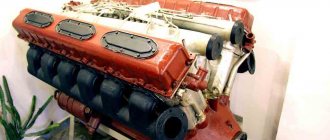
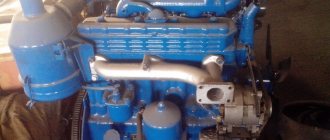
The four-cylinder 4-stroke diesel engine D 240 is air-cooled and has direct fuel injection. This power unit was installed on the MTZ 80 tractor and enjoyed well-deserved love among car owners.
The reliable, maintainable, powerful and easy-to-use motor lasted on the assembly line for several decades and is also found on MTZ tractors today.
Specifications
Download .xls file
xls
Download picture
Send by email
| OPTIONS | MEANING |
| Cylinder block material | cast iron |
| Supply system | Direct injection |
| Type | in-line |
| Working volume, l | 4.75 |
| Power, l. With. | 80 |
| Number of cylinders | 4 |
| Number of valves per cylinder | 2 |
| Piston stroke, mm | 125 |
| Cylinder diameter, mm | 110 |
| Compression ratio | 16 |
| Fuel | Diesel fuel |
| Fuel consumption | No more than 238 liters per hour |
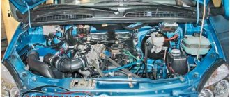
The engine was installed on the MTZ 80 tractor and its modifications.
Repair of tractor MTZ-80
How much does a VAZ 2110 engine weigh, 8 valves assembled?
Experts and users note that tractors of the Belarus family are distinguished by their amazing maintainability. This largely explains their popularity among Russian consumers. Machine repairs, in most cases, can be done on site. Spare parts and service fluids are cheap and accessible.
The unpretentious motor will cause a minimum of inconvenience. The main faults are related to the gearbox. To replace parts or troubleshoot problems, you can use professional forums. Over its long history, the MTZ-80 has managed to reveal all its few weaknesses. Therefore, repairing equipment will not cause difficulties.
Description
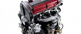
This is a classic four-cylinder modification of a diesel engine, which has a reinforced cylinder block, and thanks to the presence of air cooling, its design is significantly simplified. This naturally aspirated power unit is highly reliable and easy to maintain. Its maintainability allows repairs to be carried out even in the field.
Due to the presence of direct fuel injection, the engine provides the necessary traction and excellent power characteristics. The motor has an electric starter, which significantly simplifies the operation of the MTZ-80 tractor in the winter, when problems with starting a diesel engine could be observed.
Another design feature of this engine is an undivided combustion chamber, as well as the formation of a volume-film working mixture. In this case, the inlet of the fuel mixture into the combustion chamber is carried out as follows. Part of the fuel is sprayed into the maximum possible volume of the combustion chamber, while the other part spreads over the surface of the cylinder, creating the necessary thin film. As a result of such technologies, the maximum possible power and efficient combustion of fuel are ensured, which has improved the dynamic characteristics of this power unit.
The combustion chamber itself has an original spherical shape, which improves the mixing of air and fuel, forming vortex air flows inside the combustion chamber. The power of the D 240 engine is 80 horsepower, which is achieved at 2200 crankshaft revolutions per minute. At the same time, the engine is characterized by proper throttle response, guaranteeing the tractor the necessary power and traction.
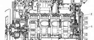
The D 240 cylinder block was cast from high-strength gray cast iron. The use of such material allows you to completely avoid the occurrence of thermal deformations of the power unit when the engine overheats. The cylinder head is attached to the block using 16 extended studs. It should be said that the studs were tightened using a torque wrench, which must be taken into account when performing repair work.
Note that this modification of the engine used a special design of the valve mechanism, which made it possible to protect the valves in the event of a timing chain break. This increased the reliability of the engine, and the engine itself could be operated for a long time without the need for major repairs.
Adjustment procedure
The need to install injection arises when replacing a high-pressure fuel pump (HPF) or installing it after repair, as well as after repairing the piston group of a diesel engine. The adjustment is carried out provided that the fuel equipment, injection pump and the adjusted gas distribution mechanism of the diesel engine are in good working order. The installation process consists of the sequential operations described below.
Installing the first cylinder on the compression stroke
On the right side, in the direction of travel of the machine, in the wall of the engine mounting to the clutch housing, above the longitudinal beam of the tractor frame near the oil filler neck, there is an installation dipstick. With its short threaded part it is screwed into the mounting wall and with its long threadless part it is installed outside. If it is necessary to install the first cylinder in the “compression” stroke position, the dipstick is installed in the hole, resting its long part against the engine flywheel. Slowly turning the diesel crankshaft, find the position at which the probe will fall into the hole on the flywheel and enter the body of the part completely by 4-5 cm
It is important not to confuse the installation hole with the technological, balancing drillings of the flywheel, which are much shallower in depth. The found position corresponds to an advance of 26 ̊ before the piston of the first or fourth cylinder approaches TDC
This position corresponds to the technical requirements of D 240 for setting the start of fuel injection into the cylinder during the “compression” stroke. To determine which of the cylinders in the first or fourth the “compression” stroke has begun, you need to remove the valve cover. A pair of closed valves will indicate in which of the two cylinders (first or fourth) the “compression” stroke has begun.
Installation probe for D 240
Disconnecting the pump drive
To establish synchronization of the engine and fuel injection pump operating cycles, you need to understand that the pump drive connecting through the engine timing gears must be disconnected. The drive is connected by connecting the holes of the pump drive gear 4 with the adjusting holes of a special washer 5 along the perimeter through a splined bushing fixed to the pump shaft. Access to the drive is achieved by opening the front cover 8 of the pump. To disconnect, unscrew two fastening bolts 3 with strip 7 and remove the adjusting washer from the splined sleeve. In this position, the rotation of the shaft cranks will not be transmitted through the camshaft gear drive to the pump shaft 6.
Injection pump drive device D 240
Momentoscope installation
After identifying the cylinder in the “compression” stroke and disconnecting the drive on the fuel pump, install a torque scope on the corresponding supply section of the pump instead of the high pressure pipeline connecting the section to the cylinder injector. To more accurately determine the beginning of the injection moment, set the manual fuel supply lever to the maximum position. To determine the moment of injection, if necessary, pump the fuel equipment with a manual pump pump, removing air from the system.
Injection installation operations
Determining and setting the timing of fuel supply
By turning the injection pump camshaft clockwise and observing the fuel level in the device tube, you need to determine the position of the pump shaft at the moment fuel supply begins in this section. The moment the supply begins will be the position at which the fuel level in the device tube begins to rise, shifting as a result of the start of the supply cycle, running the injection pump shaft cam onto the plunger pusher of the corresponding section
It is very important to determine, by observing the fuel level in the momentoscope, the beginning of this cycle
Setting the position of the pump drive shim
Having determined the moment of the start of injection on the section by the position of the injection pump shaft, connect the pump drive by installing a splined adjusting washer on the splined bushing. The fastening bolts with the strip are screwed into the most aligned holes of the washer and the flange of the pump drive gear. In this case, the bolts should fit freely without snagging. Then install the pump cover by tightening the three bolts around the perimeter of the cover. The axial clearance of the drive gear is adjusted using the adjusting central screw in the cover. To do this, unscrew the lock nut of the screw, screw it all the way into the washer bar and unscrew it 1/3 or 1/2 turn, after which the position is fixed with a lock nut.
Malfunctions
| FAULT | REMEDY METHODS |
| The engine has significantly lost power and reacts poorly to pressing the gas pedal. | The cause of such a breakdown may be the failure of the fuel pump, which does not provide the necessary pressure in the system. |
| A pronounced metallic knock appeared over a wide speed range. | We recommend opening the engine and adjusting the valves. Such service work should be carried out every 50 thousand kilometers of the engine. |
| Significant oil leaks appeared. | Engine oil can leak either from under the valve cover or through an oil filter that has lost its seal. It is necessary to localize the location of the leak and, depending on its location, carry out appropriate repairs. |
| The motor vibrates a lot. | Check the condition of the engine mounts, which are the weak point of this engine. If there is a problem with such pillows, the motor must be replaced. |
Features of valve adjustment
Minsk plant tractors are equipped with MTZ D 240 engines. This is a powerful four-cylinder diesel unit with a capacity of 80 hp. With. with an undivided combustion chamber of the combustible mixture. Less common are twelve-cylinder units produced by the Yaroslavl Motor Plant (YaMZ). The valve adjustment on these engines is not fundamentally different from other domestically produced diesel units.
Rocker arm and valve clearances are checked every 480 hours of operation, as well as after any repair or removal of cylinders. The gaps on a cold engine should be no more than 0.25 mm.
Adjustments must be made at certain intervals
Valve adjustment procedure
There are different ways to adjust the valves on the MTZ 82. They differ in the method of searching for TDC (highest dead center), at which it is necessary to check and adjust. TDC can be determined by the appearance of fuel in the cylinders or by the valve pressing into the piston when pressed (the stroke should be about 10 mm). Some craftsmen place marks on the crankshaft pulley or are guided by the hole in the plate and the position of the flywheel.
However, it is easier and more reliable to follow the manufacturer’s instructions and adhere to this order:
- Crank the crankshaft until the intake valve of the first cylinder begins to open and the exhaust valve begins to close. This is easy to track visually.
- Adjust the gaps in valves No. 4, 6, 7 and 8, counting from the fan.
- Turn the crankshaft one more revolution until the fourth cylinder closes. After this, adjust the gaps in the remaining valves (1, 2, 3 and 5).
Adjusting valves with cylinder head broaching
Broaching is an important procedure that maintains a reliable connection between the head and cylinder block, which protects the engine from oil leaks and ensures its normal operation. On modern engines, special spring bolts are installed that maintain the required tightening torque. But on D 240 type engines, it is advisable to carry out this operation for preventive purposes, combining it with valve adjustment and any repairs to the cylinder head.
Tightening control is performed only with special torque wrenches. The order of tightening the head is standard - first the central nuts, then the rest according to the “crosswise” principle. The cylinder head tightening torque is 150–170 Nm. Insufficient torque indicates that the bolt is not strong enough and may break. This bolt needs to be replaced. In the opposite situation, the bolt must also be replaced as having increased strength
This is important because the cylinder head bolts operate in a “heating-cooling” mode and need special attention
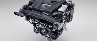
Tuning
It is possible to increase the power of the power unit to about 100 horsepower by installing a turbine and a new fuel supply system on the D 240 engines.
In specialized stores you can find a ready-made conversion kit for a turbine, which includes the necessary fasteners, the turbocharger itself, a new oil and fuel pump. Such tuning will significantly increase the power of the power unit with virtually no loss of engine reliability.
Engine D240
What to do if your diesel engine stalls
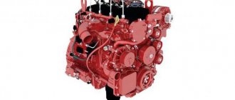
The D240 is a powerful engine that began to be produced at the Yaroslavl Motor Plant in the early 1970s. The power of different versions ranged from 360 to 800 hp, which in turn was ensured by the presence of 12 cylinders, with a diameter of 13 cm and a piston stroke of 14 cm.
The D 240 engine was also produced at the Minsk Tractor Plant. The difference from YaMZ engines was manifested in a smaller number of cylinders, as well as in their smaller diameter and shorter piston stroke.
- High power
- Durability (with proper care and timely maintenance)
- Long-life crankshaft main bearings
- The presence of a fluid coupling as a cooling fan drive
- No cylinder head cracks
- Difficulty of repair
- Major repairs require a large number of spare parts
- Cost of spare parts for overhaul
- High fuel consumption
Like other similar engines, the YaMZ D 240 engine consists of a gas distribution and crank mechanisms, as well as:
- Cooling systems
- Lubrication system
- Launch systems
- Power systems
Basic systems of the D 240 engine
Cooling system
The D 240 motor is equipped with a closed liquid cooling system, which contacts the environment only through a valve. The system consists of a radiator, water pump, thermostat, fan, cooling jacket and various pipes for supplying and discharging coolant.
Lubrication system
The D 240 engines presented by both MTZ and YuMZ use a single-circuit lubrication system. A special feature is that some parts are lubricated under pressure, the other part - by splashing. The system, in turn, includes an oil intake, pump, centrifuge, radiator, radiator thermostat, as well as bearings and gears for the fuel pump drive.
Supply system
The D 240 engine power supply system is a set of devices that provide not only separate supply of fuel and air, but also the release of waste products. It consists of an air cleaner, manifolds, fuel filters, pump, injectors and low and high pressure pipes. The engine is also equipped with an alternating current generator with a voltage of 14V, which also has a built-in rectifier.
Starting system
The D 240 engines have an electric starter with a power of 4.8 hp. and an electric torch heater, which serves to facilitate engine starting by heating the air admitted into the cylinders. The D 240L engines are started using a starting motor and a gearbox.
A single-cylinder engine with a power of 10 hp is used. It is equipped with a single-mode centrifugal governor, which is installed to maintain a constant frequency of the maximum rotation speed of the HF. To simplify starting in the cold season, a liquid heater is used.