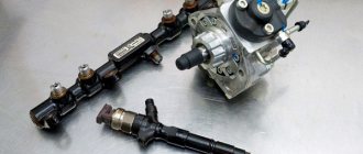
Description of the symbols of the tidy icons
Informational.
The symbols light up green and do not indicate errors - this is only to notify the driver. Yellow warning Error signals. Red lamps warn that there is a critical breakdown in the car.
The explanation of the indicators shown in the photo is given below.
| Number in order | Decoding |
| 1 | Electronic key system fault lamp. Usually not used, the technology is installed only in top versions. |
| 2 | Emergency drop in oil pressure. The user needs to check the lubricant level in the engine. |
| 3 | The fluid level in the brake system expander has dropped below normal. |
| 4 | The airbag is disabled or damaged. |
| 6 | The ESP dynamic stabilization system is disabled or does not work correctly. |
| 7 | The driver's seat belt must be fastened. The lamp often lights up along with an audible signal. |
| 8 | The light indicates that the interior doors or trunk lid are not closed. If everything is in order, you should check the system sensors. |
| 9 | The battery is damaged or will not charge. You will also need to check the generator set. |
| 10/13 | Left and right turn signal indicators respectively. The lights light up simultaneously when the hazard warning lights are turned on. |
| 11 | Empty gas tank indicator, the car needs to be refueled. |
| 15 | The exhaust gas aftertreatment system does not work stably. |
| 16 | The ABS device is broken or unstable. |
| 17 | A tire puncture was found in the car. |
| 18 | Cruise control activated. |
| 19 | The adaptive headlight operating system is disabled or damaged. |
| 20 | Used exclusively on diesel engines. The indicator indicates that the heating of the glow plugs is on. |
| 21/28 | Turn on fog lights for the stern and front, respectively. |
| 22 | The high beam headlights are activated. |
| 23 | Applies only to automatic machines. The indicator indicates that the winter operating mode is turned on. |
| 24 | It is used only on a robot or automatic and indicates that the transmission is switching to sport mode. |
| 25 | Gear engaged indicator. |
| 27 | Pressure dump for the front passenger seat. |
| 29 | Engine warm-up indicator |
| 30 | The interactive suspension control system is disabled or damaged. |
| 31 | Parking sensors are disabled or broken. It also sometimes helps to clean the outdoor sensor. |
| 32 | When the lamp is on, the engine cannot be started. |
| 33 | The side lights are activated. |
| 34 | The oil level in the engine has dropped significantly. It is necessary to immediately replenish the fluid supply. |
| 35 | If the lamp is on, the engine and automatic control system does not work stably. You need to contact a service station. |
The key is on
When the indicator for a car with a key lights up on the dashboard, this may indicate problems in synchronizing the operation of the engine and gearbox. There may also be problems with the units individually. In this case, you will need to come to the service station and perform computer diagnostics to accurately determine the breakdown.
Yellow oil can
Lights up when the oil level in the engine drops. When overcoming bumps or driving downhill, the indicator may flash - this is not scary and happens all the time. A problem is considered when the indicator is constantly on.
Usually it is enough to add oil to the engine and (if any) eliminate leaks.
2.1. Dashboard
| The appearance and location of individual elements in vehicles of various modifications may differ from those shown in the accompanying illustration. |
Location of controls on the vehicle instrument panel
| 1 — Adjuster for tilting the optical axes of the headlights, switches for fog lights and rear fog lights, control for the intensity of the instrument illumination 2 — Switch for controlling the operation of external lighting devices/turning on the instrument illumination 3 — Deflectors of the side air ducts of the interior ventilation/heating system 4 — Left steering column switch for controlling the operation of the indicators turn, headlight mode selection, high beam signaling/tempostat operation control 5 — Icons indicating the horn button 6 — Instrument cluster 7 — Right steering column switch for controlling the operation of glass washers and (if equipped) headlight lenses/on-board processor mode switch 8 — Deflectors central air ducts of the ventilation/heating system 9 — Hazard warning switch 10 — Digital clock/outside temperature meter display/radio/infotainment system/board processor 11 — Radio/infotainment system 12 — Passenger airbag module cover | 13 — Glove box 14 — Control panel for the operation of heating/ventilation/air conditioning systems 15 — Switch for controlling the operation of the electric window drive (Convertible models) 16 — Switches for selecting air circulation modes and turning on the heated rear window 17 — Cigarette lighter/on-board power socket 18 — Glove pocket 19 — Switch for controlling the operation of the electric convertible top (Convertible models) 20 — Ashtray 21 — Ignition switch/steering column lock 22 — Gas pedal 23 — Steering column adjustment control handle 24 — Brake pedal 25 — Clutch pedal 26 — Glove box/fuse mounting block 27 — Lever for releasing the hood latch |
Layout of warning lamps/light indicators and instrumentation on the vehicle dashboard
The arrow indicates the location of the digital display setting button.
Instrument cluster
Warning lamps and indicator lights of the instrument panel
| The completeness of the instrument panel with warning lamps and light indicators depends on the vehicle modification. |
Indicator lamp for automatic adjustment of the angle of inclination of the optical axes of the headlights
| The warning lamp is located on the left side of the instrument cluster above the temperature meter and lights up briefly when the ignition is turned on and should go out a few seconds after the engine starts. Activation of the warning lamp while driving indicates a malfunction of the regulator. To eliminate the causes of failure, contact a car service specialist. |
Supplemental Restraint System (SRS) warning lamp
| This warning lamp is used to alert the driver of failures in the electrical circuits of the SRS supplemental safety systems (airbags, emergency belt tensioners) |
Warning light “Don’t forget to fasten your seat belts!”
| A short-term activation of the warning lamp when the ignition is turned on is accompanied by a sound signal and serves as a warning to the driver and passengers about the need to fasten their seat belts before driving. |
Brake/hydraulic clutch warning lamp
| If the warning light remains on when the ignition is on, check whether the parking brake is fully released. The activation of this lamp may also indicate a drop in the level of the working fluid in the reservoirs of the gas turbine engine or the hydraulic clutch cylinder. |
Electronically controlled engine cooling system warning lamp
| The warning light comes on briefly when the ignition is turned on and should go out a few seconds after the engine starts. Activation of the lamp while driving indicates a malfunction in the engine cooling circuit or air conditioning circuit. The electronic control system automatically switches to emergency operation mode, which allows you to continue driving. Check the coolant level (see Chapter Routine Maintenance). To eliminate the causes of failure, contact a car service specialist. |
Indicator lamp for engine preheating device (diesel models)
| Activation of this warning lamp occurs only when the preheating system of a diesel engine is activated at low ambient temperatures. |
Indicator lamp for electronic engine control systems/automatic transmission/start interlock
| The warning light comes on briefly when the ignition is turned on and should go out a few seconds after the engine starts. Failure of the lamp to turn off indicates a malfunction in the electronic engine control system or AT. In this case, the control system automatically switches to an emergency operating mode, which may be accompanied by a certain increase in fuel consumption and a decrease in the power developed by the engine. Contact a car service specialist for help. |
| In some cases, troubleshooting can be achieved by turning off the ignition and attempting to start the engine again. |
If, when you turn on the ignition, the lamp begins to function in flashing mode, therefore there is a violation in the engine start interlock system, turn the ignition key to the extreme left position, remove it from the lock, then reinsert it and try again. If necessary, try using a spare key, or contact a car service specialist for help.
Charge indicator lamp
| The warning light comes on briefly when the ignition is turned on and should go out a few seconds after the engine starts. Failure of the lamp to turn off indicates a malfunction in the charging system. Stop driving and turn off the ignition. Check the tension of the generator drive belt, the reliability of the terminal connections of the generator wiring, and the tightness of the generator mounting bolts. |
| On models equipped with Z12XE, Y20DTL, Y20DTH and Y22DTR engines, the possibility of malfunction of the power unit cooling system cannot be ruled out. If necessary, contact car service specialists for help. |
Engine Failure Indicator Light (“Check Engine”/MIL)
| The warning light comes on briefly when the ignition is turned on and should go out a few seconds after the engine starts. Failure of the lamp to turn off indicates a malfunction of the engine or a malfunction of any of the components of the exhaust gas emissions reduction systems. Try to avoid sharp accelerations and high engine speeds when driving further. At the first opportunity, contact a car service specialist for help. |
Turning on the lamp in flashing mode while driving warns the driver of a failure that could lead to failure of the catalytic converter; you should immediately seek help from the nearest service station.
Oil pressure warning lamp
| The warning light comes on briefly when the ignition is turned on and should go out a few seconds after the engine starts. Short-term activation of the lamp is also allowed when the engine is idling. If the warning light fails to turn off after starting the engine or if it lights up while driving, immediately turn off the engine and check the level and pressure of the engine oil. If necessary, adjust the oil level (see Chapter Routine Maintenance). As soon as possible, have the engine condition diagnosed at the vehicle manufacturer's authorized service station. |
Indicator lamp for activation of fog lights
| The warning lamp is activated when the fog lights are activated and continues to light until the latter are turned off. |
Indicator lamp for activation of high beam headlights
| The indicator has a characteristic purple glow and is activated when the car's headlights are switched to high beam mode (constant or signal). |
Rear fog lamp activation warning lamp
| The warning lamp is activated when the rear fog lights are activated and continues to light until the latter turn off. |
Turn signal indicators
| The corresponding indicator is activated when the right or left turn indicators are turned on. Turning on the alarm causes both indicators to light up simultaneously. |
| A noticeable increase in the frequency of flashes indicates a failure of any of the direction indicator lamps. |
Indicator lamp for switching the AT to sport mode (with the appropriate vehicle configuration)
| On models of the corresponding configuration, the activation of this warning lamp is accompanied by the transfer of the AT to sport mode. |
Traction control system (TCS)/anti-skid system (ESP) warning lamp
| The warning light comes on briefly when the ignition is turned on and should go out a few seconds after the engine starts. When the lamp turns off, it indicates that the electronic road stabilization systems ESP/TCS have entered an active state. The flashing of this warning lamp confirms the activation of the traction control process when the ESP/TCS systems are activated. |
| The activation of electronic motion stabilization systems may be accompanied by a slight decrease in the power developed by the engine (the background noise produced by the engine will change). The possibility of automatic braking of the car cannot be excluded. |
| The ESP system serves to prevent the risk of losing control of the vehicle in emergency situations and its operation should remind the driver of the need to coordinate the speed limit with the condition of the road surface. |
Anti-lock brake system (ABS) warning lamp
| The warning light comes on briefly when the ignition is turned on and should go out a few seconds after the engine starts. The lamp turning off indicates the completion of the ABS self-diagnosis procedure and the system transition to the active state. |
| The ABS self-diagnosis process may be accompanied by specific sounds. If the lamp refuses to turn off, or if it lights up while driving, this indicates that the self-diagnosis system has detected a problem in the ABS circuit. At the same time, the braking system goes into normal operation mode, which means that movement can continue unhindered. To troubleshoot problems, contact specialists from the vehicle manufacturer's service station for help. |
| The built-in ABS self-diagnosis system can significantly simplify the process of finding and eliminating the causes of system failures. |
| If the ABS and brake system warning lights are activated at the same time, you should immediately stop driving, gradually slow down, move the vehicle out of traffic and park on a safe section of the road. Braking should be done with extreme caution, avoiding sudden pressure on the pedal. |
Fuel reserve warning lamp
| When this warning light comes on continuously, it indicates that the fuel supply is running low and the vehicle should be refueled as soon as possible. The lamp switching to flashing mode means that the fuel supply has been completely used up. |
| Try not to let the fuel run out completely! This warning especially applies to diesel models, the removal of air from the power system of which is one of the rather labor-intensive procedures. |
Trailer turn signal warning lamp
| When towing a trailer, this indicator light turns on in flashing mode when the turn signals are activated. The frequency of flashing of the indicator coincides with the frequency of flashing of the main indicator lamps of the direction indicators. Failure of the lamp of any of the direction indicators on a trailer or car leads to failure of the indicator. |
Seat occupancy indicator lamp
| The seat occupancy indicator lamp is built into the front roof light assembly. |
Installation of a special Opel branded seat for transporting young children in the right front seat should lead to automatic deactivation of the passenger airbag. If, when installing a Danish seat, the occupancy indicator lamp does not light up, the child seat should be moved to one of the rear seats. The flashing of the warning lamp indicates that the child seat transponder has not been installed correctly or is faulty; if necessary, seek help from the specialists of the car manufacturer's service station.
Meters and indicators
Tachometer
The tachometer is a meter of engine speed. The tachometer dial is mounted on the left in the central part of the instrument panel (see illustration Layout of warning lamps/light indicators and instrumentation on the vehicle instrument panel ) and allows you to determine the engine speed in revolutions per minute (the reading read from the scale should be multiplied by 100). The maximum permissible values are given in the Specifications for the Chapter Routine Maintenance.
Speedometer
The speedometer shows the current speed of the vehicle. The speedometer dial is mounted on the right in the central part of the instrument panel (see illustration Layout of warning lamps/light indicators and instrumentation on the vehicle instrument panel ).
Odometer
The odometer is used to record the total mileage of the vehicle. The odometer readings are displayed in the lower field of the digital display mounted in the lower part of the speedometer dial (see illustration: Layout of warning lamps/light indicators and instrumentation on the vehicle's instrument panel ).
| When the ignition is switched off, the total mileage display is activated by briefly pressing the setting button and remains active for about 15 seconds. |
Current mileage counter
The counter is designed to record the current mileage of the car from the moment its own readings are reset. The meter readings are displayed in the upper field of the digital display mounted in the lower part of the speedometer dial (see illustration Layout of warning lamps/light indicators and instrumentation on the vehicle's instrument panel ). The counter is reset by pressing the setting button for 2 seconds while the current mileage display is activated (models with a multifunction digital display, see below) (see ibid.).
Multi-function digital display built into the speedometer dial
On some models, a multifunctional digital display is mounted in the speedometer dial, allowing you to display in its upper field, in addition to the current mileage registration counter, the time of day and an indication of service intervals.
Switching between display modes is done by briefly pressing the setting button (see illustration Layout of warning lamps/light indicators and instrumentation on the vehicle dashboard ).
| The brightness of the display indication is regulated by the same regulator as the intensity of the instrument backlight (see illustration Location of controls on the instrument panel of a car ). The chronometer readings are adjusted using the same setting button, pressing it for 2 seconds in the time indication mode leads to a transition to the adjustment mode, first for the hour readings (corrected by briefly pressing the button), then, after another 2-second hold of the button, for the minute readings. The adjustment mode can also be exited by holding the setting button pressed for 2 seconds. |
| If, when you turn on the ignition, the indication 1_SP , therefore, within one week, or after no more than 500 km, the next service of the vehicle should be performed. |
| Periods of vehicle inactivity with the battery disconnected are not taken into account by the routine maintenance interval recorder. |
Engine coolant temperature gauge
| The engine coolant temperature gauge is mounted on the left side of the instrument panel and serves to monitor the temperature characteristics of the power unit. |
| For design reasons, monitoring the coolant temperature can only be done at its level in the system. The engine's return to normal operating temperature conditions is confirmed by the indicator needle moving to the middle position (between marks 80 and 100). |
| When the engine is running, the cooling system is under excess pressure, so the meter readings may briefly rise beyond the 100°C mark. The shift of the arrow into the scale range highlighted in red indicates overheating - you should immediately stop driving, turn off the engine and check the coolant level (if necessary, make appropriate adjustments - see Chapter Routine Maintenance). Another reason for overheating may be a failure of the cooling system fan to operate; check the proper functioning of the corresponding switch sensor. |
Fuel gauge
| The fuel gauge is located on the right side of the instrument panel. After the fuel tank is fully filled, the indicator arrow leaves the position corresponding to maximum filling only after a certain mileage of the vehicle. When the needle drops within the red-highlighted range of the measuring scale/the fuel reserve warning lamp is triggered, you should refuel the vehicle at the first opportunity. |
| Try not to let the fuel run out completely! This warning especially applies to diesel models, the removal of air from the power system of which is one of the rather labor-intensive procedures. |
| Due to the fact that there is always a certain amount of fuel left in the tank, the actual volume of a full fill may differ slightly from the nominal value downwards. |
Controls located on the instrument panel and steering column
Switch for controlling the operation of external lighting devices / running lights / instrument lighting
Appearance of the switch for controlling the operation of external lighting devices / running lights / instrument lighting
| o — Off — Side lights and instrument lights are on — Low beam headlights are added to the side lights (the instrument lights remain on) |
Using this switch (see illustration Location of controls on the instrument panel of a car and Appearance of the switch for controlling the operation of external lighting devices / running lights / instrument lighting ), the running gear and also the instrument panel lighting are turned on. In position 0 of the rotary knob, all exterior lighting and instrument panel lighting remain switched off.
| On models equipped with a daytime running light (DRL) system, when the ignition is turned on and the switch handle is in position 0, the headlights are automatically switched to low beam mode, but the instrument lighting is not activated. |
| When the handle is moved to the middle position, the side lights and rear license plate lights are turned on, and the backlight of the instrument panel and functional interior switches are activated. |
| To switch the car's headlights to low beam mode, turn the switch handle to the extreme right position. |
| Switching the headlights to constant high beam mode using the left steering column switch (see below) can only be done in this position of the rotary handle. |
| Pulling the rotary handle toward you forces the interior lighting to turn on. |
The brightness of the instrument illumination is adjusted using a switch mounted on the right under the handle and marked on top with a pictogram in the form of a symbolic image of a dial meter of a wheel-lever potentiometer (see illustration: Appearance of the switch for controlling the operation of external lighting devices / running lights / instrument lighting ).
Switches for fog lights and rear fog lights
Push-button switches for controlling the operation of fog lights and rear fog lights are located directly under the handle of the switch for controlling the operation of external lighting devices, between the wheel potentiometer for adjusting the intensity of the backlight of the devices and the tilt regulator of the optical axes of the headlights (see illustration. Appearance of the switch for controlling the operation of external lighting devices / running lights / instrument lighting ).
| This button turns the fog lights on and off. |
| When the headlights are switched on, the indicator lamp built into the switch button is activated. |
| This button is designed to turn on/off the rear fog lights. |
| When the lights are on, the indicator lamp built into the switch button is activated. |
Regulator of the direction of the optical axes of the headlights
The wheel-lever switch is mounted on the left under the handle of the switch for controlling the operation of external lighting devices (see illustration. Appearance of the switch for controlling the operation of external lighting devices / running lights / instrument lighting ) and is marked on top with an icon.
The adjustment is made by moving the switch lever to one of four standard positions with the headlights on low beam. By correctly adjusting the tilt of the headlights relative to the body, the risk of dazzling drivers of oncoming and passing vehicles is eliminated.
| The adjustment diagram is presented in the Specifications at the beginning of the Chapter. Failures in the functioning of the headlight level adjusters are warned by the activation of a special warning lamp mounted in the instrument cluster above the temperature meter assembly. |
| Depending on the vehicle configuration, the range of change in the tilt of the optical axes of the headlights between positions 2 and 3 of the switch can be very narrow. |
Left steering column switch
Using the left steering column switch, the operating mode of the headlights (low/high beam) is selected, the high beam alarm is activated, and the direction indicators are activated.
In the normal position (closer to the steering wheel) of the switch lever, the headlights are in low beam mode (with the corresponding position of the rotary handle of the switch for controlling the operation of external lighting devices - see paragraph above. Switch for controlling the operation of external lighting devices / running lights / instrument lighting ) . To switch the headlights to the high beam mode, press the switch lever away from you, moving it to the second stationary position - the corresponding indicator lamp on the instrument panel will light up (see paragraph above. Indicator lamp for activating the high beam headlights ). Returning the switch to its original (normal) position turns off the high beam and switches the headlights to low beam mode.
| To briefly turn on the high beam headlights in order to provide a light signal, pull the lever of the left steering column switch towards you. |
| High beam signaling can be done in any position of the rotary handle of the switch for controlling the operation of external lighting devices (see illustration: Appearance of the switch for controlling the operation of external lighting devices / running lights / instrument lighting ). |
| Moving the left steering column switch lever to the upper or lower stationary position (until it clicks) leads to the activation of the corresponding turn indicators. |
| Turning off the direction indicators and returning the lever to the neutral (middle) position occurs automatically when the steering wheel is returned to a straight position. There is also the possibility of switching on the indicators for a short time (for example, to warn about a change in driving lane) - you should move the lever up or down without making it click - in this case, the indicators will turn off when the lever is released. |
| Activation of the direction indicators is accompanied by the activation of the corresponding light indicators on the instrument panel (see paragraph above. Indicator lamp for activation of the rear fog lights) and distinct clicks produced by the breaker. |
Right steering column switch
| On models equipped with a multifunction graphic information display, buttons for switching display modes are built into the end of the right steering column stalk (see below). |
This switch controls the operation of the windshield wipers and the supply of windshield washer fluid.
| The models in question use two types of windshield wiper control switches: with automatic control (with a rain sensor) and without. In both versions, the lever of the right steering column switch is capable of moving in a vertical plane with installation in one of four stationary positions; pictograms corresponding to each of the positions are printed on the front side of the switch. The difference is that when you select the second position from the bottom of the switch lever, in one case the windshield wipers are switched to normal interval operation mode, in the second, the rain sensor determines the amount of water on the surface of the windshield and automatically adjusts the period of operation of the blades. “ O ” — Windshield wipers off “ – ” — Interval/automatic wiper operation “ – ” — Constant low-speed wiper operation “ = ” — Constant high-speed wiper operation |
| When you pull the lever of the right steering column switch towards you, the supply of washer fluid to the windshield and headlight lenses (if the latter are on) is turned on. When liquid is supplied to the windshield, the windshield wipers perform several operating cycles. |
| In the version with automatic control (see above), you should periodically turn on the supply of washer fluid in order to keep the working area of the rain sensor clean. |
| To turn on the rear window wiper/washer on Hatchback and Station Wagon models, move the right steering column switch lever away from you. In this case, there are two operating positions of the lever, in the first of which only the windshield wiper is turned on, in the second (hold the lever pressed all the way) the supply of washer fluid to the glass is additionally activated. |
| In the first operating position, the rear window wiper will operate in interval mode with a fixed delay, in the second - continuously. |
Hazard switch
| The hazard warning switch is located in the central part of the instrument panel between the deflector grilles of the central air ducts (see illustration Location of controls on the vehicle instrument panel ). Turning on the alarm leads to the simultaneous activation of all direction indicators in normal flashing mode, and is also accompanied by the operation of the corresponding indicator lamps on the instrument panel and inside the switch button. The flashing frequency is the same as when the direction indicators are operating due to the use of a common breaker. |
Sound signal
| To turn on the sound signal, just press the central pad of the steering wheel, marked with pictograms with the image of a horn. |
Switch for heated rear window and exterior mirrors
| The heated rear window/mirror switch button is mounted in the lower part of the heating/interior ventilation/air conditioning control panel. There is a pictogram on the outside of the button; a control lamp is mounted inside, which continues to burn as long as the heaters remain on. |
| A timer is built into the heater circuit, which automatically turns off the power supply to the heating elements after a control period (15 minutes). This option allows you to avoid excessive battery discharge, which is inevitable due to the high energy intensity of the heating elements. |
Radio Remote Control Switches
| With the appropriate vehicle configuration, the radio remote control buttons are located on both sides of the steering wheel hub. Search for the next active frequency in ascending order Search for the next active frequency in descending order In radio reception mode: tuning to a given broadcast frequency; in CD mode (if equipped): playing the installed CD from the beginning “ + ” - Increase volume “ - ” - Decrease volume “ О ” - Switch from radio reception mode to tape recorder or compact player mode (if equipped) |
Switches for controlling the operation of the electric drive of external rear-view mirrors
| On models with manually operated exterior mirrors, their position is adjusted using levers located on the inside of the mirror bases - see Elements of vehicle safety systems. |
| On models equipped with an electric drive for adjusting the exterior rear-view mirrors, the control switch for the operation of the electric drive is located on the inside of the front doors of the car where they adjoin the instrument panel. The selection of the mirror to be adjusted is made by moving the upper slide switch to the appropriate side. The actual adjustment is made using the lower rotary switch. Remember to return the slide switch to the middle (neutral) position after completing the adjustment to avoid the risk of accidentally disturbing the desired mirror position. |
Citroen (Paris, France)
The new dashboard of the Lada Vesta.
The Citroen emblem is a schematic representation of the teeth of a chevron wheel. A chevron wheel is a gear with V-shaped teeth (this tooth structure solves the problem of axial force; when using chevron wheels, there is no need to install shafts on thrust bearings).
The company was named after its founder, Andre Citroen.
In 1913, Andre Citroen launched the production of such gears, which were in many ways superior to the products of competitors. This explains the choice of the emblem.
Few people know that PSA Peugeot Citroen is the parent company of Citroen. The automobile company PSA Peugeot Citroen (formerly Peugeot SA) bought a 38.2% stake in Citroen in 1974, and by 1976 increased this share to 89.95% (at that time Citroen was on the verge of bankruptcy). After which this company was created, producing Peugeot and Citroen cars.
The two brands, owned by PSA Peugeot Citroen, have independent marketing structures and retail networks, but model development and production are carried out by common divisions.
Mitsubishi Motors Corporation (Tokyo, Japan)
Instrument panel VAZ 21099 injector icon designation
The emblem of this concern is a fusion of the family coats of arms of the founders: the Iwasaki clan (three diamonds) and the Tosa clan (three oak leaves growing from one point).
The company name Mitsubishi consists of two Japanese words: Mitsu and Hishi. Mitsu, translated from Japanese, means the number three. The word Hishi translates to chestnut, water chestnut, and is also used to refer to the diamond shape.
I would like to note one fact - the emblem of this company has never changed and, to this day, has its original appearance.
Also, I think you will be interested to know that Mitsubishi's activities are not limited to the production of cars. This is an entire corporation, the range of activities of which is very wide: from the production of paper (Mitsubishi Paper Mills) to the production of tanks, ships and even spaceships (Mitsubishi Heavy Industries).
Explanation of instrument error symbols
Dashboard of a legendary car
The lights on the dashboard carry a lot of useful information, which is why it is so important to know the description of all the icons
| Number | What does it mean |
| 1 | Tachometer |
| 2 | Oil pressure has dropped or the level has dropped |
| 3 | Disabling traction control |
| 4 | Front cushion |
| 5 | Step on the brake |
| 6 | Dynamic stabilization |
| 7 | Battery is discharged |
| 8 | Immobilizer failure |
| 9 | Buckle up |
| 10 | Condition of the brakes or the handbrake is tightened |
| 11 | Engine coolant temperatures |
| 12 | Refuel |
| 13 | Fuel level |
| 14 | Speedometer |
| 15 | ABS |
| 16 | Severely clogged soot |
| 17 | Rain sensor |
| 18 | Adaptive light |
| 19 | Electric parking brake |
| 20 | Gear shift recommendation |
| 21 | Diesel engine preheating |
| 22 | Rear fog lights |
| 23 | Daytime running lights |
| 24 | Stabilization disabled |
| 25 | Right turn signal |
| 26 | Fog lights |
| 27 | Check - reduced engine power |
| 28 | Trip odometer reset button |
| 29 | Tire pressure monitoring |
| 30 | Central information display |
| 31 | Top up the washer fluid |
| 32 | Side door is not closed |
| 33 | Time for maintenance |
| 34 | High beam |
| 35 | Engaging the electric parking brake |
| 36 | Dimensions |
| 37 | Automatic light control system control lamp |
| 38 | Left turn signal |
| 39 | Power steering warning lamp |
| 40 | Cruise control lamp |
| 41 | Engine control signal lamp |
How to view errors from the standard panel
If the engine control system warning light comes on, it means an error has occurred in the operation of the car. To find out which one it is, you will have to resort to a special method, which depends on the type of gearbox.
If we are talking about a manual car, you must:
- Having taken the driver's seat, lightly press the gas and brake pedals.
- After waiting a few seconds, insert the key into the ignition and after a few more seconds turn it, keeping your feet on the pedals all the time.
- After some time, a message with an error number will appear on the on-board computer display.
For cars with automatic transmission:
- Take the driver's seat and turn on the ignition.
- Press the brake pedal lightly and hold it.
- Switch the gearbox selector to Drive mode.
- Turn off the ignition and release the brake.
- Do not press the brake and gas too hard at the same time.
- Turn the ignition back on.
- Wait a few minutes for the error code to appear on the display.
You can find out what error a particular code is responsible for in the car's user manual.
TC icon on the Astra dashboard
It lights up if the driver presses the ESP switch off button, which is located in the car interior to the left of the hazard warning lights. You can get rid of the burning indicator by pressing the button again or turning the ignition on and off.
Code 68 error on panel
Its appearance indicates the need to carry out maintenance of the power steering. During the procedure, they check how well the bipod is secured, the condition of the free play of the steering wheel, and the limiters of the maximum angles of rotation of the wheels of the vehicle. If problems are identified, repairs are made.
Dashboard Opel Astra H
The location of the Opel Astra car controls is shown in Fig. 1. For ease of use, functional symbols are applied to knobs, buttons and instruments located on the instrument panel and other additional control panels.
Rice. 1. Instrument panel and controls
The instrument panel contains the following controls and instrumentation:
1 — a control unit for external lighting, the brightness of the instrument cluster illumination, rear fog lights and electric headlight corrector.
By turning the handle of the external lighting switch, the side, low or high beams are turned on.
By pressing the lower left button of the unit, the light in the rear fog lamps is turned on. When you press the button again, the fog lights turn off. Similarly, turn on and off the fog lights (if they are installed) by pressing the upper left button of the unit (in the photo there is a plug installed instead of a button).
By pressing the lower right handle of the block, the headlight electric adjustment control is unlocked (in this case, the handle moves out of the block).
By turning the control knob, depending on the vehicle load, the angle of the headlight beam is changed in such a way as to prevent dazzling of oncoming drivers. By aligning the mark on the regulator handle and the numbers on the scale, select the appropriate headlight adjustment for the following vehicle loading options:
0 — one driver or a driver and a passenger in the front seat;
1 - all seats are occupied;
2 — all seats are occupied and cargo is in the trunk;
3 — one driver and cargo in the trunk.
After completing the adjustment, lock the regulator by pushing its handle into the block.
By pressing the upper right handle of the block, the brightness control for the backlight of the instrument cluster and information display is unlocked (in this case, the handle extends out of the block).
To increase the brightness of the backlight, turn the handle in the direction of the “+” sign and hold it in this position until the required brightness is achieved (the backlight brightness changes automatically). Similarly, reduce the brightness of the backlight by turning the control knob in the direction of the “-” sign. After completing the adjustment, lock the regulator by pushing its handle into the block.
2 and 12 - side nozzles of the interior ventilation and heating system.
By turning handle A , the intensity of the air flow is changed, and in the extreme lower position of the handle the air flow is maximum, and in the extreme upper position it is blocked (the “O” symbol is visible on the handle). Handle B regulates the direction of air flow.
3 and 13 - nozzles for blowing glass doors.
4 — lever for switch of external lighting and direction indicators. The switch lever can be in the following positions:
I — right direction indicators are on (fixed position);
II — left turn indicators are on (fixed position);
When the lever is moved to the “ I ” or “ II ” position, the indicator lamp 10 or 13 lights up with a flashing light in the instrument cluster (Fig. 2). When the steering wheel is returned to the straight-ahead position, the lever is automatically returned to its original position. When changing lanes, to turn on the turn signal, it is enough to press the lever in the direction of position “ I ” or “ II ” only until the moment of noticeable resistance, without fixing the lever, and release. In this case, the direction indicators will flash three times.
Rice. 2. Instrument cluster
To switch between high and low beam headlights, move the switch lever toward the steering wheel two positions and release.
Note:
When the high beam is turned on, warning lamp 22 lights up in the instrument cluster (Fig. 2).
To signal high beam headlights, move the switch lever one position towards the steering wheel (the switch handle for external lighting in control unit 1 (see Fig. 1) for external lighting should be in the “Low/high beam on” position) and release.
Note:
When the high beam is turned on, indicator lamp 22 also lights up in the instrument cluster (see Fig. 2).
Upon request, the “lighting of the road to the house” function can be introduced. If, with the ignition off and the driver's door open, move the switch lever one position towards the steering wheel and then release it, the headlight delay function is activated - the low beam headlights and the reversing lights will turn on, which will turn off only 30 minutes after the last door is closed . To turn off the headlights, move the switch lever one position towards the steering wheel and release again.
Note:
If the ignition switch (lock) is in the “ O ” or “ I ” position, when the exterior lighting is on, when the driver’s door is opened, a buzzer will sound, reminding you to turn off the lighting.
A parking light function can be added upon request. When parking the car, you can turn on the front and rear side lights on one side of the car, for which, with the ignition off and the handle of the exterior lighting switch in control unit 1 (see Fig. 1) for exterior lighting in the “ 0 ” position, turn the lever of the exterior lighting switch and indicators turn in the right direction. At the same time, the buzzer will sound and indicator lamps 10 and 13 (see Fig. 2) in the instrument cluster will light up at the same time.
5 — instrument cluster.
6 - steering wheel.
Note:
On request, remote controls for the entertainment and audio systems can be installed in the steering wheel spokes.
7 — windshield wiper and washer switch lever for the windshield window and tailgate window (on cars with station wagon and hatchback bodies).
Turns on electrical circuits when the ignition is on and can be set to the following positions:
1 — the windshield wiper is turned off;
2 — the windshield wiper blades will complete one cycle;
3 — The intermittent wiper mode is turned on. To adjust the delay time between cycles (if this option is installed), push the lever down from position 1, wait the desired period of time and set the lever to position 3;
4 — the first (low) windshield wiper speed is turned on;
5 _ the second (high) speed of the windshield wiper is turned on.
Note:
Depending on the equipment, instead of an intermittent wiper, an automatic wiper may be installed. In this case, when the switch lever is set to position 3, automatic mode is activated.
Moving the lever toward the steering wheel one position will turn on the windshield wipers and washers (if equipped).
When you move the lever from the steering wheel one position, the tailgate glass cleaner and washer will turn on. When you hold the lever in this position, the tailgate glass washer will turn on for as long as you hold the lever.
Note:
The tailgate window wiper will turn on automatically (depending on equipment) when reverse gear is engaged if the wiper lever is in position “2”, “3” or “4”.
8 — driver's seat heating switch.
Depending on the required degree of seat heating, press the switch button one or more times. With each press, the heating level increases and another indicator in the button lights up. To turn off the heating, press the button several times until all the indicator lights go off.
Notes:
A similar switch is installed in the dashboard trim on the right, symmetrically to the longitudinal axis of the Opel Astra. It is used to turn on the front passenger seat heating and operates according to the same algorithm as the driver's seat heating switch. On request, switches for the tire pressure drop monitoring system, parking sensors, sports mode, and central locking can be installed in common blocks with seat heating switches for the driver and front passenger.
9 — central information display.
The display shows time, date and outside temperature. Depending on the vehicle configuration, the display serves to receive information from the on-board computer (if installed), for visual control when controlling the audio system and heating (air conditioning) system, as well as the entertainment system (if the listed systems are installed on the vehicle).
10 - hazard warning switch.
When you press the switch button, all direction indicators and their corresponding indicator lamps installed in the instrument cluster light up with a flashing light. When you press the button again, the alarm is turned off.
Note:
The hazard warning lights operate in any position of the key in the ignition switch (lock).
11 - glove box.
Serves for storing small items and opens when you press the lock handle up.
14 and 27 — control panels for electric windows and exterior rear-view mirrors. The relevant subsections describe in detail how to control power windows and mirrors.
15 — central nozzles of the interior ventilation and heating system.
The algorithm for controlling the flow and intensity of air through the central nozzles is the same as for side nozzles 2 and 12.
16 — audio system control panel.
Note:
In addition to the audio system controls, panel 16, depending on the vehicle configuration, may contain controls for the infotainment system and on-board computer.
17 — control unit for the heating (air conditioning) and interior ventilation system.
18 — gearbox control lever.
19 - parking brake lever.
In order to brake the Opel Astra with the parking brake, lift the lever all the way up - warning light 3 in the instrument cluster will light up red (see Fig. 2).
To release the car brake, pull the lever up slightly and press the button at the end of the lever handle.
Lower the lever all the way down and the indicator lamp should go out.
20 — accelerator pedal.
21 - brake pedal.
22 — clutch pedal.
23 - ignition switch (lock) , combined with an anti-theft device, is located on the right side of the steering column.
The key in the lock can be in one of four positions:
— 0 (lock) _ ignition is turned off, the anti-theft device is turned on when the key is removed;
To ensure that the steering shaft is locked, turn the steering wheel to the right or left until it clicks.
To turn off the anti-theft device, insert the key into the ignition switch and slightly turn the steering wheel left and right, turn the key to position “I”.
Warning
Do not turn off the ignition or remove the key from the lock while driving - the steering will be locked and the vehicle will become uncontrollable.
— I (additional equipment) — the ignition is turned off, the key cannot be removed, the steering is unlocked. The power supply circuits for the sound signal, external lighting, high beam headlight alarm, radio equipment, cigarette lighter, etc. are included;
— II (on) — the ignition is on, the key is not removed, the steering is unlocked. The ignition, instruments and all electrical circuits are turned on;
— III (starter) — the ignition and starter are on, the key cannot be removed, the steering is unlocked. This key position is not fixed; when released, the key returns to position “II” under the force of the spring.
24 - horn switch.
To turn on the horn, press anywhere on the center pad of the steering wheel.
25 — hood lock drive handle.
26 — steering column position lock lever.
Source: https://www.automnl.com/model/opel_astra_h2/6/
Special and additional symbols on the dashboard of cars.
All the symbols and indicators that we have included in this group are directly related to special and new technological functions in modern cars. Some of the symbols from this group, when displayed in green, mean that they are currently active. Other symbols, when they appear on the dashboard, inform the driver that there is a problem with the operation of a particular function. As a rule, with such problems, either yellow or red icons are displayed.
| Roof malfunction in convertible. |
| Indication of proximity key detection. |
| The key was not found. |
| Indicator warning of negative temperature outside. |
| Warning the driver about the need to rest. |
| Warning system for dangerous proximity of the vehicle to other vehicles. |
| Indication of easy access to the car. |
| Indication of activated cruise control. |
| Cruise control icon. |
| Active adaptive cruise control. |
| Problems with cruise control. |
| Automatic Speed Limiter (ASL). |
| Lane control system and intersection safety. |
| The collision safety system is disabled or malfunctioning. |
| Collision warning at the rear of the vehicle. |
| Collision warning system in the front of the vehicle. |
| Pedestrian warning on the road. |
| Blind spot warning system. |
| Parking assistance system. |
| Brake pedal warning system. |
| The SPORT suspension mode system is activated. |
| Towing mode / Trailer presence indicator. |
| Stop-start system start function. |
| Malfunction of the start-stop system. |
| Fuel saving mode is enabled. |
| Fuel saving mode is enabled. |
| Warning about the need to change gear (manual transmission). |
| Indication of the car's sport mode. |
| All-wheel drive mode (AWD) is enabled. |
| Drive on all four wheels. |
| Differential lock. |
| Rear differential lock. |
| Four-wheel drive malfunction. |
| Downhill assist system or uphill safety system. |
Determining the appearance of an error on the car dashboard
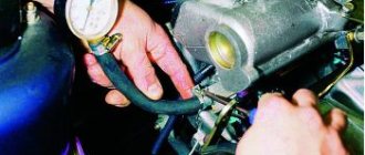
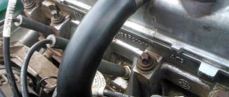
Following the manual, we checked the voltage at the knock sensor connector. Outputs 0 and 5 V on two wires. Far from normal values. It's time to print out the engine electrical circuit diagrams.
The connector should receive black-yellow and violet-gray wires. What do we have?
Although the chip is fully connected, the wires of the wrong colors are connected. To the right of the chip you can see another similar two-pin connector - for the generator. My first thought is, have they been confused?
Again we turn to the circuits - this time to the generator circuits. Everything is in order here: there is a chip with the correct gray and brown wires. Just for fun, we swapped the connectors - they snap into place! It's easy to confuse! Now it remains to understand: what happened to the wires to the knock sensor? After all, according to the scheme, they should be a different color. Maybe the diagram is wrong?
Remove the connectors on the engine control unit. We see that the wires are the correct colors - black-yellow and violet-gray. Here's a mystery - they can't change color along the way!
The solution turned out to be simple: another sensor was hidden behind the drive shaft.
This is the oil level sensor. And also with a two-pin connector. This is the same connector that should be on the knock sensor.
Thank you, Opel! You just have to figure out how to assemble three sensors with the same connectors in one place. Ignorance or inattention of “specialists” led to huge financial expenses for the car owner. I had to pay 60,000 rubles to replace serviceable parts.
Our hostess only left money for an hour and a half of diagnostics. There was no need to change anything. This is the main quality of a good diagnostician - the ability to thoroughly check everything possible, and only then recommend repairs. Order diagnostics only from professionals - it’s much cheaper this way!
Many of us have encountered such a problem as turning on the engine icon (Check engine...), the appearance of which frightens car drivers. We offer you the 5 most common reasons why the check engine light comes on on the dashboard.
For most drivers, the appearance of this warning icon on the dashboard means the need to urgently go to an auto repair shop to diagnose and eliminate the reason why the “Check Engine” warning sign appeared. But in fact, in most cases, when the “Check” indication appears, it is possible, and in some cases, perhaps, to eliminate the cause yourself without a trip to a car service center, which will save you money.
Is it worth putting rings in the Astra tidy?
Installing aluminum rings in the panel is one of the most popular types of aesthetic tuning among owners of the Opel line. It is believed that thanks to them the shield looks more solid. Thanks to the reflection of the backlight from the metal surface, the speedometer, tachometer and odometer readings appear clearer. Many Astra owners choose to add rings because they are a cheap way to give the panel a more modern look.
One of the advantages of such tuning is its simplicity. To install the rings, you often don’t even need to remove the tidy. It is enough to remove the protective glass of the instrument panel.
Subaru (Tokyo, Japan)
In the constellation Taurus there is a cluster of stars called Subaru (this is the Japanese name, in the west it is called the Pleiades). In this constellation, 6 stars are visible to the naked eye, which we see on the company’s logo, only they are located differently than in the cluster.
A little history: the Subaru auto concern is a division of Fuji Heavy Industries (FHI), which is engaged in aircraft manufacturing. The head of the company, Kenji kita, was an ardent supporter of automobile production and was very passionate about it. He held a competition to choose a name for the P-1 car (the first passenger car prototype produced by the company in 1954), but none of the proposed options interested him. Then he gave it the name that he had been nurturing in his heart for a long time - Subaru. This name, in Japanese, is consonant with the word Mitsuraboshi, which literally means six stars. Another interesting fact is that FHI was formed by the merger of exactly 6 companies.
Opel cars
- 1st generation, 2013 - today
- 1st generation, 2014 - today
- 1st generation, 2008 - today
- 1st generation, 2021 - today
- 2 generations, 2006 - today
- 6 generations, 1998 - today
- 1st generation, 2012 - today
- 1st generation, 2012 - today
- 1st generation, 2001 - 2011
- 7 generations, 2000 - today
- 3 generations, 2007 - today
- 1st generation, 2021 - today
- 1st generation, 1998 - 2003
- 1st generation, 2021 - today
- 1st generation, 2006 - 2009
- 4 generations, 2008 - today
- 2 generations, 2013 - today
- 1st generation, 2009 - today
- 1st generation, 2015 - today
- 1st generation, 2021 - today
- 4 generations, 2002 - today
- 2 generations, 2012 - today
- 1st generation, 1999 - 2003
- 3 generations, 1996 - 2009
- 1st generation, 2014 - today
- 5 generations, 1999 - today
Infiniti (Tokyo, Japan)
At first, the designers wanted to use the infinity symbol - the Mobius loop - in the logo. But then they decided to display in the emblem a symbol of a road going to infinity, a symbol hinting at an endless path to perfection in everything.
The name of the brand translates as infinity, limitlessness.
Infiniti is a subsidiary of Nissan and its history is quite interesting. It all started in the distant sixties of the 20th century. At this time, the Nissan auto company entered the US market. Americans sensed the benefits and began to buy the company’s inexpensive and reliable cars. Nissan soon established itself as a manufacturer of economy cars, and therefore it was not practical to launch higher-end cars under the same brand. This is why the Infiniti brand was created.
How to reset errors
For cars with EasyTronic and manual gearboxes, this sequence of actions is relevant.
If diagnostics have previously been carried out using this method and the fault is completely eliminated, the error will no longer appear.
For automatic transmission
In the case of automatic gearboxes, the sequence of actions looks slightly different:
In cars with automatic transmission, it is important to carry out the procedure so that the limit switches operate. Therefore, you need to press the gas pedal as deeply as possible so that a characteristic click appears. At the same time, apply moderate force to the brake.
Lightning
Subsequently, the Opel logo changed a large number of times. In 1909, it was depicted in the form of only the Opel inscription, made in gold. From 1910 to 1930, the shape resembled the human eye and was made in various color and stylistic variations.
In the 1930s, the company began producing very fast trucks, and lightning appeared on the logo for the first time. Its silhouette consisted of the words Opel Blitz.
In the 1940s, the company came under state control. All its resources are now aimed at building up the military potential of Nazi Germany. To show the country's engineering excellence and technological development, the Opel logo features an airship passing through the letter "O".
At the end of the war, the factory in Rüsselsheim was almost completely destroyed by Soviet troops. Later it returns to private ownership, resuming the production of peaceful products. Now it produces not only cars, but also bodies and components, locating factories in various countries around the world.
Since 1964, the logo has taken the form of a lightning bolt that crosses a circle horizontally. Despite some changes in style, the overall image has remained the same since then. This is how the Opel logo is known to us today.
Tidy pinout
Allows you to know which wires to connect to which contacts during assembly and disassembly of the device. And also what they are responsible for.
| Contact | Color | Wire diameter | Purpose |
| 6 | Black White | 0,5 | Rear defogger switch signal |
| 10 | Black-Purple | 0,5 | Air conditioner request |
| 11 | Yellow Red | 0,5 | Computer command LED “Car trip” |
| 12 | Green-Brown | 0,5 | Disabling the rear parking aid LED |
| 13 | Brown-White | 0,5 | Relay control of fog lamp |
| 16 | Red | 0,5 | Battery positive voltage |
| 17 | Black-Purple | 0,5 | Emergency switch blinker control |
| 18 | Brown-Blue | 0,5 | Rear window wiper switch |
| 19 | Grey-Yellow | 0,5 | LED brightness adjustment signal |
| 20 | Brown | 0,5 | Weight |
| 21 | Brown | 0,5 | Weight |
| 27 | Black | 0,5 | Ignition voltage |
| 28 | Grey-Blue | 0,5 | Front fog light switch |
| 29 | Grey-Purple | 0,5 | Instrument panel lamp brightness switch signal |
| 31 | Grey-Green | 0,5 | Rear parking assist switch off signal |
| 32 | Brown-Black | 0,35/0,5 | Rear fog light switch signal |
| 33 | Yellow | 0,5 | dipped headlights |
| 34 | Green | 0,5 | Low-speed GMLAN data |
| 35 | Green | 0,5 | Likewise |
| 36 | Brown-Yellow | 0,5 | Headlight Switch Reference Low |
| 37 | Grey-Green | 0,5 | Signal of parking lights of the headlight switch |
| 38 | Brown-White | 0,5 | Door lock/unlock signal |
| 39 | Black Brown | 0,5 | Tire Pressure Monitor Reset Switch Signal |
| 40 | Green-White | 0,5 | Emergency switch signal |
| 41 | Yellow-Black | 0,5 | Signal for switching the computer command “Trip auto” |
| 42 | Brown-White | 0,5 | Relay control of rear defogger |
Explanation of icon symbols
The symbols on the Astra G panel received their final form, as well as a link to the errors they indicate, in 1999, a year after this generation of cars was released. The table shows what they mean and which lights represent which important information.
| Icon | Designation |
| Automatic headlight axis alignment enabled | |
| System (SRS) | |
| Buckle up | |
| Brake or clutch failure | |
| Problem with engine cooling. | |
| On diesel engines it indicates the operation of heating the glow plugs | |
| Lamp for electrical control systems of engine/automatic transmission/automatic locking | |
| Low battery charge or incorrectly installed terminals | |
| Check - problem with the motor | |
| Low oil level | |
| Front fog lights | |
| High beam | |
| Rear fog lights | |
| Turn signals | |
| Lamp for switching the AT to sport mode (if equipped) | |
| Anti-skid in action (TCS)/ (ESP) | |
| (ABS) | |
| Refuel | |
| Trailer turn signal | |
| Seat occupancy indicator lamp |
The key is on
The appearance of a wrench icon on the instrument panel indicates the need for general maintenance. They dump him at the service station.
Instrument cluster
Warning lamps and indicator lights of the instrument panel
The completeness of the instrument panel with warning lamps and light indicators depends on the modification of the car. Warning lamp for automatic adjustment of the angle of the optical axes of the headlights. Warning lamp for the supplementary safety system (SRS). Warning lamp for “Don’t forget to fasten your seat belts!” Warning lamp for the brake system/hydraulic clutch drive. Warning lamp for the cooling system. Electronically Controlled Engine Routine Maintenance Engine Preheat Warning Lamp (Diesel Models) Electronic Engine Control/Automatic Transmission/Start Interlock Warning Lamp In some cases, the fault may be corrected by turning the ignition off and attempting to start the engine again. Charge Warning Lamp On models equipped with Z12XE engines, Y20DTL, Y20DTH and Y22DTR, the possibility of malfunctioning of the power unit cooling system cannot be ruled out. If necessary, seek assistance from a car service specialist. Engine failure warning light (Check Engine / MIL) Oil pressure warning light Routine maintenance Fog light activation warning light High beam headlight activation warning light Rear fog light activation warning light Turn signal indicators A noticeable increase in the frequency of flashes indicates an exit from by building any of the turn signal lamps. Indicator lamp for switching the AT to sport mode (with the appropriate vehicle configuration) Indicator lamp for traction control system (TCS) / anti-skid system (ESP) Triggering of electronic motion stabilization systems may be accompanied by a slight decrease in the power developed by the engine (the produced engine background noise). The possibility of automatic braking of the vehicle cannot be excluded. The ESP system serves to prevent the risk of loss of control of the vehicle in emergency situations and its operation should remind the driver of the need to coordinate the speed limit with the condition of the road surface. Anti-lock brake system (ABS) warning lamp The ABS self-diagnosis process may be accompanied by specific sounds. If the lamp refuses to turn off, or if it lights up while driving, this indicates that the self-diagnosis system has detected a problem in the ABS circuit. At the same time, the braking system goes into normal operation mode, which means that movement can continue unhindered. To troubleshoot problems, seek help from the specialists of the vehicle manufacturer's original service station. The built-in ABS self-diagnosis system can significantly simplify the process of finding and eliminating the causes of system failures. If the ABS and brake system warning lights are activated at the same time, you should immediately stop driving, gradually reducing the speed. vehicle out of traffic and park on a safe section of the road
Braking should be done with extreme caution, avoiding sudden pressure on the pedal. Fuel reserve indicator lamp Try to avoid running out of fuel completely! This warning especially applies to diesel models, the removal of air from the power system of which is one of the rather labor-intensive procedures.Trailer turn signal warning lampSeat occupancy registration warning lamp
Description and location of indicators and instruments on the panel
Opel control panel with component designations
The instrument panel of the Opel Vectra A or any other model may have some differences in terms of equipment - in this case it all depends on the modification of the vehicle.
- The indicator lights up if the system cannot recognize the electronic key (either it is broken, or its position is incorrect, or the battery is simply dead). It should be noted that the key should not be left in the luggage compartment or placed in front of the information screen. The icon will light up if the steering wheel is in a locked position. If the indicator lights up while driving, the car must be stopped immediately and the cause must be discovered, as an error may lead to an accident.
- This indicator appears when the ignition is activated and informs the driver that the pressure level in the lubrication system has decreased. When the engine starts, the icon should disappear. Operating a car with the indicator on can lead to damage to the power unit.
- The indicator lights up when the ignition is activated, as well as when the handbrake lever is raised, after starting the engine it should go out. Operating a car with a lit icon is not recommended.
- This indicator also appears when the ignition is turned on, but if it appears while driving, it may indicate a problem with the airbags. When this icon appears, it is better to seek help from specialists, because the airbags may not only not work at the right time when an accident occurs, but may also activate spontaneously. And this, in turn, can also lead to an accident.
- A tachometer that tells the driver how many revolutions the engine is holding while driving.
- The light appears when the ignition is turned on, but should disappear after the engine starts.
- This indicator will go out only after the driver fastens the seat belt.
- The indicator of open car doors and luggage compartment also disappears after starting the engine.
- If this icon continues to light after the engine has started, this may indicate a lack of charge in the on-board network. The problem may lie in the performance of the battery, for example, by shorting the circuit, and this, in turn, is fraught with a possible fire. The indicator may also appear as a result of wear, breakage, or weak tension on the alternator belt. If the problem is the latter, and the strap on the mechanism is intact, then perhaps the cause should be sought in the voltage regulator.
- The left turn signal lights up when the driver turns on the corresponding steering column switch. If the light bulb begins to blink more often, this may indicate that it has burned out. Sometimes the reason lies in the safety device.
- Fuel level indicator in the tank; while driving, it appears if there is approximately 80 km of fuel left. Remember that regular operation of a car with a low level of fuel in the tank can lead to damage to the fuel pump.
- The fuel level sensor itself.
- Right turn signal.
- Speedometer - thanks to this device, the driver always knows at what speed his vehicle is moving.
- The Check light on the dashboard of an Opel Astra G, H or any other model is an indicator indicating a malfunction in the engine. The icon appears when the ignition is started, but after the engine starts it disappears, this is normal. But if it begins to appear while driving, you need to diagnose the power unit.
- The ABS indicator, if it begins to appear while driving, it is better to stop using the car until the problems in the operation of the anti-lock braking system are resolved. In most cases, the reason for the appearance of the icon is simply a sensor failure, but sometimes the problem lies precisely in the performance of the system.
- Tire pressure monitoring system light. If it appears while driving, it is advisable to pump up the tires.
- The cruise control system indicator lights up when it is activated.
- Icon for monitoring the status of the adaptive lighting system. If a breakdown is detected, it is advisable to make a diagnosis or contact a specialist, since operating a car with such a problem is undesirable.
- Glow plug switch icon.
- The light for turning on the rear fog lights appears on the dashboard only when the lights are turned on.
- Distant lighting.
- This icon is only relevant for cars with an automatic or robotic transmission. It appears on the dashboard when the driver turns on the winter mode of the box.
- A similar situation - the symbol appears only when the sport mode is activated on automatic or robotic gearboxes.
- Interactive screen for “automatic machines” and “robots” - it shows the current transmission.
- Odometer screen - thanks to it, the driver knows how many kilometers his car has traveled and how many kilometers he has driven in a day.
- This is the symbol for the sensor used to detect the occupancy of the front passenger seat.
- Front fog lights.
- Power unit overheating symbol. If it appears while driving, the car should be stopped immediately and the cause of engine overheating should be found and eliminated.
- Indicator of breakdown or incorrect operation of the dynamic driving system, as well as the shock absorber control system.
- This symbol indicates that the Parktronic system, designed to ensure safer parking of the car, is not working correctly or is not functioning at all.
- The instrument panel of the Opel Vectra A is equipped with this symbol if the car is equipped with an Easytronic robotic transmission. This light indicates that the engine cannot be started.
- Symbol for turning on side lights.
- The engine fluid pressure level in the system is too low; it is necessary to stop the engine and solve the problem.
- Control indicator of power unit and transmission control systems (author of the video about tuning the control panel - channel Ulugbek Ishmatov).
Advantages of narrow specialization
There are more and more cars, and their design is more and more complex. It is impossible to efficiently repair thousands of different models. It's like trying to learn all the sciences at once - you won't know any of them perfectly. Same with cars. Each model has its own characteristics and requires special equipment, not to mention the human factor - the master, due to physiology, cannot know the structure of all machines. But thoroughly learning the design of just one model is a completely doable task.
And this is our strength - we repair only Opel cars. Since our founding, we have purchased equipment only for Opel. We trained our mechanics only on repairing this machine. For many years we dreamed about Opel at night, but it gave results - today we know everything about this car.
Therefore, if the letter F lights up on the Opel instrument panel, call us. We will determine what the problem is over the phone and either bring the car to us or send a mobile service station to fix everything on the spot. We do not inflate prices, since there are a lot of service stations and with high prices we simply will not have customers. Call to learn more about our services.
Diagnostics of Opel Astra H without a scanner
To read errors on your car, you don’t have to go to a service center or buy a scanner. There is an option to use one of the two methods below. Much depends on which gearbox is installed on the car - manual/robotic or automatic.
If a computer is not available or there is no special adapter for connection, you can perform the diagnostics yourself. To do this, just start the self-diagnosis mode.
For manual and robotic gearboxes
The sequence of actions if you have a car with a manual or robotic gearbox is as follows:
- The driver simultaneously presses the gas and brake pedals. The ignition must be turned off at this moment.
- While continuing to press the pedals, you need to insert the key into the ignition and turn it. There is no need to start the engine.
- On the instrument panel (where the mileage is displayed) the inscription “ECN” (error code number) and detected errors in the form of codes will be displayed. If there are several errors, they will be displayed one by one. To understand what exactly the problem is, you need to decipher the code.
For automatic transmission
If your car is equipped with an automatic transmission, you can read the error code like this:
- Insert the key into the lock, turn it, wait until the ignition turns on. There is no need to start the engine.
- Depress the brake pedal. At this time, without removing your foot from the pedal, move the gearbox to position “D”.
- Turn off the ignition and take your foot off the pedal.
- Depress the gas and brake pedals at the same time. At this time, also turn on the ignition.
- If everything is done correctly, you will see “ECN” (error code number) and error codes on the dashboard.
Note! When performing self-diagnosis on a car with an automatic transmission, you must press the gas pedal to the floor. The brake is an exception; it can be pressed with average force.
The beginning of the way
Looking at the photo of the Opel logo, everyone will probably think about cars. This association is firmly attached to the company, because it has been producing them for more than a hundred years. Today it is a large international firm with a presence in Europe, America, South Africa and Asia with annual revenues in excess of $18 billion. Over the course of a century, it produced tens of millions of cars, but it did not start with transport.
The company originated in 1862 as a small manufactory producing sewing machines. Its founder was Adam Opel along with his sons, who took an active part in the family business.
Adam named his first car model “Sofia” in honor of his wife, and the company’s first logo displayed his own initials. The company’s emblem depicted a curly letter “O” in red, inside which was the same curly gold letter “A”.
Symbols for vehicle system faults and safety warnings.
If you see the indicated symbols on the dashboard, then contact the dealer or car service directly as soon as possible.
Attention! Symbols (icons) are listed in order of importance, from severe to less severe warnings
| The icon lights up along with a warning message on the instrument panel. In European cars, a yellow symbol(color) indicates a malfunction of the stability control system. |
| Airbag error. |
| Indicator of inactive side airbags. |
| Warning about unfastened seat belts for the driver and front passenger. |
| Warning about unfastened seat belts for rear passengers. |
| Car alarm indication/Immobilizer icon. |
| Gearbox error. Automatic transmission malfunction. |
| Warning about overheating of the automatic transmission or drive system. |
| Transmission overheating or clutch problem. |
| The oil temperature in the gearbox is too high. |
| Power steering malfunction. |
| Parking brake (handbrake). |
| Low brake fluid level. |
| Anti-lock braking system. |
| Brake pad wear symbol. |
| Problems with the electronic control of the brake system. |
| Malfunction of the electric parking brake (handbrake). |
| Warning that you must press the brake pedal before starting the engine or before shifting the gearbox. |
| Tire pressure monitoring system. If it appears, check the pressure. |
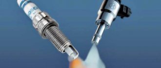
| Check Engine - Engine check. Read more here... |
| Check the engine electrical equipment. |
| Reduced engine power. |
| Engine malfunction. |
| Lambda probe. Oxygen sensor fault indicator. |
| The gas tank is not closed. Air in the fuel system. |
| A symbol indicating the presence of an information message in the system. |
| The need to read the vehicle's operating manual. |
| Overheating or malfunction of the catalyst. |
| Low coolant level. |
| Engine cooling problems / Low coolant level. |
| Problem with electronic throttle control system. |
| Air filter contamination indicator. |
Decoding the symbols of the tidy indicators
The icons and indicators are described in the numerical order shown in the figure above.
| Number in order | Meaning |
| 2 | The oil pressure in the engine has dropped critically. It is necessary to replenish the level or check the functionality of the pump. |
| 3 | The traction control system operates normally. |
| 4 | The airbags are faulty or disabled. |
| 5 | The requirement to press the gas pedal. |
| 6 | The vehicle's stability control system is disabled or malfunctioning. |
| 7 | The battery is worn out or discharged. |
| 8 | Central locking indicator |
| 9 | Requirement to fasten seat belts. |
| 10 | A malfunction of the brake system can also indicate wear on the brake pads. |
| 12 | Warning lamp of the fuel level indicator in the gas tank; when the lamp lights up, the car can travel another 30-40 kilometers. |
| 15 | The ABS system is disabled or damaged. |
| 16 | Catalyst malfunction. |
| 17 | Indicator for automatically turning on the wipers. |
| 18 | The adaptive headlights system is switched off. |
| 19 | The lamp lights up when problems with the brakes are detected; the pads may be worn out. |
| 20 | The Shift indicator tells you when it is best for the driver to shift to a higher gear. |
| 21 | The light is used only on diesel engines. The icon indicates that the glow plugs are on. |
| 22 | The aft fog lights are activated. |
| 23 | Automatic low beam switching works normally. |
| 24 | The stabilization system is turned off. |
| 25/38 | The turn signals are also activated when the emergency lights are turned on. |
| 26 | Front fog lights included |
| 27 | Problems have been detected in the operation of automatic transmission components. |
| 29 | Tire pressure sensor indicator. |
| 31 | There is not enough fluid in the washer reservoir. |
| 32 | One or more doors are open. |
| 33 | The immobilizer is activated, the vehicle cannot be moved. |
| 34 | The high beam headlights are on. |
| 35 | The handbrake lever is raised. |
| 36 | Lamp for turning on the backlight. |
| 37 | The on-board system for automatically switching low and high beam headlights is included. |
| 39 | Power steering malfunction. |
| 40 | Cruise control is on. |
| 41 | Requirement to check the engine. |
What does a car with a key mean?
The indicator on the dashboard indicates that the standard anti-theft system is turned on. If the immobilizer is activated, the vehicle cannot be driven. To disable it, you will need to disarm the car using the key fob.
Bicycles
In the 80s of the 19th century, Adam's sons became interested in a relatively new invention at that time - bicycles. They constantly participate in popular bicycle races and are working on the company's next product.
In 1886, the company produced penny farthings - models with a high front wheel, and then moved on to the production of “safe” (Safety bicycle) models, which are still common today.
The Opel logo is completely changed. In a gray oval field in the shape of the letter "O" a cyclist is depicted, above whom the goddess of victory hovers with a laurel crown in her hand. At the top, in an oval edging, is the inscription Victoria Blitz (“lightning victory”), and at the bottom is the name of the company owner.
Later, the emblem turns into a figured Opel inscription on a red background, framed by a gold ornament. At the top is the date - 1899 - at the bottom is the inscription Fahrräder, which means “cyclist”. This is the logo that was present on most of the company’s products.
Information displays on the dashboard for technical messages and warnings.
In recent years, in all modern cars, manufacturers have begun to install information displays in the dashboard, which are designed primarily to provide the driver with more detailed information about the car, as well as about the many operating systems in the car. Typically, this information screen is installed in the car in the center of the dashboard.
In the car market nowadays, there are a huge number of cars that are equipped with a similar screen; this screen is capable of displaying various information about errors, various warnings, etc. signals.
How to perform self-diagnosis
Modern cars are able to inform the car owner about possible breakdowns. To make such a diagnosis, you should first of all always pay attention to the light icons that light up on the dashboard.
You can also use a special diagnostic scanner. It should be connected to a laptop or smartphone and read all the necessary error codes in the operation of vehicle systems. Moreover, such scanners not only provide the necessary digital designation, but also decipher it.
However, not everyone has such a device. Fortunately, you can do without it. You just need to display the necessary information on the LCD display of the vehicle control panel. If we are talking about a vehicle equipped with a manual transmission or a gearbox, which is popularly called a robot, then you only need to complete a couple of steps. While driving a car, the car owner must lightly press the brake and gas pedals at the same time. Don't try too hard, just a little touch is enough. In this position you only need to wait a few seconds. After this, continuing to press both pedals, you need to start the engine and wait a few seconds. A six-digit code should appear on the monitor. It will contain information about the error, if any.
If we are talking about an automatic transmission, then the manipulations will be somewhat different. To activate the code messages, you must turn on the ignition and press only the brake pedal. The force applied is also average. After this, the gearshift knob is moved to position “D” and the car owner turns off the ignition and also releases the pedal. At the next stage, it is enough to simultaneously press the gas and brake with both feet and turn on the engine. After a couple of seconds, a digital code will appear on the dashboard.