Not all experimental aircraft reach large-scale production. Sometimes it is not possible to organize mass production of even machines of outstanding quality. This happened with the multi-role carrier-based fighter Yak-141. It could become the first production supersonic fighter with vertical takeoff and landing. The aircraft has already demonstrated high, at that time unattainable for analogues, flight characteristics.
But in the end, the aviation of the Russian fleet turned its back on it, and none of the foreign customers were interested in it. And the vague prospects of the Yak-141 gradually turned into non-existent.
A brief history of the creation of vertical take-off and landing aircraft
Due to the development of the technical side of turbojet engines in the 50s of the last century, it became possible to create an aircraft with vertical take-off. A big impetus for the development of VTOL aircraft was the active development of jet aircraft in the advanced countries of the world. It should be noted that these devices had a high speed during landing and takeoff; accordingly, it was necessary to create a long runway, and accordingly they must have a hard surface. This requires additional cash injections. During hostilities, there were very few airfields that could accommodate such aircraft, so the creation of an aircraft with vertical takeoff and landing could solve a lot of problems.
During these years, a huge number of variants and prototypes were produced, which were built in one or two copies. In most cases, they crashed during testing, after which the projects were closed.
In 1961, the NATO Commission put forward requirements for a fighter with vertical landing and take-off, which gave additional impetus to the development of this area of aircraft construction. After this, they planned to create a competition to select the most promising designs. But the competition never took place, since it became clear that each advanced country had its own versions of such an aircraft.
Under the influence of technical and political problems, the NATO commission changed the concept and put forward new requirements for the apparatus. After this, the design of multi-purpose machines began. Ultimately, only two options were selected. The first was the aircraft of the French designers "Mirage" III V", 3 aircraft were created and the designers of the Federal Republic of Germany VJ-101C produced 2 copies. After the tests, 4 devices were lost. Because of this, it was decided to develop a fundamentally new vehicle, the XFV-12A.
Development of VTOL aircraft in the USSR and Russia
The first aircraft of this class in the USSR was the Yak-36, which the Yakovlev Design Bureau began to develop in 1960. For this purpose, a training stand was made. The first flight was carried out in March 1966, in this test a vertical take-off was carried out with the transition to horizontal flight, after which the machine landed vertically. After this, the Yak-38 and the more famous Yak-141 were created. In the 90s, another project was started with the designation Yak-201.
Description of the Yak 141 aircraft
the Yak 141 based on the normal aerodynamic design of a monoplane with a high wing. The design of the machine consists of aluminum and lithium alloys - these are lightweight and durable materials that are not subject to corrosion. In parts of the structure where the engines were installed, heat-resistant alloys and hardened steel were used. Approximately 30% of the airframe and empennage are made of composite materials.
The shape of the wing is a trapezoid with a sweep of 300, and there are swells at the points where it connects with the fuselage. For deployment on ships, the wing is made folding. The flaps were placed in the root part, and in the folding part there were ailerons connected to the mechanism for controlling the jet rudders. The rectangular fuselage is made in the form of a semi-monocoque with four flaps that serve for safe hovering and landing.
In case of failure of the rotary nozzle, a brake parachute is provided, located in a special compartment above the main engine. Two fins with rudders and a rotary stabilizer mounted on the beams of the tail consoles represent the tail of the aircraft.
One R79V-300 engine, used for acceleration and ascent, and two RD-41, used only for ascent, form the basis of the aircraft’s power plant.
Yak 141 bottom view
Air flow to the main engine was provided by adjustable rectangular air intakes located on both sides of the fuselage. In hovering mode, when conventional rudders are ineffective, the pitch angle changes due to the difference in the thrust of the main power plant and the thrust of the two lifting engines. The course of the vehicle is determined by jet rudders in the end consoles of the rear fuselage, and the roll is changed due to jet rudders located in the wing tips.
Behind the pilot's compartment there are two lifting engines, closed by three doors - one at the top and two at the bottom of the fuselage, which open automatically when the power plant starts.
The canopy of the pilot's cabin consists of two sections, the windshield is flat, made of armor, the part that is dropped during ejection opens up and to the right. The pilots' instrument panel is equipped with analog indicators; later, some of them were replaced with a line-of-sight indicator and a head-mounted indicator on the windshield.
The usual chassis design consists of three lever-type supports that can withstand the load when dropped from a height of five meters.
The Zhuk airborne radar with a slotted antenna array is capable of detecting an air enemy using electronic countermeasures at a distance of up to 80 km, tracking 10 targets simultaneously and hitting four of them at once. An infrared track and search system sensor and a laser distance meter help accurately track targets.
Equipment for ejecting dipole reflectors and heat traps is located in the pre-keel space of the vehicle. Electronic countermeasures equipment is located at the tips of the fins and wing consoles.
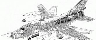
Yak 141
Layout diagram
Depending on the position of the fuselage
- Vertical.
With screws.
- Reactive.
Using thrust directly from a propulsion jet engine.
- Coleoptera (ringed wings).
- With screws.
Rotary wing and propellers.
- Rotary type motor.
Links
- d/f
rotorcraft Autogyro • Helicopter • Helicopter backpack • Rotorcraft • Tiltrotor • Multicopter • Synchroptera Aerostatic Balloon (charlier · hot air balloon · rosier · stratospheric balloon) • Airship Aerodynamic Airplane • Seaplane • Flying submarine • Gondoloplane • Ekranoplane (Ekranolet) Rocket-dynamic Rocketplane • Jetpack (Martin Jetpack · Griffin) • Cruise missile Other Ornithopter • Muscleflight • Cyclocopter
Vertical takeoff and landing
At the same time, a similar aircraft was being developed in England. In 1954, the Harrier vertical take-off aircraft was built. It was equipped with two engines with a thrust of 1840 kg. The weight of the aircraft was 3400 kg. The plane turned out to be extremely unreliable and crashed. Watch vertical takeoff and landing .
The next step in the development of such devices was the American aircraft, built in 1964. The construction coincided with the development of the lunar program.
Despite the fact that breakthroughs in the field of aircraft manufacturing do not delight us every day, there are a lot of new developments in the field of civil aviation. A typical example of this is the development of a modern vertical take-off passenger airliner.
The main features of aircraft with vertical take-off are, first of all, that a large space is not required for take-off and landing of the aircraft - it should only slightly exceed the dimensions of the aircraft, and from here there is a very interesting conclusion that with the development of airliners with a vertical take-off system, Air travel between different regions will become possible, even those without any airfields. In addition, it is not at all necessary to make such airliners spacious, because 40-50 seats are quite enough, which will make air travel as cost-effective and comfortable as possible.
Vertical take-off video - watch above
However, a vertical take-off aircraft will most likely not be famous for its speed, since even in military aircraft it does not exceed 1100 kilometers per hour, and given that a passenger aircraft with a vertical take-off will carry a relatively large number of people, then most likely its cruising speed will be the speed will be about 700 kilometers per hour. However, on the other hand, the reliability of air travel will increase significantly, since in the event of any unforeseen situation, a vertical take-off aircraft can easily land on a small, flat area.
Today, there are a number of concepts for future passenger airliners with a vertical take-off system. Until recently, they seemed incredible, but modern developments in the field of aircraft manufacturing indicate the opposite, and it is quite possible that in the next ten years, the first modern aircraft with vertical take-off will begin to transport their passengers.
SUGGESTED OPTIONS
An increase in absolute and relative regularity will make it possible to move the lifting propulsion engines forward by 10–15% closer to the center of mass. Some widening of the fuselage will make it possible to change the linear-sequential layout to diagonal or transverse, which shifts the vector of the lifting thrust of the lifting engines closer to the center of mass to maintain balance.
An even greater possibility of moving the vertical thrust of the PMD will be given by improving the engine gas generator by increasing the pressure of the fan and compressor stages, and using a final high-pressure centrifugal compression cascade. This will “pull” synchronous PD movements towards the center of mass for balance.
Variations in the layout of lifting motors can be as follows.
First of all, we are talking about abandoning the upper intake of essentially atmospheric air and replacing it with supercharging of lifting engines, extraction from an oversized PMD fan and supply through an elastic air duct directly to the PD. At the same time, the normally folded air duct-sleeve straightens out and lifts the lever-hinged upper panel of the fuselage (so as not to waste the precious volume of the aircraft). A sleeve made of material resistant to pressure, temperature and cyclic folding is often reinforced with counter-diagonal Kevlar-Dacron winding (cord). The sleeve is a consumable type, replaced after the expiration of the cyclic and temporary warranty.
The PMD is taken from the fan by a circular volute, through the bypass windows, closed by a tape with a rotating device, for example a hydraulic cylinder, by a leash. The volute contains a funnel - a PD feeder, onto which an air duct with a metal-plastic tip is attached - a sector rotary lock (like a fire hose) duplicated with eccentric tension locks (like old suitcases). All locks are equipped with a wire lock, equipped with an information tag and a personal seal of the quality control inspector. The air duct at the junction with the PD contains a similar set of locks, but with a significantly, visually different, larger diameter of attachment to the asymmetrical and crooked funnel of the PD air intake.
Of course, the increased air flow through the engine due to supercharging proportionally increases thrust, potentially up to 20–30% with additional fuel consumption. A lifting engine is a highly efficient machine with a specific thrust parameter that is unattainable for cruising (an indicator of the ratio of engine weight to developed thrust). For the PD of the late 1960s it ranged from 1:16 to 1:18, for the late 1980s it reached 1:30, and for the 1990s - 2000s it was predicted at 1:40 or more. For comparison, the propulsion engines of 4th generation fighters barely reached 1:8+ in afterburner and this was a technological breakthrough, otherwise called a leap in quality, achieved by advanced research under the ATEGG (advanced gas turbine engine gas generator) and LWGG (light weight gas generator) programs.
So, the lifting RD-41 has a thrust of 4.2 tons, with supercharging it’s already 5.5–6 tons. However, not all so simple. Let's assume that the initial pressure increase in the compressor is 5 units. With a boost of 1.5–2 units, 7.5–10 compression ratios will be provided. You can counteract the increased load by injecting a water-alcohol mixture of summer and winter consistency, respectively. If this measure is not enough, it will be necessary to reduce the boost pressure, or follow the analogy of racing and sports piston engines with turbocharging, reducing the compression ratio in the engine.
The combustion chamber is also a critical area. However, the design calculation must take into account surge surges, so we hope for a margin of stability. But the turbine complex is a truly problematic area. The increased pressure, even at a constant temperature and a slight decrease in temperature by 50–70 degrees Celsius, can exceed the flow rate and other capabilities of the turbine by excessive spin-up or separation.
Russian ingenuity suggests four options for overcoming the problem.
Option one, barbaric: the linear-frontal method involves surge bypass (dumping) of part of the compressed air from the middle and final part of the compressor into the flow transported by an oval air duct beyond the turbine area. If this measure is not enough, you can relieve the turbine-rotor by thinning the guide blades-stator. If this measure is not enough - reduce the compressor by 1-2 high pressure stages or inject part of the cooled fuel multi-point into the area of the high pressure compressor and possibly medium pressure to absorb the temperature of the compressed air - removing part of the thermodynamic load of the compressor.
Option two is to control thermogas dynamics by injecting a water-alcohol solution into the air intake and turbine cooling system.
The third option - speculative due to the lack of drawings of the RD-41 engine and its parameters - refers to an emergency emergency during a rough vertical landing with an excess of the descent speed. Perhaps the post-turbine part, together with the RD-41 thrust vector control ball nozzle, will allow additional combustion of kerosene in the presence of oxidizer injection to obtain additional thrust for braking. In the R-79 engine, this can be solved more easily, and balancing can be done by briefly turning on the liquid-propellant rocket engine in the bow according to the rocket cycle. The implementation of the idea of boosting the PD will make it possible to control the total lift force in flight. For example, to escape from an attack, evade, accelerate a turn, that is, survive in combat conditions. The same goes for close combat, including with a ground enemy using contrasting terrain like a helicopter.
Finally, the last, fourth option. It determines the feasibility of creating a special supercharged engine. PD supercharging entails a reduction in size and weight. Thus, the length (height) is reduced by 40-50%, and the weight by 30-40%, which makes it possible to supplement the PD with an afterburner. Hence the expected increase in specific thrust of 1:40-1:45 already at the first stage, in the subsequent 1:50-1:60 and more. It looks like the game is worth the candle.
Disadvantages and advantages of VTOL aircraft
Without exception, all devices of this type were created for military needs. Of course, the advantages of such machines for the military are obvious, since the aircraft can be operated in small areas. Airplanes have the ability to hover in the air and at the same time make turns and fly sideways. When compared with helicopters, it is clear that the greatest advantage of airplanes is their speed, which can reach supersonic levels.
However, VTOL aircraft also have significant disadvantages. First of all, it is difficult to control; this requires high-class pilots. Special skill is required from the pilot during the transition of modes.
It is the complexity of control that poses many challenges for the pilot. When switching from hovering mode to horizontal flight, it is possible to slide to the side, which creates additional problems when holding the aircraft. This mode requires a lot of power, which can lead to engine failure. The disadvantages include the small carrying capacity of the VTOL aircraft, while it uses a huge amount of fuel. During operation, specially prepared sites are required that are not destroyed under the influence of gas exhaust from engines.
"Vertical" at supersonic
Work on the Yak-141 aircraft began in 1973, when the Yak-38 had not yet made its first landing on the deck. Testing was planned for 1982, but development was delayed, largely due to difficulties in developing a rotating nozzle.
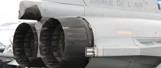
Initially, it was planned to use a flat two-dimensional nozzle, but due to lack of experience, it was decided to switch to a traditional, axisymmetric one. This nozzle is divided into three segments, which, rotating in different directions, provide thrust deflection.
This allows you to use afterburner in both horizontal and vertical modes. The work was successfully completed, but the delay in designing the aircraft played a cruel joke on him.
At first, it was decided to postpone the testing of the aircraft until 1985, and then the restructuring that began slowed down work on the project even more. As a result, the Yak-141 took off only in 1987, and in 1992, the plant of the estate of A. S. Yakovlev, trying to save the project deprived of government support, presented the aircraft at the Farnborough Air Show. There was hope for foreign orders, but it was only possible to agree on cooperation with Lockheed.