Hunting repeating rifle designed by A.S. Shesterikov chambered for 9×53 with a semi-jacketed bullet and with or without
. It was mass-produced from 1965 to 1976 by the Izhevsk Machine-Building Plant. Currently produced in the form of modifications Los-4 and Los-7 chambered for 7.62×51.
This product was the first in the Elk carab
A trigger mechanism that is simple in design and reliable in operation has been developed, with the ability to adjust both the force and the nature of the trigger.
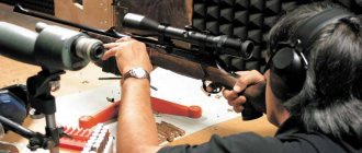
The magazine is non-detachable for 5 rounds, the weight of the carbine is 3.1 kg. A 4x optical sight was installed on the carbine. The disadvantage of this carbine was the short distance of up to 100 m
for effective shooting, after which the bullet energy quickly dropped.
With carbine Elk
You can hunt in any climatic conditions and at ambient temperatures from minus 50 to plus 50 C. The kit with the carbine includes accessories for disassembly, cleaning, lubrication, a carrying belt and a case for storage and transportation.
[edit] General characteristics
The barrel bore is locked by turning the sliding bolt by the handle onto two lugs. The bolt has a striker cocking indicator, which creates additional convenience, especially when shooting at dusk, and increases the safety of handling the carbine.
- The impact mechanism is striker-type, with a separate mainspring. The firing pin is cocked when the bolt is unlocked.
- The trigger mechanism is assembled in a separate housing and, using adjusting screws, can be adjusted to different forces and the nature of the release is smooth or with a warning
.
- Removal of the cartridge case (cartridge) from the receiver is carried out by an ejector, which removes the cartridge case from the chamber, and by a protrusion of the sear, reflecting it in a certain direction.
- The safety lever, which locks the trigger and prevents rotation of the bolt, is located on the right side of the receiver.
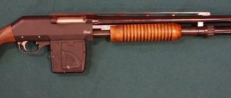
- The magazine is integral, box-shaped, double-row, hidden in the fore-end.
- An open sector-type sight allows shooting at a distance of up to 500 m.
- The stock is single, with a semi-pistol neck and a rubber butt pad.
- The carabiner is equipped with a carrying belt, a case, accessories and documentation. The optical sight was supplied only upon request.
Owner reviews
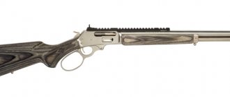
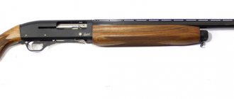
Many owners note the excellent combination of the attractive external design of the Los 7 1 carbine and its good technical characteristics, which provides both firing range and excellent lethality. The use of natural wood in the manufacture of the stock and polymer materials with high resistance to external influences allows you to maintain the appearance of the carbine even with frequent use in the field.
Owners also speak well of the carbine’s ability to hit a distant target, which is ensured by the high speed of the bullet when fired.
[edit] Technical characteristics of the Elk carbine
| Caliber, mm | 9 |
| Weight without optical sight, kg | 3,1 |
| Carbine length, mm | 1060 |
| Barrel length, mm | 550 |
| Initial bullet speed, m/sec | 630 |
| Magazine capacity, cartridges | 5 |
| Trigger force, kgf | 0,5 — 1,5 |
| Nature of the descent | adjustable |
| Sighting line length, mm | 470 |
| Sighting range, m | 500 |
| Firing accuracy Psr. at 100 m , mm | 110 |
Options and packaging
The basic kit for the Los 7 1 carbine includes an optical sight, which can be replaced with a more voluminous one, a front sight, a forend and a cleaning rod for cleaning the weapon. Also, when sold, the carbine is accompanied by a quality certificate and an individual passport.
The carbine is packaged in a polymer material: this makes it possible to maintain its attractive appearance during transportation and avoid damage to the relatively soft wood that forms the butt.
Los-7-1 (308 Win) Legion
[edit] History of creation
The history of the creation of the carbine is as follows. Since 1961, the Izhevsk plant has produced hunting carbines based on the S. I. Mosin three-line rifle in three versions: KO-8.2, KO-8.2M and KO-9 chambered for cartridges with a sleeve length of 66 mm 8.2×66; 8.2x66M; 9×66
.
However, the energy of the bullet, despite all the modernization of the cartridge, turned out to be insufficient. As a result, Izhmash specialists had to start developing a new hunting carbine for fairly powerful rifle-type ammunition. In 1964, A.S. Shesterikov developed the KO-8.1-1 or Los-8.2 models. At first, as can be seen from the figure, the caliber remained the same. But since 1965, this carbine began to be made for a more powerful 9x53 cartridge, proposed by M.N. Blum back in the 50s, renaming the carbine KO-9-1 (“Los-9”) or simply the Los
. It was produced at Izhmash during 1965-1977, remaining consistently popular. To this day it remains the most common type of weapon chambered for the 9x53 cartridge.
The main technical characteristics are common to all three modifications: carbine length 1050 (1060) mm, barrel length 540 mm (550 mm), aiming line length 460 mm (470 mm), barrel bore has six right-hand rifling with a pitch of 320 mm, direction of rifling right. Original and exceptionally simple in the Elk
became a shutter - it was disassembled into 4 parts almost in one movement.
For the Mosin rifle, this unit was much more complex and consisted of a stem with a handle, a combat cylinder, a firing pin, a trigger, and a connecting bar with a stand
. The bolt lugs and the corresponding receiver lugs were located near the barrel hem, providing a short locking arm and thereby high structural strength. A great advantage was also the preliminary release of the spent cartridge before ejecting it, which increased the reliability of the weapon.
The modified 9x53A cartridge was significantly more effective than the 8.2x66M, surpassing it in initial speed by almost one and a half times, and twice as much in energy. True, certain complaints from hunters were caused by the fact that the 15-gram bullet flew along a too steep trajectory, which is why the target firing range did not exceed 300 m.
Therefore, designer M.M. Blum (son of M.N. Blum) developed an improved 9x53 ammunition - with a 13-gram expansive bullet and an initial speed increased from 680 to 750 m/s. Its flight trajectory became flatter and its target firing range increased. Unfortunately, for a number of reasons, this successful cartridge was released in only a few experimental batches. But in 1975, employees of the Central Research Institute of Precision Engineering proposed a new hunting cartridge 7.62x51 - a kind of analogue of the .308 Winchester ammunition. Its bullet, which had an initial velocity of 830 m/s, was expansive, weighed 9.7 g and retained energy at a distance much better than a heavy 9 mm bullet with a worse configuration. The 7.62x51 case did not have a protruding flange, but only a groove to which the ejector clung, so that the supply of cartridges from the magazine was almost perfect. Taking into account the capabilities of this ammunition, Izhmash designers A.S. Shesterikov and M.F. Luchinkin modernized the carbine in 1975. The new modification, which made it possible to conduct targeted shooting at a target at a distance of up to 300 m, was called Los-4. In 1990, the Los-4 carbine was discontinued and replaced by the Los-7 (KO-7) hunting carbine chambered for 7.62×51, characterized in that the trigger mechanism with the safety lock is located in the bolt clutch, making the design of the carbine much more simplified, the number of parts decreased compared to the Los-4 carbine.
Design
- The modified front sight in combination with the optics (optical sight) of the Los 7-1 carbine allows you to hit the target with the greatest degree of accuracy, and the ability to replace many parts of the carbine with more powerful or modern ones makes it possible to improve it.
- The simplicity of the design allows the carbine to be disassembled, which may be necessary for its routine repair or cleaning. The barrel is made of high-quality steel, its length is the most optimal for the model. The varnished stock, made of wood (birch or walnut), is pleasant to use and retains its attractiveness due to high-quality processing.
- The magazine that comes with the carbine as standard includes 5 rounds of ammunition, which are arranged in a checkerboard pattern. If necessary, the basic magazine can be easily replaced with a more spacious one.
[edit] Device
Hunting carbine model Elk
consists of the following parts and mechanisms: barrel with receiver, bolt, impact and trigger mechanisms, magazine, feed mechanism, sights and stock.
- The barrel is rigidly connected to the box with threads. The 550 mm long barrel with six grooves has a thickening in the breech, inside of which there is a chamber. The thickening has a thread cut for connection to the receiver. The bore and chamber are chrome plated.
- On the breech and muzzle of the barrel, an aiming block and the base of the front sight are pressed and secured with pins, on which an open sighting device is attached on top, and a cleaning rod on the bottom.
- An aiming bar is mounted on top of the sighting block, spring-loaded with a leaf spring. A scale with numbers from 1 to 5 is marked on it through certain sections, which corresponds to distances of 100, 200, 300, 400 and 500 m. A clamp moves along the bar, which rests with its lower part on the sector made on the back of the sighting block and determines the position sighting bar. The clamp is secured with a latch.
- The rear part of the aiming bar is a mane, in the middle of which there is a slot on top for aiming - the rear sight. On the top of the front sight base there is a transverse groove in the shape of a dovetail
. The front sight is pressed into this groove. A notch is applied to the inclined surface of the base of the front sight to diffuse light.
- The receiver in the front part has a threaded hole for attaching the barrel and a through channel with longitudinal grooves for movement of the bolt. On top of the receiver there is a base for attaching an optical sight bracket and a window for loading and extracting the cartridge case.
- At the rear of the receiver there is a hole for the base of the bolt handle. At the bottom of the receiver there is a window for the magazine, grooves for the trigger mechanism and a socket for the fuse; the receiver lugs are located at the beginning of the through channel in front of the magazine window. In the magazine window, inside the receiver, there are protrusions for holding cartridges in the magazine. Below in front of the window for the store there is a stop that fits into the recess of the stock. There are holes for connecting screws in this stop and in the rear of the receiver.
- The bolt is longitudinally sliding, with rotation when locking, which is carried out by two lugs located in the front part of the bolt. The bolt contains a firing pin with a mainspring, an ejector with a spring and a clutch. Inside the bolt there is a through channel in which the firing pin, mainspring and clutch guide tube are placed. In the front part, the channel narrows to a small hole for the passage of the firing pin.
- The shutter cup is designed to accommodate the bottom of the cartridge case; a groove for the reflector and a groove in which the ejector and spring are assembled on the axis go into it. The lugs are located on the front of the bolt. At the rear of it there is a reloading handle, a figured groove with a spiral and cracked protrusions for attaching the clutch.
- The drummer has a channel inside for the mainspring and a figured protrusion with a cocking spiral and a combat cock. The front part of the firing pin forms the firing pin. There are two thickenings on the cylindrical surface of the firing pin, which act as guides when the firing pin moves inside the bolt.
- The coupling consists of a cup and a guide tube. The hammer cocking indicator is placed inside this tube. The bolt with the firing pin and the mainspring are connected by a coupling. The mainspring is preloaded when the bolt is reloaded.
- The firing pin is cocked when the bolt is opened at the moment the reloading handle is rotated upward by 90°, while the firing pin, with its cocked protrusion, jumps into the hole at the end of the figured cutout. When the bolt is subsequently pulled back, the protrusion of the sear enters its groove, and then, resting against the end of the groove, stops the bolt. When the bolt moves towards the barrel, a cartridge from the magazine is sent into the chamber. When the bolt is turned, the firing pin stops on the sear. When turning, the bolt lugs slide along the annular recess of the receiver. During the final turn, the bolt moves forward slightly, and the cartridge is completely sent into the chamber, and the lugs move beyond the lugs of the receiver, locking occurs.
When the bolt is opened, the base of the handle slides along the spiral surface of the receiver groove, causing the bolt to move slightly rearward. At the same time, the sleeve also shifts, since the ejector hook prevents the sleeve from leaving the bolt cup; a preliminary shift of the sleeve occurs
. When the bolt is pulled back, the cartridge case is removed from the chamber and transferred to the rear wall of the magazine. At this moment, the end of the sear enters the groove of the bolt, the sleeve hits the bottom of it and flies out of the receiver.
- The trigger mechanism is located in a separate trigger box and consists of a sear, trigger, regulator, screws and spring.
- The sear is an L-shaped part, the front end of which tapers and serves to reflect the liner. The sear is assembled in the trigger box on a tubular axis. It is spring-loaded with a torsion spring, one end of which rests against the front end of the sear, the other against the hole on the front wall of the trigger box.
- The trigger in the upper part has an inclined protrusion, the front surface of which rests against the fuse. Somewhat lower there is a protrusion for interacting with the sear, and at the back there is a recess in which the trigger spring is placed.
- The trigger regulator is an L-shaped part, the rear end of which is located under the protrusion of the trigger, and the upper end rests against the lower end of the sear. In the middle part of the regulator there is a hole for an axle, which at one end is attached to the side wall of the trigger box. The regulator allows you to configure the trigger mechanism to operate with a warning
or for
a smooth
release.
Adjustment is made with front and rear screws screwed into the trigger box. The front screw rests on the upper end of the regulator and determines its position depending on the type of setting for a smooth
descent with low force,
a smooth
descent with great force, or a
warning
. In the first case, the protrusion of the trigger does not touch the regulator.
When descending with a warning
the protrusion rests on the end of the regulator after some rotation of the trigger. The rear screw rests against the trigger spring and provides adjustment of the force on the trigger.
- The trigger box body is a stamped-welded structure, open on one side. The axes of the trigger, regulator and sear spring are riveted into the holes in the side wall of the case at one end. At the bottom there are two holes for adjusting screws and a window for the trigger. The trigger box body is attached to the receiver using two pins. The front pin, in addition, is the axis of the sear and the leaf spring, which fixes the fuse in a certain position; the end of the rear pin limits the rotation of the fuse. The trigger mechanism is closed on the side with an easily removable cover, which has clips at the front and back that fit into the corresponding sockets of the trigger box.
To adjust the trigger mechanism to a certain force and the nature of the trigger, it is necessary to separate, first of all, the barrel with the box from the stock, then insert the assembled bolt and cock the firing pin. If desired, you can remove the trigger cover, but then the barrel with the box should be placed on the right side.
To obtain a smooth change in the trigger with low effort, screw in the front adjusting screw so that the front protrusion of the trigger does not touch the adjuster when the sear is completely released.
To obtain a smooth release with great effort, the front screw should be unscrewed so that the regulator, under the action of its spring, rests against the front protrusion of the trigger. In this case, two springs work. The force on the trigger is adjusted by the lower adjustment screw, but the stroke of the hook is not adjustable.
To set the release with warning
You should use the front adjusting screw to set the gap between the regulator and the front shoulder of the trigger to ensure the required amount of
warning
. In this case, initially the trigger will rotate freely, compressing only its spring. Then, when there is minimal engagement of the sear with the hook, the protrusion of the trigger rests on the regulator, and the trigger spring begins to compress. After meeting the regulator, the force increases sharply as the force spring begins to compress. With further very small movement of the trigger, the hook disengages from the sear, followed by a shot.
After adjustment, close the lid and finally assemble the carabiner.
The safety device against accidental shots is located in the transverse groove of the receiver and is secured by the trigger housing. For convenience, the fuse box at the top has a thickening with a notch. On the cylindrical base of the flag there are two cutouts into which a leaf spring fits, fixing the fuse in two positions. The middle part of the fuse is a blade that has a protrusion at one end for interacting with the bolt, and at the other a groove in which the upper protrusion of the trigger moves.
To put the mechanisms on fuse, you need to turn the fuse box to a vertical position. In this case, the safety blade fits into the groove of the bolt with one end, excluding accidental opening of the bolt, and the other locks the trigger. For convenience, the letters O (fire) and P (protection) are placed on the receiver. The open letter shows which position the fuse is in. The magazine is a stamped-welded box, which is attached to the receiver using the front protrusion and is pressed in from behind by the trigger box. In the front wall of the magazine there is a cutout for the feed mechanism lever. Two profile corrugations are extruded on its side walls, which increase the rigidity of the magazine and ensure the direction of movement of the cartridges.
- The connecting strip with the help of two screws ensures the assembly of the barrel with the box in the stock. It is a stamped-welded trough-shaped part in the form of a rectangle with an extension in the middle part. Inserts with threaded holes for screws are welded to the front and back of the bar and two windows are made: the front one for the passage of the cartridge feeder and the rear one for the trigger. The feed mechanism and the safety bracket with the magazine cover are fixed in the front part of the bar.
- The lever-type feed mechanism consists of a feeder, a feed lever, a feed spring and axles. The feeder is a stepped plate with a hole for the axle. The feed lever is a U-shaped stamped-welded part with a widening at the bottom and narrow at the top, in which the feeder with a spring is fixed. The lower end of the lever on the axle is secured in a safety bar.
The front part of the connecting bar is the magazine cover, and the rear curved part is a bracket that protects the trigger from accidental pressing. In front of the window for the passage of the trigger there is a window with bends in which the latch is mounted.
The stock is a single one made of birch, or less often walnut, with a semi-pistol neck and a butt with a cheekpiece that is not adjustable in length. Reinforced with a special “Nagel bolt”. Front and rear sling swivels are attached to the fore-end and butt. In front of the fore-end there is a trough-shaped recess on top for the barrel and a longitudinal groove for the ramrod. In the rear part of the forend there is a through window for the magazine, a window for the trigger mechanism and two holes for connecting screws. A transverse steel liner is fixed behind the front hole, on which the receiver stop is based. On the right side of the forend there are two recesses for the reloading handle and for the safety catch. There is a rubber shock absorber at the end of the butt.
Design of the carbine Elk
has much in common with that of the Bars carbine.
[edit] Loading and unloading
When loading, open the bolt of the carbine by turning its charging handle up and pull it back all the way. Equip the magazine with cartridges, pressing them to the rear wall of the magazine and placing them in two rows. The receiver flaps keep them from jumping out of the magazine. After loading the magazine, the bolt must be pushed forward by the handle. When the bolt moves towards the barrel, a cartridge from the magazine is sent into the chamber. To fire, you must remove the safety and pull the trigger.
To reload the carbine, you need to open the bolt, pull it back as far as it will go, push it forward again and close it. When the bolt is pulled back, the cartridge case is removed from the chamber and ejected from the receiver.
To unload the carbine, you need to press the magazine cover latch, which is located in front of the trigger in the eyes of the safety bracket, and turn the cover down and forward. The feed mechanism comes out of the magazine body, and the cartridges in the magazine freely fall out of it. If there is a cartridge in the chamber, it must be removed. Then put the mechanisms on safety.
[edit] Disassembly and assembly
The rifle must be unloaded to disassemble. Then, if there is an optical sight, unscrew the bracket clamp nuts a few turns and separate the bracket with the sight from the receiver. After this, open the bolt, pull it back all the way, pull the trigger and remove it from the receiver. Next, by opening the magazine cover and unscrewing the connecting screws, separate the barrel with the receiver and remove the bar with the feed mechanism from the stock. To separate the trigger box, knock out the axis and pin of the trigger mechanism. To remove the fuse from the receiver, place the fuse box in a horizontal position, remove the fuse and remove the lock.
To disassemble the bolt, it is necessary to move the bolt clutch forward, overcoming the force of the mainspring, and turn it clockwise until it stops. Remove the clutch from the bolt, remove the mainspring and firing pin.
Disassemble the trigger mechanism: remove the cover of the trigger box, remove the spring; knock out the tubular axle; press the trigger all the way and remove it, making sure that the hook spring does not fly out; Unscrew the adjusting screw, releasing the release spring and regulator. Assembly is carried out in reverse order. When assembling, you should pay attention not to ensure that the firing pin inserted into the bolt is fixed in the figured groove.