Signs of a malfunctioning knock sensor. Check and replace at home. (Part 1)
Good day, friends.
I was often asked questions about this device, so in today’s article I would like to answer you the most frequently asked questions about this. After all, many car owners believe that a malfunction of the knock sensor does not interfere with the operation of the engine in any way, and in some ways they are right, but as always there is one BUT - over time, this malfunction will lead to the failure of other systems and mechanisms of this circuit. And this is much more waste on repairs than checking and, if necessary, replacing the knock sensor. But not everyone knows that in order to check and replace it is not necessary to go to a service center and ask for help from specialists, who most often have a level of knowledge in this area equal to yours and, in fact, will do a not so difficult job for which they will demand a tidy sum from you (I am now I don’t want to make anyone look stupid, it just happened to me personally in life). So, I just want to convey to people that all these procedures with a sensor are done very simply and do not require huge investments and waste of time. The main thing in this matter: 1) Perseverance; 2) Attentiveness; 3) Accuracy; 4) Well, hands from the place that God gave us)
Well, let's start with the basics.
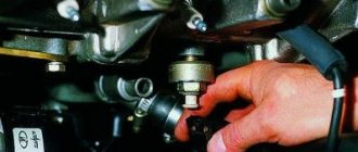
What is a knock sensor? But here everything is simple - this is a part (part) of the control system that is responsible for controlling the level of detonation. Where can I find it? Everything is easy here too - we look on the engine cylinder block. Friends, just don’t get confused and don’t look for it on carburetor engines
. This sensor is installed on injection-type gasoline engines (where there is an electronic ignition system) and specifically on the engine body. The size of this part (if anyone hasn’t seen it) is literally proportional to the size of a matchbox.
It should also be noted that thanks to this device it becomes possible to save fuel
and the ability of the motor
to develop maximum power. The knock sensor regulates the vehicle's starting system and its operation.
In modern cars, as you know, you can see the operation of the sensor on the instrument panel and if there is a malfunction, the indicator will let you know about it.
(CHECK)
So, let’s now look at the operating principle of this device.
It consists of a piezoelectric mechanism (there is a plate inside that has a piezoelectric effect). So, when that same detonation occurs, voltage appears at the output and input. The result is engine vibration. A so-called potential difference is created, in which the voltage level at one end exceeds the level at the other. The sensor, in turn, “is engaged” in adjusting this process.
If for some reason the sensor fails, the “
Check ” indicator lights up on the instrument panel.
Conclusion - immediate repair or replacement of the sensor itself is necessary.
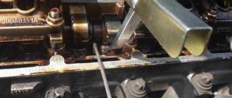
Connecting high-voltage wires ZMZ 405, ZMZ 406
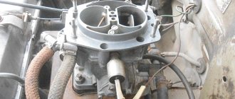
ZMZ carburetor and Euro-2 engines are equipped with a DIS (Double Ignition System) ignition system.
The DIS system uses ignition coils with two high-voltage wires. Each coil operates a corresponding pair of cylinders.
The first coil works with 1 and 4 cylinders, the second coil works with 2 and 3 cylinders.
How to connect the ignition coils?
The ignition coil of cylinders 1 and 4 is located closer to the intake manifold, the coil of cylinders 2 and 3 is closer to the exhaust manifold.
Low-voltage coil wires must be connected to the coil in pairs. The pair of wires for coil 1-4 is slightly shorter than the pair of wires for coil 2-3.
Within the pair, it does not matter which contact is connected to which wire - the coils are non-polar. Also, within the pair, it does not matter which high-voltage wire goes to which cylinder.
Let's look at an example (see photo)
Coil 1 control (cylinders 1 and 4) – green and yellow wires. This pair connects strictly to the coil of cylinders 1 and 4!
Low voltage circuit - polarity is not important - can be connected:
Option 1: The top coil contact is yellow, the bottom contact is green.
Option 2: The top coil contact is green, the bottom contact is yellow.
High voltage outputs – polarity is not important – can be connected:
Option 1: Top outlet for cylinder 1, bottom outlet for cylinder 4.
Option 2: Top outlet for cylinder 4, bottom outlet for cylinder 1.
Coil 2 control (cylinders 2 and 3) – blue and yellow wires. This pair is connected strictly to the coil of cylinders 2 and 3! Further - similar to pair 1-4 - the polarity within the pair is not important.
The determining factor when connecting pairs of low-voltage and high-voltage wires to the corresponding ignition coil is the correctness of their routing. The wires should not be too tight, bent too much, and should not rub against fixed parts of the engine or other wires.
Another article about high-voltage wires ZMZ 405, 406 - read so as not to repeat this mistake.
Did you like the article? Follow our channel for new ideas of useful car tips. Subscribe to us on Yandex. Zene. Subscribe.
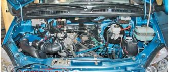
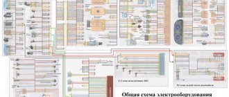
Very often, Gazelle owners, when replacing power units from carburetor versions to injection ones, are faced with the need to replace the electrical wiring in the car, since there are serious differences in the electrical circuit.
However, a complete replacement is not always justified, since the repair does not affect other electrical devices except the ignition and fuel injection systems.
Reduced pressure in the power system
1. Remove fuse No. 9 (fuel pump fuse) from the right fuse box.
2. Start the engine and let it run until the fuel is completely exhausted from the fuel line.
After this, the engine will stall.
3. Reinstall the fuse.
4. Replace damaged chain guides.
5. After this, you can disconnect the fuel lines.
Replacing the mass air flow sensor
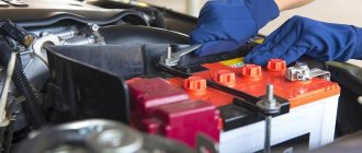
1. Disconnect the wire from the negative terminal of the battery.
2. Disconnect block 1 from mass air flow sensor 3.
Loosen the clamps, disconnect the air supply hoses 2 and remove the sensor 3. 3. Install the new sensor in the reverse order.
Checking the mass air flow sensor
1. Remove the mass air flow sensor.
2. Connect a voltmeter to contacts “2” and “3” of the sensor connector.
Apply a direct current of 12 V to contacts “1” and “5” (n) to contact 5, and <—> to 1).
In this case, the voltmeter should show a voltage of 1.3-1.4 V.
Then briefly close contacts “4” and “5” with each other. The voltmeter should show a voltage of about 8 V and the platinum thread should become red hot. If at least one of these conditions is not met, replace the sensor.
Adjusting the carbon monoxide (CO) content in exhaust gases
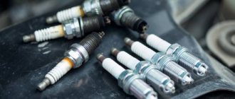
1. The adjustment is made on a warm engine (coolant temperature 80–90 °C) with a working ignition system and nominal gaps between the spark plug electrodes.
3. If the CO content is higher than the specified limits, adjust the CO content with screw 1 on the mass air flow sensor.
When turning the screw clockwise, the CO content increases, and counterclockwise, it decreases.
In this case, the content of CH will also be adjusted.
If it is not possible to adjust the content of CO and CH within the specified limits, you need to check the serviceability of the elements of the integrated microprocessor engine control system.
Replacing the accelerator cable
Disconnect the wire from the “Negative” terminal of the battery.
2. Unscrew nut 1 and remove accelerator cable 2 from sector 3 of the air throttle valve drive.
3. Move the oil seal 1 from the cable tip, completely unscrew the nut 2 from the cable tip, pull out the cable shell tip 3 from the bracket and lift the cable up from the bracket through the slot.
Remove the tip 3 from the cable by removing it from the outer 4 and inner sheaths of the cable.
4. Remove the outer 1 and inner sheaths of the cable from the tip 2 on the front panel
5. Remove cotter pin 1 from pin and remove pin 2.
Move the oil seal 4 and remove the bracket 3.
6. Pull the cable through the end on the front panel into the passenger compartment.
7. Install the new accelerator cable in the reverse order and adjust it.
Adjusting the accelerator cable
1. Loosen the tightening of nut 1 securing the cable 2 on sector 3.
2. Loosen the tightening of nut 2 of adjusting bolt 1 between the upper 4 and lower 3 levers of the accelerator pedal.
3. From the sector 3 side of the throttle valve, pull out cable 1 until it stops.
In this case, the upper lever 5 of the accelerator pedal should rest against the buffer 4 on the bracket. Tighten nut 2 securing the cable to the sector.
In this case, the throttle valve must be completely closed.
4. Pull the upper lever of the 4th pedal towards you until it stops.
Holding the upper pedal lever 4 in this position, turn the lower pedal lever 3 until it stops on the mat and tighten the nut 2 of the adjusting bolt 1
5. When adjusted correctly, when the pedal is fully released, the throttle valve should be completely closed and the upper pedal arm should rest against the buffer on the bracket.
When the pedal is fully depressed, the throttle valve should be fully open and the lower pedal arm should rest against the floor mat.
6. You can adjust the position of the cable by moving the tip 1 of the shell in the bracket, loosening the tightening of nut 2. After adjusting, tighten nut 2.
Removing the throttle assembly
1. Disconnect the wire from the negative terminal of the battery.
2. Disconnect the accelerator cable from the throttle sector
3. Disconnect block 1 with wires from the throttle position sensor.
Loosen the clamps and disconnect the hoses of the idle air regulator 2 and crankcase ventilation 3.
4. Loosen the clamps and disconnect hoses 1 of the throttle heating, having previously marked them.
Immediately plug the hoses with plugs to prevent loss of coolant.
Unscrew the four fastening bolts 2 and remove the throttle 3 with the gasket.
5. If it is necessary to remove the throttle position sensor 2, unscrew the two screws 1 securing it.
Replacing the idle air control 1. Disconnect the wire from the negative terminal of the battery.
2. Loosen the clamps and disconnect hoses 1 and 2 from regulator 5. Disconnect the block with wires from connector 4 of the regulator.
Unscrew the two mounting bolts 3 and remove the regulator. Remove regulator 5 from clamp 6.
3. Install the new idle air control in the reverse order.
Checking the idle air control
1. Remove the idle air control.
2. Apply a direct current of 12 V to the middle contact of the regulator connector and alternately to the side contacts
In this case, the damper should rotate, opening or closing the opening of the inlet channel. If this does not happen, then the regulator is faulty and needs to be replaced.
Replacing injectors
1. Reduce the pressure in the power system if the engine has just been stopped.
2. Disconnect the wire from the negative terminal of the battery.
4. Loosen the clamps and disconnect the fuel supply hose 1 from the fuel line 3 of the engine. Disconnect fuel drain hose 4 from the pressure reducing valve.
Disconnect the connectors with wires from connectors 5 of the four injectors.
5. Remove the injector from the engine fuel line. The injector is fixed in the hole in the fuel line only with the help of an O-ring.
Unscrew the two fastening bolts 2 and carefully remove the fuel line 3 of the engine, removing the injectors from the holes in the intake pipe.
The injectors are fixed in the holes of the intake pipe only with the help of O-rings.
6. Install the new injector in reverse order.
Checking the injectors
1. To check the tightness of the injector valve, you need to lower the sprayer of 1 injector into a container with gasoline or kerosene and apply compressed air at a pressure of 0.3 MPa (0.03 kgf/cm).
If air bubbles come out of the injector nozzle, the injector valve is leaking and the injector must be replaced.
2. To check the serviceability of the injector electromagnet winding, apply a direct current of 12 V to the injector connector. In this case, a characteristic click should be clearly heard, which indicates the opening of the injector valve.
If this does not happen, then the injector is faulty and must be replaced. This check can be carried out without removing the injector from the vehicle.
3. The resistance of the injector solenoid winding can be checked with an ohmmeter by connecting it to the contacts of the injector connector.
The resistance should be in the range of 15.5-16 ohms. If the resistance value does not fall within the specified limits, replace the injector.
Replacing the pressure relief valve
2. Disconnect the wire from the negative terminal of the battery.
3. Remove the engine fuel line.
4. Disconnect fuel drain hose 1 and vacuum hose 4 from pressure reducing valve 3.
Unscrew the two fastening bolts 2 and remove the pressure reducing valve 3 from the engine fuel line.
5. Install the new valve in reverse order.
Replacing and checking the timing sensor
1. Disconnect the wire from the negative terminal of the battery.
2. Disconnect the connector for wire 3 of the sensor, located behind the engine intake pipe.
Unscrew bolt 2 and remove sensor 1.
Check the resistance of the sensor coil with an ohmmeter; it should be in the range of 850–900 Ohms.
If the resistance value does not fall within the specified limits, replace the sensor.
Install the sensor in reverse order.
For normal operation of the sensor, the gap “a” between sensor 1 and synchronization disk 4 must be within 1.0–1.5 mm.
Symptoms of a knock sensor failure.
Hello. Today I wanted to talk about the knock sensor and the symptoms of its failure. Using the example of VAZ family cars.
The knock sensor is an important element of modern engine management systems. In carburetor systems, the ignition angle was changed by adjusting (turning) the distributor. In injection systems, the adjustment is controlled electronically.
On engines of the VAZ family, the knock sensor (DS) is installed on the cylinder block between the 2nd and 3rd cylinders.
The operation of the sensor is based on the piezoelectric effect. From mechanical impact, the sensor begins to generate voltage. The sensor is located in the place of greatest heating, from where the spread of detonation combustion begins. The sensor is configured to perceive noise with a frequency of 25-75 Hz.
As written above, from the influence of mechanical impulses, the knock sensor begins to generate voltage, which is supplied to the electronic engine control unit (ECU).
If the voltage exceeds the critical value, the electronic unit, after processing the signal, adjusts the ignition angle, making it late. The system then optimizes fuel injection. This allows you to achieve efficiency and maintain the intended engine power.
If the knock sensor fails, the engine malfunction lamp comes on. The following errors may occur: "Open knock sensor", "Low noise level". If there is increased noise during engine operation, the following error message may appear: “High noise level.” If the sensor fails, you can continue driving, the car will not stop. But the following symptoms and consequences should be noted:
- Loss of engine power;
- Deterioration of throttle response;
- Increased fuel consumption.
We check the condition of the connector and wires leading to the sensor. If everything is fine with them, we change the sensor.
It should be noted that a quality knock sensor is not easy to find. There were even dummies: there was no piezoelectric element inside the sensor. The contacts were just sticking out in the plastic. I buy knock sensors from the Autocom manufacturer.
Not an advertisement. You'll just save time. But even here there are already fakes.
Source
Can the device fail?
Like any other part, this device may stop sending a signal to the ECU.
This may indicate a temporary failure or complete failure of the device. This can happen due to:
- the presence of large corrosive formations;
- wiring violations (this indicates an open circuit);
- serious malfunctions that occurred due to the device being broken;
- incorrect replacement of the device itself.
But are there any signs of trouble? Undoubtedly. A breakdown may be indicated by uncharacteristic engine behavior, which manifests itself in:
- a clear drop in engine power;
- a sharp increase in speed at low speeds;
- significant deterioration in car acceleration performance;
- increased consumption of fuel fluid.
All these symptoms indicate that something is wrong with the device. But before you think about buying a new device, you should diagnose the old one. To do this, you need to know how to check the knock sensor, as well as where it is located. Let's focus on the last one for now.
What is a knock sensor and why is it needed?
This part is found in cars that use gasoline as fuel. It is intended for injection types of engines. The sensor is located on the engine cylinder block. This is an important part of the control system, the main purpose of which is to control the level of detonation.
In answering the question of what the knock sensor is responsible for , it should be noted that thanks to it the following vehicle capabilities are realized:
- Fuel economy.
- The ability of the engine to develop maximum power.
The sensor monitors the vehicle's starting system and regulates its proper operation.
What are the main components of a knock sensor?
The main details of this mechanism are:
- Vibrating plate.
- Piezo type electrical element.
- Signal wire.
- Braid.
Where is the knock sensor located?
Depending on the make of the car, the location of the sensor may vary, but it is always located on the engine body. The part itself is very small, about the size of a matchbox.
Part installation features
An important feature of installing the sensor is the presence of an electronic ignition system in the car. If it is not there, then there is no sensor. Older models do not have a knock sensor. It is also not installed on carburetor engine systems.
Replacing the sensor on a VAZ, video:
Kinds
For the VAZ 2110, the use of two types of knock sensors is provided.
- Broadband. They regularly monitor the noise spectrum and report them to the engine control system. The corresponding signal is processed, the engine adjusts its operation.
- Resonant. They perform similar functions to broadband ones, however they only produce signals when the detonation changes.
Small differences between devices do not in any way affect their reliability, service life or efficiency. Therefore, failure of such a regulator is an extremely rare occurrence. But sometimes it happens. Most likely, the cause of the malfunction is the presence of an open circuit . First of all, it is checked. Most often, after the gap is repaired, the sensor returns to normal operation.
This is interesting: Exhaust gas temperature sensor - how is it related to odors in the cabin?
Sensor operation
There is a "Check" icon on the car's dashboard. In English this translates as check or control. If it is not active, then the knock sensor is working and working as expected.
If it is active, a comprehensive diagnosis should be carried out, since the cause is not always the knock sensor. You can do your own diagnostics using an ODBII scanner.
A special feature of this auto scanner is the diagnostics of not only the engine, but also other components of the car (gearbox, abs, transmission, etc.). The scanner is quite easy to use and has Russian-language software, which will help with identifying the malfunction. The following errors will indicate a problem with the knock sensor: P0325, P0326, P0327, P0328.
The next step would be to erase the errors using Scan Tool Pro and check whether the “Check” lights up again, in which case inspect the wiring and contacts on the sensor in detail, eliminating the possibility of breakage or oxidation.
Then you should begin checking the sensor itself using a multimeter in the manner described in the next chapter.
The operating principle of the knock sensor is based on a piezoelectric mechanism. Inside the sensor there is a plate with a piezo effect. When detonation occurs, voltage is created at the input and output, and the engine vibrates. Otherwise, this is called the creation of a potential difference. If the voltage level at one end is too high, the sensor corrects this process.
If for any reason the sensor breaks down, the “Check” icon will light up on the dashboard. This will mean only one thing: urgent repair or replacement of the element is required.
If the electrical circuit of the sensor is not broken, but a breakdown exists, the “Check” icon will not light up. Therefore, it is worth listening to your car sometimes.
Sources of DD failure
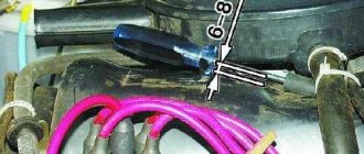
One of the main reasons is an open circuit, for this they check the terminals, then the wires ring, and when the engine operates more than 3000 rpm, self-diagnosis is activated.
If the electrical circuit is OK, you need to look for the problem in the controller itself. To dismantle the VAZ 2110 knock sensor (its location is problematic, between the cylinders) of the old model (resonant, single-contact), you need a socket wrench No. 13. For the new model of the sensor (broadband, two-contact), a key of 22 is required.
Symptoms of sensor malfunction
You can determine whether the sensor is broken without a dashboard. But this will require experience and a special approach to your car. You need to know him very well. We list the signs by which you can understand that the device is broken, from here it will be immediately clear what the knock sensor affects:
If you determine the breakdown yourself, then it’s not far to independently diagnose the sensor, as well as replace it yourself. In principle, this is not difficult, but it requires some understanding of the process.
Replacing the knock sensor
If it requires replacement, then it is necessary to purchase a new device and install it as soon as possible. All car enthusiasts are primarily interested in the price of a new device. It is low and depends on the make of the car and on the country in which the part was manufactured.
You can carry out the replacement yourself when the engine has cooled down by disconnecting the negative terminal of the battery. It is necessary to achieve the most convenient access to the sensor so that it can be removed. The fact is that it also depends on the car model.
Thus, the knock sensor is a simple device, yet very useful for an electronic control system. It is not difficult to determine its malfunction; you can check it yourself, even in rural areas.
It will also be inexpensive to replace the sensor. It doesn’t matter whether this is done by a specialist or independently.
Source