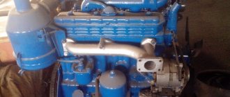
Longitudinal section of the VAZ-21126 Priora engine:
1 — oil pump of the engine lubrication system;
2 — generator drive pulley; 3 — connecting rod; 4 - piston pin; 5 — Priora timing belt; 6 — timing cover; 7 - camshaft drive pulley; 8 - intake manifold; 9 - spark plug well; 10 — oil filler cap; 11 - cooling system thermostat; 12 - flywheel; 13 - oil nozzle for cooling the piston bottom; 14 — pump oil receiver; 15-crankshaft The VAZ-2170 Lada Priora is equipped with a VAZ-21126 power unit (Figure 5.1, 5.2), made on the basis of the VAZ-2112 engine. Increasing engine displacement mod. 21126 up to 1.6 l compared to the working volume of mod. 2112 was obtained by increasing the piston stroke length at a constant cylinder diameter.
Cross section of a VAZ-21126 engine:
1 – drain plug; 2 – oil sump; 3 – oil filter; 4 – water pump; 5 – catalytic collector; 6 – exhaust valve; 7 – valve spring; 8 – exhaust camshaft; 9 – intake manifold; 10 – cylinder head cover; 11 – intake camshaft; 12 – hydraulic valve pusher; 13 – camshaft bearing housing; 14 – fuel rail; 15 – nozzle; 16 – valve guide; 17 – inlet valve; 18 – cylinder head gasket; 19 – compression rings; 20 – oil scraper ring; 21 – piston pin; 22 – connecting rod; 23 – cylinder block; 24 – connecting rod cover; 25 – oil receiver
Cylinder block VAZ-21126 Priora
The cylinder block is made of special high-strength cast iron, which makes the engine structure more rigid. The channels for the coolant, forming the cooling jacket, are made along the entire height of the block, this significantly improves the cooling of the pistons and reduces the deformation of the block due to uneven heating of the engine. The cooling jacket is open at the top towards the block head. At the bottom of the cylinder block there are five supports for the main bearings (liners) of the crankshaft, the covers (yokes) of which are secured with bolts. The supports contain thin-walled steel-aluminum liners that act as crankshaft bearings. The intermediate support has grooves in which thrust half-rings are placed, stabilizing the crankshaft from axial beats. Compared to the engine cylinder block mod. 2112 cylinder block mod. 21126 Priora is overestimated by 2.3 mm, the height from the center of the radical bearing beds to the upper plane of the block is 197.1 mm.
Pinout of the lighting control unit on Priora
This switching and control combined module has several functions and is used to turn on/off parking lights, headlights, select the desired light switching mode, turn on/off fog lights, adjust the brightness of the backlight combination, control the headlight range control, on/off and control light inside the cabin and instrument lighting. The module is connected to the vehicle’s on-board network via chip No. 1118-3724500.
The standard terminal pinout on a VAZ 2170 is as follows:
| G, 56b | To the gear motor for adjusting headlights |
| 58b | Output to backlight sources |
| 31 | Weight |
| Xz | +12 volts (from terminal 15 of the ignition switch) |
| 56 | To the relay for switching high and low headlights |
| 1,3 | From rear and front fog lights |
| 2,4 | To the rear and front fog lamp relays |
| 58 | To the size lamps |
| 30 | +12 V from terminal No. 30 of the ignition switch |
Crankshaft VAZ-21126 Priora
The crankshaft is made of special high-strength cast iron.
The main and connecting rod journals of the crankshaft are machined and ground. To supply oil to the connecting rod bearings, oil channels are drilled in the crankshaft and closed with plugs. To reduce vibration, there are eight counterweights located on the crankshaft. Engine crankshaft radius mod. 21126 is 2.3 mm larger than the engine mod. 2112, because of this the piston stroke increased from 71 to 75.6 mm. To distinguish the shafts, one of the counterweights of the crankshaft of the VAZ-21126 Priora engine is marked “11183”. At the front end of the crankshaft there is an oil pump, a timing belt timing belt pulley and a generator drive pulley, which is integral with the torsional runout damper. At the rear end of the crankshaft there is a flywheel made of cast iron. The flywheel has a steel toothed rim for the starter drive. The connecting rods are steel, forged, with covers on the lower heads. The connecting rod caps are made by tearing them off from a solid connecting rod. This ensures a higher accuracy of alignment of the cover on the connecting rod. Thin-walled liners are inserted into the lower head of the connecting rod, and a steel-bronze bushing is pressed into the upper head.
The pistons are cast from aluminum alloy. Each of them has three rings: 2 upper compression rings and a lower oil scraper ring. The bottom of the pistons is flat, with four recesses for the valves, and on the pistons of the engine mod. 21126 recesses are enlarged compared to the recesses of the 2112 engine. The pistons are cooled by oil; for this purpose, special nozzles are placed in the main bearing supports. They are made in the form of a highway containing spring-loaded balls. While the engine is running, the balls unlock the holes in the lines and a stream of oil hits the piston from below. In the engine mod. 21126 Priora uses a set of “piston-piston rings-piston pin-connecting rod” of reduced weight (piston weight is reduced from 350 to 235 g, piston pin - from 113 to 65 g, connecting rod - from 707 to 485 g, the whole set - by 32% ). The oil sump is steel, stamped, fixed with bolts to the cylinder block from below.
Self-repair of the Priora comfort unit, is this possible?
If you have never encountered soldering, diagnostics of printed circuit boards of varying complexity and configurations, or do not have the necessary diagnostic or soldering equipment, then it is better to address the repair question to qualified specialists. If you have the above skills and understand the causes of malfunctions, independent repairs are carried out quite often. This is due to the fact that various microcircuits or chips constantly fail. For example, having established that the reason for the turn signal failure is a failed control driver, it is always possible to purchase a new part and simply re-solder it to replace the faulty one.
Malfunctions and their possible causes
The cost of a new, original unit is quite high, so do not rush to buy a new product, figure out the causes of the malfunctions. Of course, there are always cases when the board cannot be repaired and it is more advisable to simply install a new product to replace the faulty one. Do not forget that the causes of malfunctions can be frayed or broken wires that are connected to energy consumers.
According to statistical data collected on technical support forums, car owners quite often complain about malfunctions in the operation of power windows, turn signals, and parking lights.
If we talk about the components of the printed circuit board itself, the most common breakdowns are associated with: - a break in the W-Line communication line; — burnout of control drivers; — burnout of controllers responsible for correct operation; - the output of their transponder; — significant oxidation of contacts.
"Important! Before carrying out any electrical work, disconnect the power supply by disconnecting the negative terminal of the battery."
Block head VAZ-21126 Priora
The cylinder head, placed on top of the cylinder block, is cast from aluminum alloy.
At the bottom of the head there are channels through which liquid passes, cooling the combustion chambers. There are 2 camshafts located on top of the block head: one for the intake valves, the other for the exhaust valves. Engine cylinder head mod. 21126 has differences from the mod head. 2112 with an increased area of flanges for the supply pipeline and spark plug wells made integral with the block head. The camshafts are placed in supports made in the upper part of the cylinder head, and in one common bearing housing, bolted to the cylinder head. The camshafts are cast from cast iron. The camshaft pulleys of the 21126 Priora engine differ from the pulleys of the 2112 engine by having valve timing adjustment risks shifted by 2°. To reduce wear, the working planes of the cams and the planes under the oil seal are heat-treated - bleached. The camshaft cams operate the valves through tappets. The 21126 engine is equipped with hydraulic valve pushers, which automatically select the clearances in the valve drive. This engine does not need to adjust the valve clearances during operation. The engine has four valves per cylinder: 2 intake and 2 exhaust. The guide bushings and valve seats are pressed into the cylinder head. The guide bushings are, in addition, equipped with locking rings that secure them from falling out. Oil scraper caps are placed on the guide bushings, reducing the penetration of oil into the cylinders. There is one spring on each valve. The camshafts are driven by a rubber toothed belt from the crankshaft.
The cylinder head cover is made of aluminum. A gasket is installed between the cover and the cylinder head. The cylinder head cover of the 21126 engine differs from the 2112 cover in the absence of a place for fixing the ignition module and the presence of holes for mounting personal ignition coils next to each spark plug well.
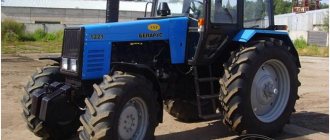
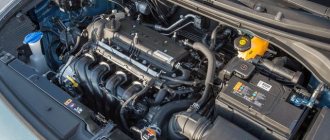
Lada Priora car engine - design description
The engine of the Lada Priora (VAZ-21126) is a gasoline, four-stroke, four-cylinder, in-line, sixteen-valve, with two camshafts. The operating order of the cylinders is: 1–3–4–2, counting from the generator drive pulley. The power supply system is phased distributed fuel injection (Euro-3 toxicity standards). The engine, gearbox and clutch form the power unit - a single unit mounted in the engine compartment on four elastic rubber-metal supports. The right and front supports of the power unit are attached to brackets located on the front wall of the cylinder block, the rear support is attached to a bracket mounted on the rear wall of the cylinder head, and the left one is attached to a bracket mounted on the gearbox housing. The right and left supports of the power unit are similar in design. The front and rear supports of the power unit are identical to each other.
Power unit (front view along the vehicle) : 1 — bracket for mounting the generator and the front support of the power unit; 2 - generator; 3 — generator drive belt; 4 — bracket for the upper mounting of the generator; 5 — bracket for the right support of the power unit; 6 - phase sensor; 7 — front upper timing cover; 8 — rear timing drive cover; 9 — inlet pipeline; 10 — ignition coil; 11 — throttle assembly; 12 — oil filler cap; 13 — cylinder head cover; 14 — low oil pressure indicator sensor; 15 — camshaft bearing housing; 16 — cylinder head; 17 — thermostat housing; 18 — thermostat cover; 19 — supply pipe of the coolant pump; 20 — oil level indicator in the gearbox; 21 — bracket for the left support of the power unit; 22 — gearbox; 23 — starter; 24 — coolant drain plug; 25 — crankcase ventilation hose; 26 — knock sensor; 27 — oil pan; 28 — oil level indicator; 29 - cylinder block
On the right side of the engine are located: timing gear and coolant pump drive (toothed belt), generator drive (V-ribbed belt), oil pump, crankshaft position sensor. On the left are: thermostat, coolant temperature sensor, coolant temperature indicator sensor, low oil pressure warning sensor, starter (on the clutch housing).
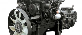
Engine (rear view along the vehicle) : 1 - diagnostic oxygen concentration sensor; 2 - flywheel; 3 — catalytic collector; 4 — cylinder block; 5 — control oxygen concentration sensor; 6 — supply pipe of the coolant pump; 7 — thermostat cover; 8 — thermostat housing; 9 — idle speed regulator; 10 — low oil pressure indicator sensor; 11 — throttle assembly; 12 — throttle position sensor; 13 — oil filler cap; 14 — inlet pipeline; 15 - eye; 16 — cylinder head cover; 17 — front upper timing cover; 18 — rear timing drive cover; 19 — camshaft bearing housing; 20 — bracket for the rear support of the power unit; 21 — cylinder head; 22 — front lower timing cover; 23 — generator drive belt; 24 — oil filter; 25 — oil pump cover; 26 — crankshaft position sensor; 27 — generator drive pulley; 28 — oil pan; 29 — oil drain plug.
Front: intake manifold, fuel rail with injectors, knock sensor, oil level indicator, generator (bottom right), timing sensor (top right). Rear: catalytic converter, oil filter, coolant pump supply pipe.
Engine (view from the left as the car moves) : 1 - flywheel; 2 — upper cover of the clutch housing; 3 — cylinder block; 4 - generator; 5 — coolant temperature indicator sensor; 6 — ECM coolant temperature sensor; 7 - nozzle; 8 — fuel rail; 9 — insufficient oil pressure sensor; 10 — crankcase ventilation hose; 11 — inlet pipeline; 12 — cylinder head cover; 13 — oil filler cap; 14 — throttle assembly; 15 — camshaft bearing housing; 16 — cylinder head; 17 — thermostat housing; 18 — thermostat cover; 19 — control oxygen concentration sensor; 20 — supply pipe of the coolant pump; 21 — catalytic collector; 22 - diagnostic oxygen concentration sensor
On top (under the plastic cover) are the intake manifold, throttle body, coils and spark plugs. The air filter housing with mass air flow sensor is located in the engine compartment to the left of the engine.
Engine (view from the right as the car moves) : 1 — oil drain plug; 2 — oil pan; 3 — oil pump cover; 4 — crankshaft position sensor; 5 — catalytic collector; 6 — oil filter; 7 — generator drive pulley; 8 — supply pipe of the coolant pump; 9 — bracket for the rear support of the power unit; 10 — idle speed regulator; 11 — inlet pipeline; 12 — throttle position sensor; 13 — throttle assembly; 14 — oil filler cap; 15 — front upper timing cover; 16 — bracket for the right support of the power unit; 17 — bracket for the upper mounting of the generator; 18 — cylinder block; 19 — front lower timing cover; 20 - generator; 21 — timing belt; 22 — bracket for mounting the generator and the front support of the power unit. Marking of the cylinder class on the bottom plane of the cylinder block.
The cylinder block is cast from cast iron, the cylinders are bored directly into the block. The nominal diameter of the cylinder is 82.00 mm with a tolerance of +0.05 mm. The calculated minimum clearance between the piston and cylinder (for new parts) should be 0.025–0.045 mm. It is defined as the difference in size between the minimum cylinder diameter and the maximum piston diameter and is ensured by installing a piston of the same class as the cylinder into the cylinder. Depending on the dimensions (diameters) obtained during machining, cylinders and pistons are divided into three classes. The class of each cylinder in accordance with its diameter is marked in Latin letters on the bottom plane of the cylinder block: A - 82.00–82.01; B - 82.01–82.02; C - 82.02–82.03 (mm).
The holes in the cylinder block for the cylinder head mounting screws have an M10×1.25 mm thread (in contrast to the holes with an M12×1.25 mm thread for the cylinder blocks of eight-valve VAZ-2111 and VAZ-21114 engines). At the bottom of the cylinder block there are five crankshaft main bearing supports with removable caps, which are attached to the block with special bolts. The holes in the cylinder block for the bearings are machined with the covers installed, so the covers are not interchangeable and are marked with marks on the outer surface to distinguish them (see “Disassembling and assembling the engine”). Crankshaft thrust half-rings : 1 - rear; 2 - front
On the end surfaces of the middle support of the cylinder block there are grooves for thrust half-rings that prevent axial movement of the crankshaft. A steel-aluminum half-ring is installed in front (on the side of the generator drive pulley), and a metal-ceramic half-ring is installed in the back. The half rings must face the grooves (an anti-friction coating is applied to this surface) towards the thrust surfaces of the crankshaft. Half rings are supplied in nominal and 0.127 mm larger sizes. If the axial clearance (play) of the crankshaft exceeds 0.35 mm, then it is necessary to replace one or both half rings to achieve a nominal clearance of 0.06–0.26 mm.
Location of piston cooling nozzles
To cool the pistons during engine operation, their bottoms are washed from below with oil through special nozzles pressed into the cylinder block in the area of the second, third, fourth and fifth main bearing supports. Cover 1 and liner 2 of the crankshaft main bearing
The main and connecting rod bearing shells of the crankshaft are thin-walled, steel-aluminium. The upper main bearing shells (installed in the cylinder block supports) have a groove on the inner surface. The lower main bearing shells installed in the caps are made without a groove, just like the connecting rod bearing shells. Repair liners are produced for crankshaft journals, reduced by 0.25, 0.50, 0.75 and 1.00 mm. Crankshaft
The crankshaft is made of high-strength cast iron, with five main and four connecting rod journals. The nominal diameter of the main shaft journals is 50.799–50.819 mm, and the connecting rod journals are 47.83–47.85 mm. The shaft is equipped with eight counterweights cast integrally with it. In comparison with the crankshafts of engines with a displacement of 1.5 liters (cars of the “tenth” family), the crankshaft of the Priora engine has a crank radius increased by 2.3 mm, providing a piston stroke of 75.6 mm. Crankshaft oil channel plug
The main and connecting rod journals of the crankshaft connect the channels, the outlet holes of which are closed with pressed-in plugs. For long vehicle runs and, especially, after grinding the shaft during its repair, the channels should be cleaned of accumulated deposits. The plugs cannot be reused - they are replaced with new ones. At the front end (toe) of the crankshaft there is a timing gear drive pulley and a generator drive pulley, which simultaneously serves as a damper for torsional vibrations of the crankshaft (due to the elastic element between the central and outer parts of the pulley). At the rear end of the crankshaft, a flywheel is secured with six bolts (the bolts are installed using thread sealant) through a common washer. It is cast from cast iron and has a pressed steel ring gear, which is used to start the engine with a starter. Fracture surfaces of cover 1 and connecting rod 2
The connecting rods are lightweight (in comparison with the connecting rods of engines of cars of the “tenth” family), steel, I-section. When making a connecting rod, a method of controlled breaking off of its bottom cover is used. When assembling such a connecting rod, both of its parts are joined almost perfectly, ensuring complete coincidence of the fracture in all directions. The cover is attached to the connecting rod with two screws (with M9×1 mm thread), which are screwed into holes in the connecting rod body. To avoid mixing up the caps during assembly, they, like the connecting rods, are marked with the cylinder number (it should be on the same side of the connecting rod and the cap). A bushing made of antifriction material is pressed into the upper head of the connecting rod. The piston pin is steel, tubular cross-section, “floating” type (can rotate in the piston bosses and in the connecting rod head). The pin is secured against longitudinal movement by two retaining spring rings located in the grooves of the piston bosses. Marking on the piston bottom : 1 - designation of the piston class; 2 - arrow
The piston is made of aluminum alloy. The piston skirt is shortened in comparison with the pistons of engines of cars of the “tenth” family. The hole for the piston pin is offset by 0.5 mm from the diametrical plane of the piston, so when installing the piston, you must follow the arrow stamped on its bottom: it should be directed towards the generator drive pulley.
Connecting rod-piston group : 1 - oil scraper ring; 2 — upper compression ring; 3 — connecting rod; 4 - retaining ring; 5 — piston pin; 6 - piston; 7 - lower compression ring; 8 — oil scraper ring expander
Pistons, like cylinders, are divided into three classes based on their outer diameter (markings are on the bottom). Piston diameter (nominal size, mm): A - 81.965–81.975; B - 81.975 - 81.985; C - 81.985–81.995. In the upper part of the piston there are three grooves for piston rings. The two upper piston rings are compression rings. The upper compression ring has a barrel-shaped outer surface, and the lower compression ring has a trapezoidal one (the angle of inclination of the generatrix is several minutes). Therefore, the lower compression ring also serves as an oil scraper ring. An oil scraper ring with an expansion coil spring (expander) is installed in the lower groove of the piston.
Cylinder head assembly : 1 — intake camshaft; 2 — camshaft bearing housing; 3 - exhaust camshaft
The cylinder head is made of aluminum alloy, common to all four cylinders. The head is centered on the block with two bushings and secured with ten screws. A metal two-layer gasket with spring stampings is installed between the block and the cylinder head to seal the channels. Reuse of the gasket is not permitted. There are two camshafts located at the top of the cylinder head. The camshaft supports (five supports for each shaft) are detachable. The lower parts of the supports are made in the cylinder head, and the upper parts are made in the camshaft bearing housing, which is bolted to the cylinder head. The holes in the supports are processed in the assembly of the cylinder head with the camshaft bearing housing. If necessary, replace the camshaft bearing housing together with the cylinder head. The camshafts are cast, cast iron, five-bearing, each has eight cams (a pair of adjacent cams simultaneously opens two valves in the cylinder). The camshafts are driven by a toothed belt from the crankshaft.
Timing mechanism drive : 1 - mark on the rear cover of the drive; 2 — rear drive cover; 3 — intake camshaft pulley; 4 — phase sensor disk; 5 — mark on the camshaft pulley; 6 — exhaust camshaft pulley; 7 — support roller; 8 — tension roller; 9 — toothed belt; 10 — coolant pump pulley; 11 — mark on the oil pump cover; 12 — mark on the crankshaft pulley; 13 - crankshaft pulley
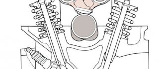
The valves (valve stem diameter 7 mm) in the cylinder head are arranged in two rows, V-shaped. The valves are steel, the outlet valves have a head made of heat-resistant steel and a welded bevel. The diameter of the intake valve disc is larger than that of the exhaust valve. The valve seats and guides are pressed into the cylinder head. Oil deflector caps made of oil-resistant rubber are placed on top of the valve guides. The valve closes under the action of a single spring. Its lower end rests on the washer, and its upper end rests on a plate held by two crackers. The folded crackers have the shape of a truncated cone on the outside, and on the inner surface there are three thrust flanges that fit into the grooves on the valve stem.
Valve mechanism : 1 — cracker; 2 - plate; 3 - spring; 4 — washer; 5 — exhaust valve; 6 - inlet valve
The valves are actuated by the camshaft cams through hydraulic tappets. The cam axis is shifted relative to the hydraulic pusher axis by 1 mm. Due to this, when the engine is running, the hydraulic pusher housing rotates around its axis, which contributes to its more uniform wear. For hydraulic tappets to operate, a constant supply of oil under pressure is required. To do this, a channel with a check ball valve is made in the cylinder head (it prevents oil from draining from the channels after stopping the engine), as well as channels on the lower plane of the camshaft bearing housing (they also supply oil to the camshaft journals). Hydraulic pushers are very sensitive to the quality of the oil and its purity. If there are mechanical impurities in the oil, rapid failure of the plunger pair of the hydraulic tappet is possible, which is accompanied by increased noise in the gas distribution mechanism and intense wear of the camshaft cams. A faulty hydraulic pusher cannot be repaired and must be replaced.
Oil pump: 1 - housing; 2 - cover; 3 - plug; 4 - sealing washer; 5 - spring; 6 - pressure reducing valve; 7 - drive gear; 8 - driven gear.
Engine lubrication is combined. Under pressure, oil is supplied to the main and connecting rod bearings of the crankshaft, the support-camshaft journal pairs, and hydraulic tappets. By spraying, oil is supplied to the cylinder walls (hereinafter referred to as the piston rings and pins), to the piston heads, to the camshaft cam-pushrod pairs and valve stems. The oil pump - with internal gears and pressure reducing valve - is attached to the cylinder block. The pump drive gear is mounted on two flats on the front end of the crankshaft. The maximum diameter of the socket for the driven (large) gear when worn should not exceed 75.10 mm, the minimum width of the segment on the body separating the drive and driven gears is 3.40 mm. The axial clearance for the drive gear should not exceed 0.12 mm, for the driven gear - 0.15 mm. The oil filter is full-flow, non-removable, equipped with bypass and anti-drainage valves. The crankcase ventilation system is closed, forced. Under the influence of vacuum in the intake manifold of a running engine, gases from the crankcase enter the cylinder head cover through a hose. Having passed through the oil separator located in the cylinder head cover, crankcase gases are cleared of oil particles and then enter the engine intake tract through the hoses of two circuits: the main circuit and the idle circuit. Through the main circuit hose, crankcase gases are discharged at partial and full engine loads into the space in front of the throttle valve. Through the idle circuit hose, crankcase gases are diverted into the space behind the throttle valve, both in partial and full load modes, and in idle mode. Engine management, power supply, cooling and exhaust systems are described in the relevant chapters.
Engine cooling system VAZ-21126 Priora
The engine cooling system consists of a cooling jacket, a radiator with an electric fan, a centrifugal water pump, a thermostat, an expansion tank and pipelines. The power supply system includes an electric fuel pump installed in the fuel tank, a throttle assembly, a fine fuel filter element, a fuel pressure corrector, injectors, and fuel pipelines. Differences in parts of the engine power supply system mod. 21126 Priora from engine mod. 2112: — the fuel rail is made in the form of a tube and there is no backflow of fuel, the ramp is made of stainless steel; — fuel injectors of reduced size are not interchangeable with mod. 2112 - a fuel pressure corrector of a modernized design is located in the fuel pump module, and not on the fuel rail; — in the throttle assembly there is no hole connecting the air supply hose to the intake module, bypassing the throttle valve. The appearance of the throttle assembly flange has been changed. The power system has a built-in fuel vapor recovery system with a carbon adsorber (see “Replacing components of the fuel vapor recovery system”), which prevents fuel vapors from leaking out.
Why does the engine stall?
Frequently encountered breakdowns of this power unit include such defects as unstable operation and engine tripping. Such failures occur due to malfunctions in engine components and parts:
- decrease in fuel pressure;
- defects in gas distribution mechanism elements;
- sensor malfunctions;
- violation of tightness in hoses;
- faulty throttle valve.
The power of the power unit is reduced for the following reasons:
- low compression in one or more cylinders;
- burnout of gaskets;
- wear of cylinder walls;
- erasing piston rings;
- deformation of pistons under the influence of high temperatures.
Engine friction can be eliminated by flushing the injectors. The reasons for unstable operation of the power unit may lie in the malfunction of the following devices:
- spark plugs for Priora 16 valves;
- ignition coil;
- throttle valve;
- idle air control;
- battery;
- starter;
- ignition coil;
- gasoline pump;
- fuel filter;
- fuel pressure regulating device.
You can replace the spark plugs on Priora yourself. To do this, you need to familiarize yourself with the principles of correct selection and replacement of these nodes, described in special articles on the Internet.
Technical parameters of the Lada Priora 21126 engine
The Priora power unit has overhead camshafts and a timing belt drive. The VAZ 21126 injection engine in question has 16 valves with in-line cylinders and Euro 3 emissions standards. Its main characteristics are shown in the table:
Technical parameters of engine 21126:
Video “Detailed instructions for replacing the seal”
Visual instructions on how to replace a unit at home are given in the video below (author - channel In Sandro's Garage).
If on old domestic cars the ignition switch could be changed without much difficulty, then on Priora and other front-wheel drive cars you can take longer with this repair. Basically, the reasons why replacement is necessary are as follows:
- failure of the contact group and unwillingness to repair it
- breakage of the key in the lock cylinder and the impossibility of removing it
- other breakdowns for which repairs cannot be carried out
To replace the ignition switch, you will need the following tool:
- Sharp and thin chisel
- Hammer
- 10 mm wrench
- Phillips screwdriver
- Long nose pliers
Main malfunctions of the VAZ 2170 engine (16 valves)
Experienced car owners have the skills to identify engine breakdowns based on the quality of Priora exhaust gases:
- Bluish smoke indicates the presence of lubricants inside the combustion chamber. Regular blue smoke also indicates significant wear of the connecting rod and piston group and cylinders. Wear of the oil seals of 16 engine valves provokes increased smoke during prolonged idling or sudden braking;
- Black smoke occurs when an excessively rich mixture is formed, which indicates a breakdown of the engine control system or injectors;
- Grayish and white saturated smoke indicates the presence of moisture in the exhaust gases, which is a consequence of a defective head gasket, and, consequently, coolant leaking into the combustion chamber. This factor is normal during cold and wet weather.
Among the main problem areas of the Lada Priora engine, it is worth noting the following:
- Failure of the pump (liquid pump), which can cause engine overheating;
- Liquid leakage at the connection points of the radiator tubes;
- Mixing of the timing belt tension roller, which is accompanied by a gradually increasing hum when driving;
- Oil leakage under the valve cover.